Page 1457 of 2890
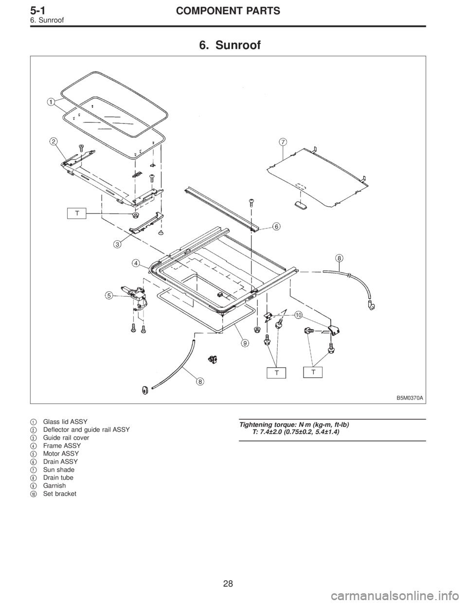
6. Sunroof
B5M0370A
�1Glass lid ASSY
�
2Deflector and guide rail ASSY
�
3Guide rail cover
�
4Frame ASSY
�
5Motor ASSY
�
6Drain ASSY
�
7Sun shade
�
8Drain tube
�
9Garnish
�
10Set bracket
Tightening torque: N⋅m (kg-m, ft-lb)
T: 7.4±2.0 (0.75±0.2, 5.4±1.4)
28
5-1COMPONENT PARTS
6. Sunroof
Page 1460 of 2890
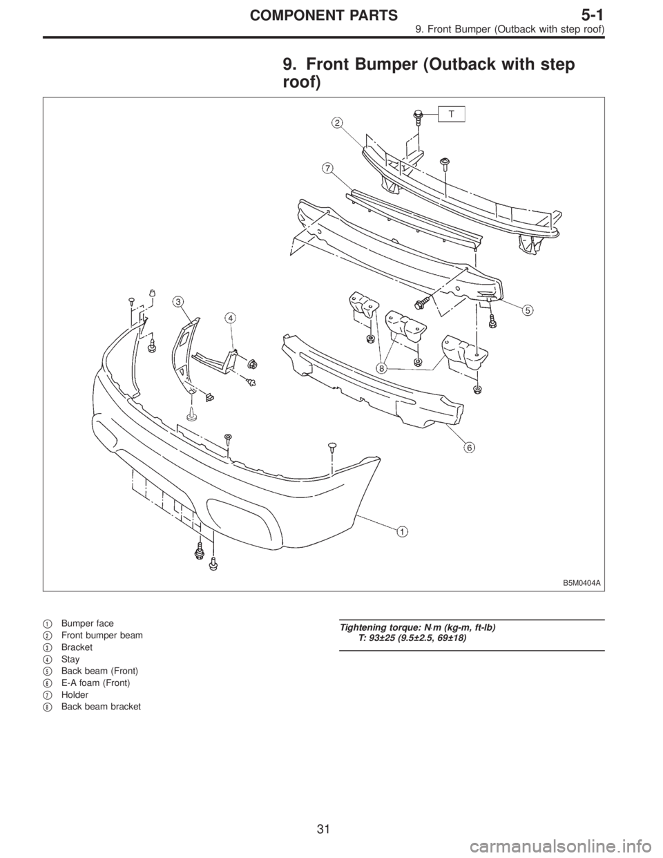
9. Front Bumper (Outback with step
roof)
B5M0404A
�1Bumper face
�
2Front bumper beam
�
3Bracket
�
4Stay
�
5Back beam (Front)
�
6E-A foam (Front)
�
7Holder
�
8Back beam bracket
Tightening torque: N⋅m (kg-m, ft-lb)
T: 93±25 (9.5±2.5, 69±18)
31
5-1COMPONENT PARTS
9. Front Bumper (Outback with step roof)
Page 1461 of 2890
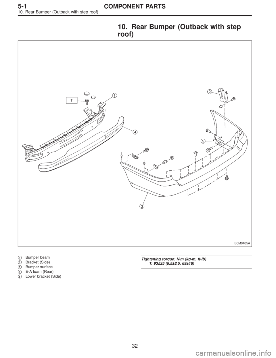
10. Rear Bumper (Outback with step
roof)
B5M0405A
�1Bumper beam
�
2Bracket (Side)
�
3Bumper surface
�
4E-A foam (Rear)
�
5Lower bracket (Side)
Tightening torque: N⋅m (kg-m, ft-lb)
T: 93±25 (9.5±2.5, 69±18)
32
5-1COMPONENT PARTS
10. Rear Bumper (Outback with step roof)
Page 1467 of 2890
4. Front Bumper
A: REMOVAL
SUPPLEMENTAL RESTRAINT SYSTEM“AIRBAG”
Airbag system wiring harness is routed near the front
bumper assembly.
CAUTION:
�All Airbag system wiring harness and connectors
are colored yellow. Do not use electrical test equip-
ment on these circuits.
�Be careful not to damage Airbag system wiring har-
ness when servicing the front bumper assembly.
B5M0273
1. EXCEPT OUTBACK WITH STEP ROOF
1) Disconnect the ground cable from the battery.
2) Remove two bolts from lower center of bumper.
3) Remove mud guard.
NOTE:
It is not necessary to remove the entire mud guard.
Remove clips from the front section of mud guard, if nec-
essary.
4) Remove the canister.
B5M0274
5) Remove two bolts from side of bumper.
6) Remove front grill.
7) Remove headlight.
B5M0376
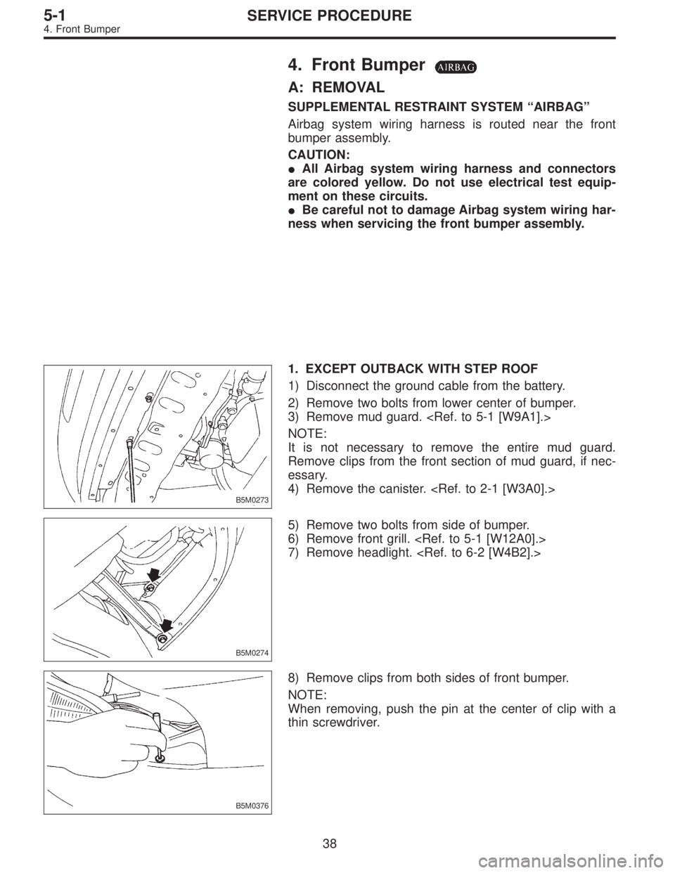
8) Remove clips from both sides of front bumper.
NOTE:
When removing, push the pin at the center of clip with a
thin screwdriver.
38
5-1SERVICE PROCEDURE
4. Front Bumper
Page 1468 of 2890
B5M0275
9) Remove bolts (engine compartment side) from bumper
stays.
B5M0276
10) Remove front bumper assembly.
NOTE:
Front bumper surface is accessible for removal after
removing the following parts:
Two bolts (on the lower center of bumper), mud guard,
bolts (on the side of bumper), front grille, headlight, clips
(on both sides of front bumper), clips (on the upper section
of bumper), and clips (on the lower section of bumper).
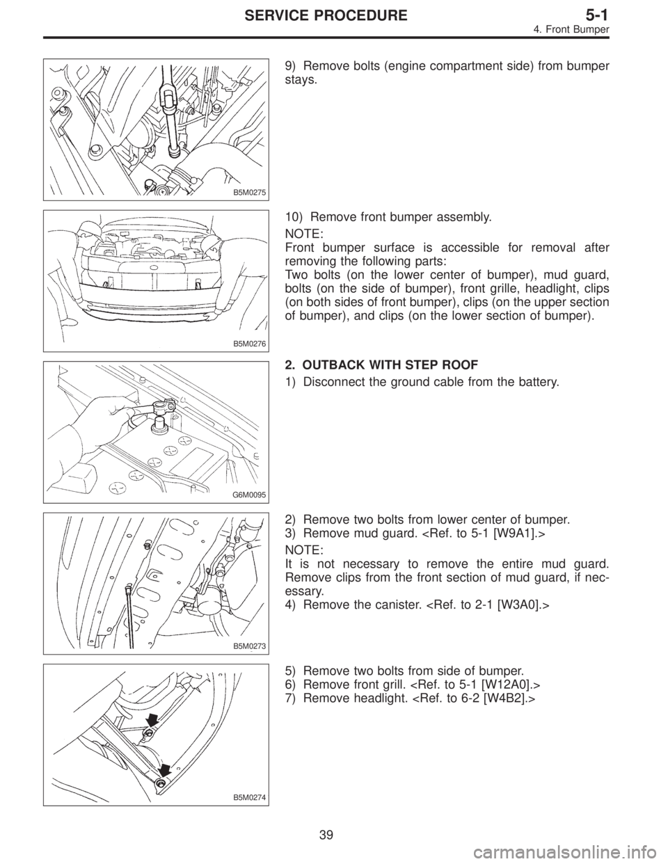
G6M0095
2. OUTBACK WITH STEP ROOF
1) Disconnect the ground cable from the battery.
B5M0273
2) Remove two bolts from lower center of bumper.
3) Remove mud guard.
NOTE:
It is not necessary to remove the entire mud guard.
Remove clips from the front section of mud guard, if nec-
essary.
4) Remove the canister.
B5M0274
5) Remove two bolts from side of bumper.
6) Remove front grill.
7) Remove headlight.
39
5-1SERVICE PROCEDURE
4. Front Bumper
Page 1469 of 2890
B5M0376
8) Remove fog lamps.
9) Remove clips from both sides of front bumper.
NOTE:
When removing, push the pin at the center of clip with a
thin screwdriver.
B5M0275
10) Remove bolts (engine compartment side) from
bumper stays.
B5M0406
11) Remove front bumper assembly.
NOTE:
Front bumper surface is accessible for removal after
removing the following parts:
Two bolts (on the lower center of bumper), mud guard,
bolts (on the side of bumper), front grille, headlight, clips
(on both sides of front bumper), clips (on the upper section
of bumper), and clips (on the lower section of bumper).
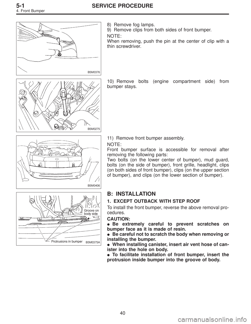
B5M0375A
B: INSTALLATION
1. EXCEPT OUTBACK WITH STEP ROOF
To install the front bumper, reverse the above removal pro-
cedures.
CAUTION:
�Be extremely careful to prevent scratches on
bumper face as it is made of resin.
�Be careful not to scratch the body when removing or
installing the bumper.
�When installing canister, insert air vent hose of can-
ister into the hole on body.
�To facilitate installation of front bumper, insert the
protrusion inside bumper into the groove of body.
40
5-1SERVICE PROCEDURE
4. Front Bumper
Page 1470 of 2890
2. OUTBACK WITH STEP ROOF
To install the front bumper, reverse the above removal pro-
cedures.
CAUTION:
�Be extremely careful to prevent scratches on
bumper face as it is made of resin.
�Be careful not to scratch the body when removing or
installing the bumper.
�When installing canister, insert air vent hose of can-
ister into the hole on body.
41
5-1SERVICE PROCEDURE
4. Front Bumper
Page 1472 of 2890
B5M0281
4) Remove bolts from bumper stays.
B5M0282
5) Remove rear bumper assembly.
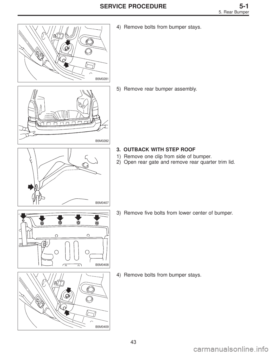
B5M0407
3. OUTBACK WITH STEP ROOF
1) Remove one clip from side of bumper.
2) Open rear gate and remove rear quarter trim lid.
B5M0408
3) Remove five bolts from lower center of bumper.
B5M0409
4) Remove bolts from bumper stays.
43
5-1SERVICE PROCEDURE
5. Rear Bumper