Page 321 of 2890
G2M0198
4) Manually push valve rocker (at lash adjuster location) to
check that there is no air in it.
NOTE:
When air is in lash adjuster, valve rocker moves when
pushed with fingers.
G2M0199
5) If air is in lash adjuster, remove valve rocker assembly
from engine and bleed air completely.
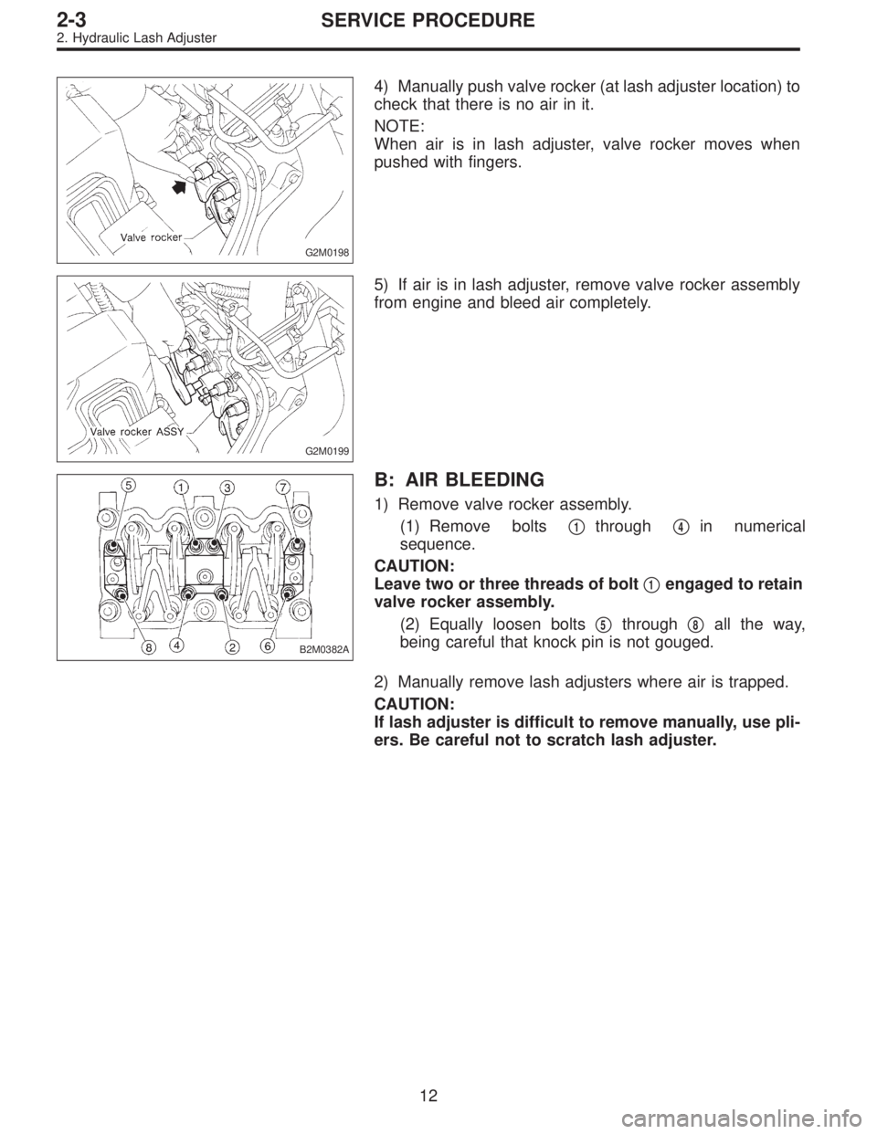
B2M0382A
B: AIR BLEEDING
1) Remove valve rocker assembly.
(1) Remove bolts�
1through�4in numerical
sequence.
CAUTION:
Leave two or three threads of bolt�
1engaged to retain
valve rocker assembly.
(2) Equally loosen bolts�
5through�8all the way,
being careful that knock pin is not gouged.
2) Manually remove lash adjusters where air is trapped.
CAUTION:
If lash adjuster is difficult to remove manually, use pli-
ers. Be careful not to scratch lash adjuster.
12
2-3SERVICE PROCEDURE
2. Hydraulic Lash Adjuster
Page 322 of 2890
G2M0131
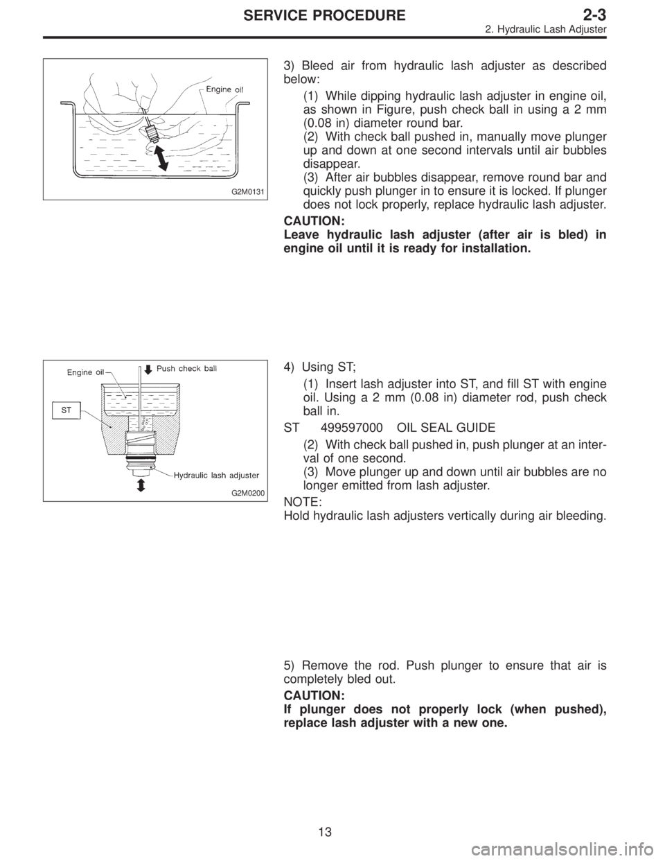
3) Bleed air from hydraulic lash adjuster as described
below:
(1) While dipping hydraulic lash adjuster in engine oil,
as shown in Figure, push check ball in usinga2mm
(0.08 in) diameter round bar.
(2) With check ball pushed in, manually move plunger
up and down at one second intervals until air bubbles
disappear.
(3) After air bubbles disappear, remove round bar and
quickly push plunger in to ensure it is locked. If plunger
does not lock properly, replace hydraulic lash adjuster.
CAUTION:
Leave hydraulic lash adjuster (after air is bled) in
engine oil until it is ready for installation.
G2M0200
4) Using ST;
(1) Insert lash adjuster into ST, and fill ST with engine
oil. Usinga2mm(0.08 in) diameter rod, push check
ball in.
ST 499597000 OIL SEAL GUIDE
(2) With check ball pushed in, push plunger at an inter-
val of one second.
(3) Move plunger up and down until air bubbles are no
longer emitted from lash adjuster.
NOTE:
Hold hydraulic lash adjusters vertically during air bleeding.
5) Remove the rod. Push plunger to ensure that air is
completely bled out.
CAUTION:
If plunger does not properly lock (when pushed),
replace lash adjuster with a new one.
13
2-3SERVICE PROCEDURE
2. Hydraulic Lash Adjuster
Page 323 of 2890
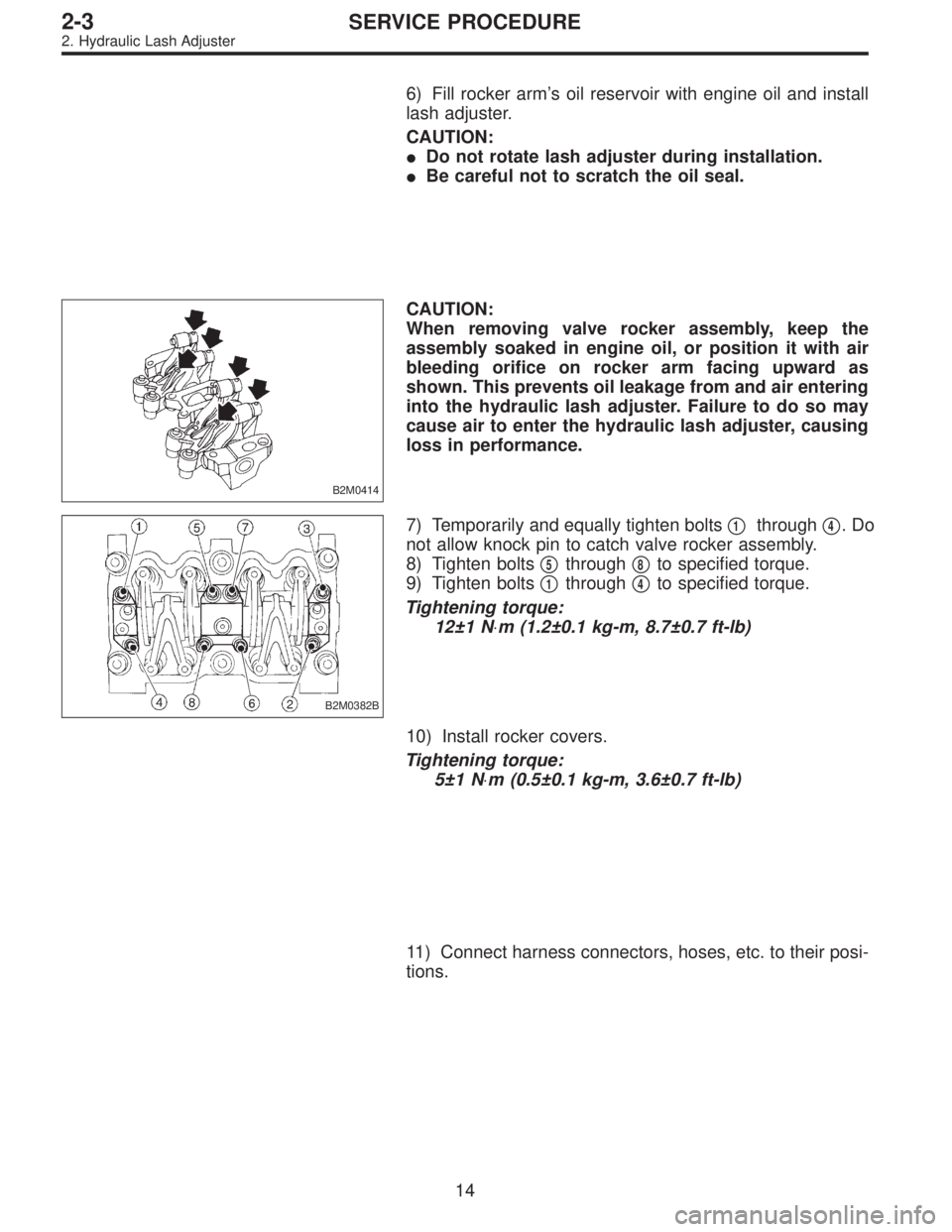
6) Fill rocker arm’s oil reservoir with engine oil and install
lash adjuster.
CAUTION:
�Do not rotate lash adjuster during installation.
�Be careful not to scratch the oil seal.
B2M0414
CAUTION:
When removing valve rocker assembly, keep the
assembly soaked in engine oil, or position it with air
bleeding orifice on rocker arm facing upward as
shown. This prevents oil leakage from and air entering
into the hydraulic lash adjuster. Failure to do so may
cause air to enter the hydraulic lash adjuster, causing
loss in performance.
B2M0382B
7) Temporarily and equally tighten bolts�1through�4.Do
not allow knock pin to catch valve rocker assembly.
8) Tighten bolts�
5through�8to specified torque.
9) Tighten bolts�
1through�4to specified torque.
Tightening torque:
12±1 N⋅m (1.2±0.1 kg-m, 8.7±0.7 ft-lb)
10) Install rocker covers.
Tightening torque:
5±1 N⋅m (0.5±0.1 kg-m, 3.6±0.7 ft-lb)
11) Connect harness connectors, hoses, etc. to their posi-
tions.
14
2-3SERVICE PROCEDURE
2. Hydraulic Lash Adjuster
Page 337 of 2890
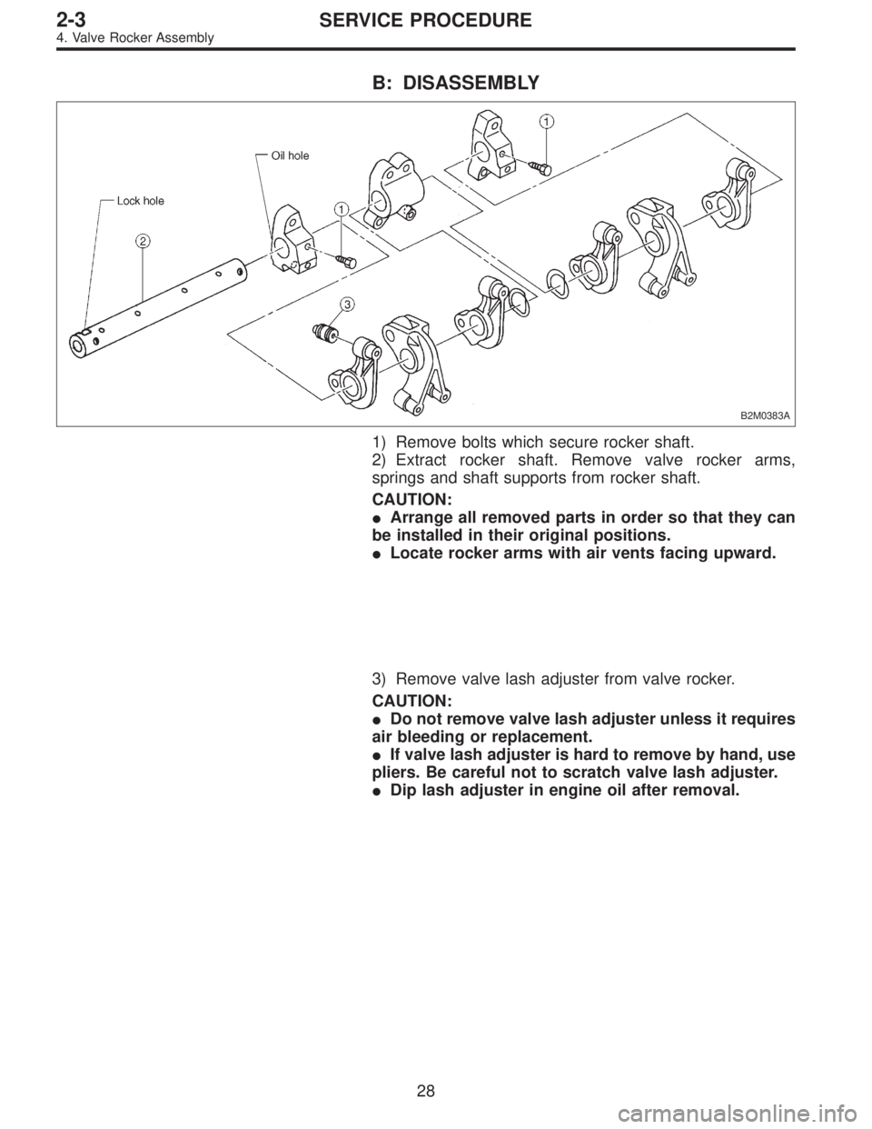
B: DISASSEMBLY
B2M0383A
1) Remove bolts which secure rocker shaft.
2) Extract rocker shaft. Remove valve rocker arms,
springs and shaft supports from rocker shaft.
CAUTION:
�Arrange all removed parts in order so that they can
be installed in their original positions.
�Locate rocker arms with air vents facing upward.
3) Remove valve lash adjuster from valve rocker.
CAUTION:
�Do not remove valve lash adjuster unless it requires
air bleeding or replacement.
�If valve lash adjuster is hard to remove by hand, use
pliers. Be careful not to scratch valve lash adjuster.
�Dip lash adjuster in engine oil after removal.
28
2-3SERVICE PROCEDURE
4. Valve Rocker Assembly
Page 338 of 2890
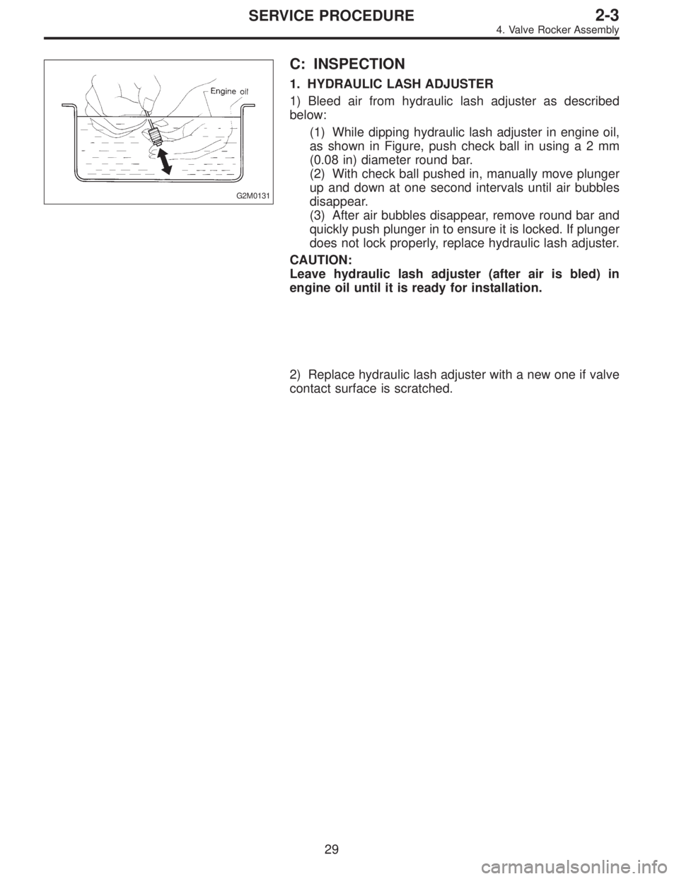
G2M0131
C: INSPECTION
1. HYDRAULIC LASH ADJUSTER
1) Bleed air from hydraulic lash adjuster as described
below:
(1) While dipping hydraulic lash adjuster in engine oil,
as shown in Figure, push check ball in usinga2mm
(0.08 in) diameter round bar.
(2) With check ball pushed in, manually move plunger
up and down at one second intervals until air bubbles
disappear.
(3) After air bubbles disappear, remove round bar and
quickly push plunger in to ensure it is locked. If plunger
does not lock properly, replace hydraulic lash adjuster.
CAUTION:
Leave hydraulic lash adjuster (after air is bled) in
engine oil until it is ready for installation.
2) Replace hydraulic lash adjuster with a new one if valve
contact surface is scratched.
29
2-3SERVICE PROCEDURE
4. Valve Rocker Assembly
Page 340 of 2890
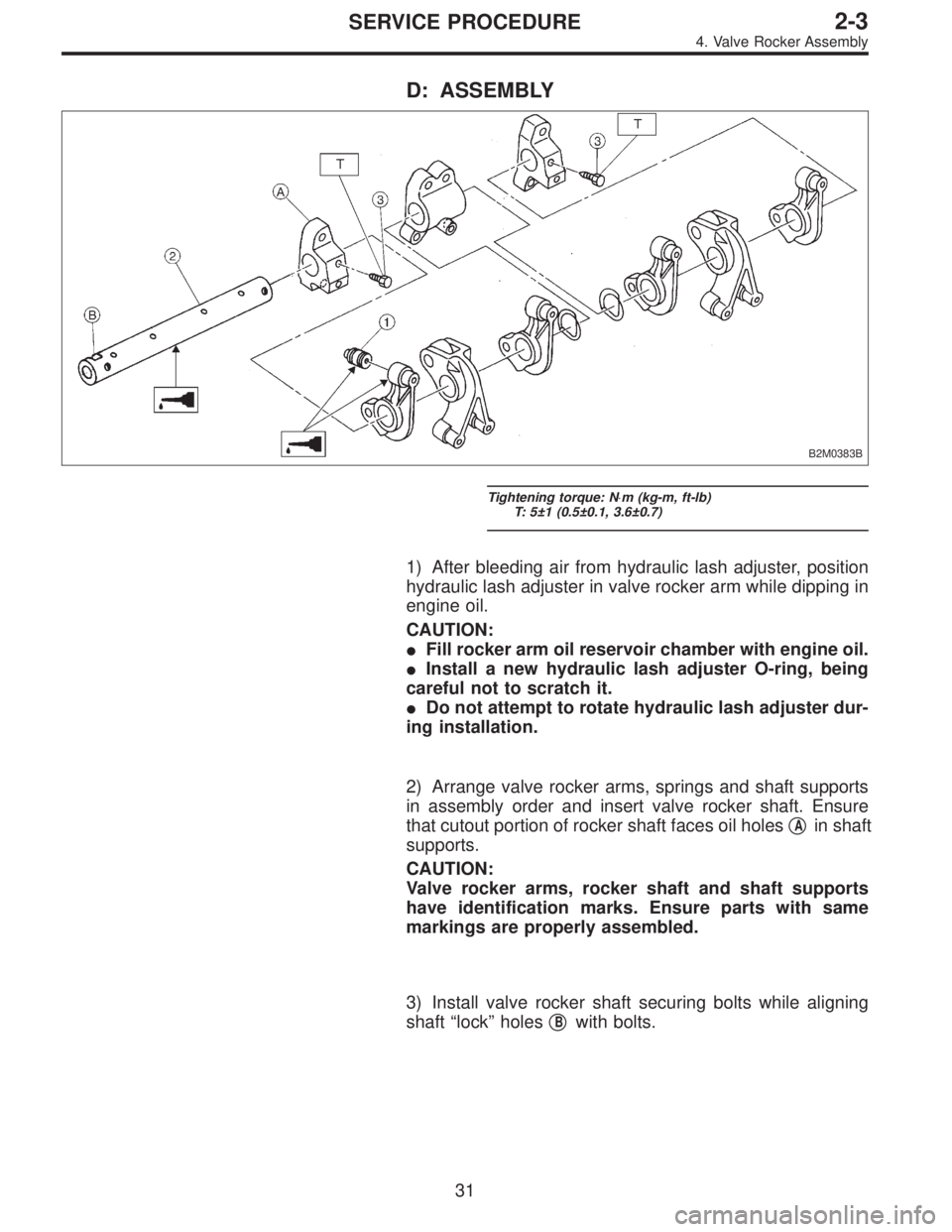
D: ASSEMBLY
B2M0383B
Tightening torque: N⋅m (kg-m, ft-lb)
T: 5±1 (0.5±0.1, 3.6±0.7)
1) After bleeding air from hydraulic lash adjuster, position
hydraulic lash adjuster in valve rocker arm while dipping in
engine oil.
CAUTION:
�Fill rocker arm oil reservoir chamber with engine oil.
�Install a new hydraulic lash adjuster O-ring, being
careful not to scratch it.
�Do not attempt to rotate hydraulic lash adjuster dur-
ing installation.
2) Arrange valve rocker arms, springs and shaft supports
in assembly order and insert valve rocker shaft. Ensure
that cutout portion of rocker shaft faces oil holes�
Ain shaft
supports.
CAUTION:
Valve rocker arms, rocker shaft and shaft supports
have identification marks. Ensure parts with same
markings are properly assembled.
3) Install valve rocker shaft securing bolts while aligning
shaft“lock”holes�
Bwith bolts.
31
2-3SERVICE PROCEDURE
4. Valve Rocker Assembly
Page 466 of 2890
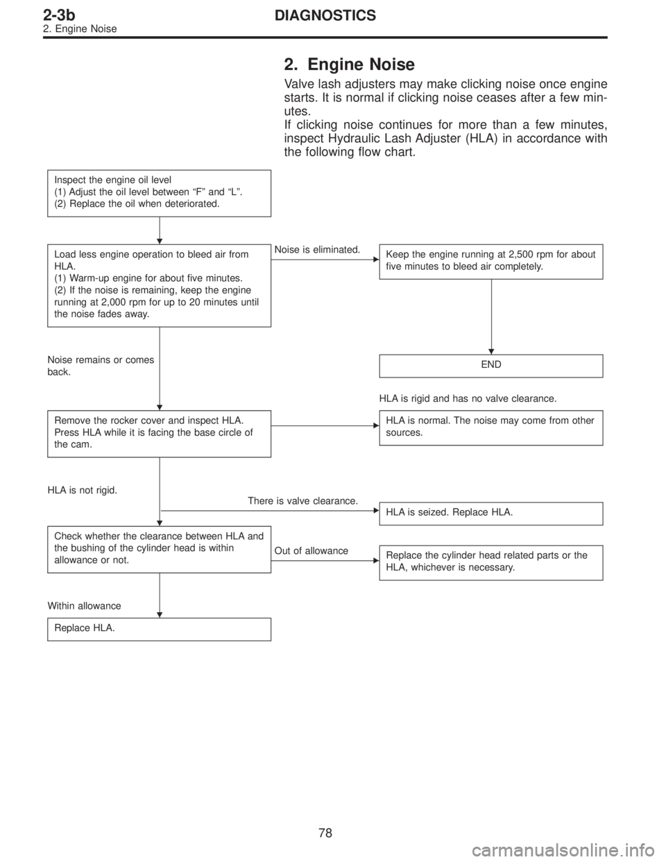
2. Engine Noise
Valve lash adjusters may make clicking noise once engine
starts. It is normal if clicking noise ceases after a few min-
utes.
If clicking noise continues for more than a few minutes,
inspect Hydraulic Lash Adjuster (HLA) in accordance with
the following flow chart.
Inspect the engine oil level
(1) Adjust the oil level between“F”and“L”.
(2) Replace the oil when deteriorated.
Load less engine operation to bleed air from
HLA.
(1) Warm-up engine for about five minutes.
(2) If the noise is remaining, keep the engine
running at 2,000 rpm for up to 20 minutes until
the noise fades away.�Noise is eliminated.
Keep the engine running at 2,500 rpm for about
five minutes to bleed air completely.
Noise remains or comes
back.END
HLA is rigid and has no valve clearance.
Remove the rocker cover and inspect HLA.
Press HLA while it is facing the base circle of
the cam.
�HLA is normal. The noise may come from other
sources.
HLA is not rigid.
There is valve clearance.
Check whether the clearance between HLA and
the bushing of the cylinder head is within
allowance or not.
HLA is seized. Replace HLA.
�Out of allowance
Replace the cylinder head related parts or the
HLA, whichever is necessary.
Within allowance
Replace HLA.
�
�
�
�
�
�
78
2-3bDIAGNOSTICS
2. Engine Noise
Page 733 of 2890
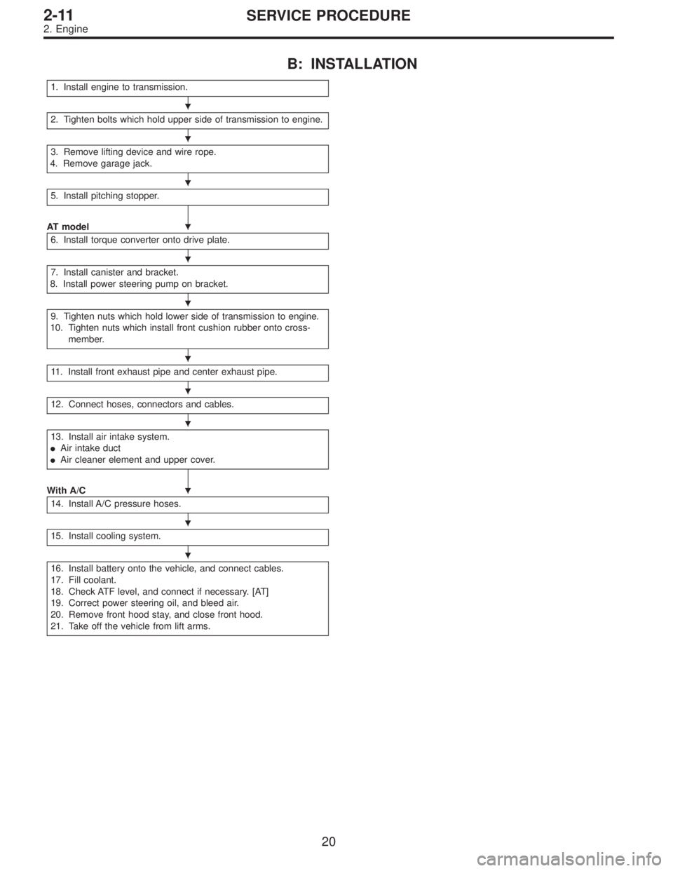
B: INSTALLATION
1. Install engine to transmission.
2. Tighten bolts which hold upper side of transmission to engine.
3. Remove lifting device and wire rope.
4. Remove garage jack.
5. Install pitching stopper.
AT model
6. Install torque converter onto drive plate.
7. Install canister and bracket.
8. Install power steering pump on bracket.
9. Tighten nuts which hold lower side of transmission to engine.
10. Tighten nuts which install front cushion rubber onto cross-
member.
11. Install front exhaust pipe and center exhaust pipe.
12. Connect hoses, connectors and cables.
13. Install air intake system.
�Air intake duct
�Air cleaner element and upper cover.
With A/C
14. Install A/C pressure hoses.
15. Install cooling system.
16. Install battery onto the vehicle, and connect cables.
17. Fill coolant.
18. Check ATF level, and connect if necessary. [AT]
19. Correct power steering oil, and bleed air.
20. Remove front hood stay, and close front hood.
21. Take off the vehicle from lift arms.
�
�
�
�
�
�
�
�
�
�
�
�
20
2-11SERVICE PROCEDURE
2. Engine