Page 2343 of 2890
B: ELECTRICAL INSPECTION
1. WARNING LIGHT ILLUMINATION PATTERN
B4M0781A
1) When the ABS warning light does not illuminate in
accordance with this illumination pattern, there must be an
electrical malfunction.
2) When the ABS warning light remains constantly OFF,
refer to“7. Diagnostics Chart for ABS Warning Light Circuit
and Diagnosis Circuit Failure”in this section, for repair.
3
4-4cBRAKES [ABS 5.3 TYPE]
2. Pre-inspection
Page 2344 of 2890
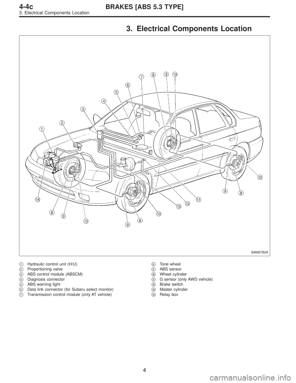
3. Electrical Components Location
B4M0782A
�1Hydraulic control unit (H/U)
�
2Proportioning valve
�
3ABS control module (ABSCM)
�
4Diagnosis connector
�
5ABS warning light
�
6Data link connector (for Subaru select monitor)
�
7Transmission control module (only AT vehicle)�
8Tone wheel
�
9ABS sensor
�
10Wheel cylinder
�
11G sensor (only AWD vehicle)
�
12Brake switch
�
13Master cylinder
�
14Relay box
4
4-4cBRAKES [ABS 5.3 TYPE]
3. Electrical Components Location
Page 2345 of 2890
B4M0783AB4M0784A
B4M0230B
B4M0786A
B4M0646BB4M0231B
B4M0645B
5
4-4cBRAKES [ABS 5.3 TYPE]
3. Electrical Components Location
Page 2346 of 2890
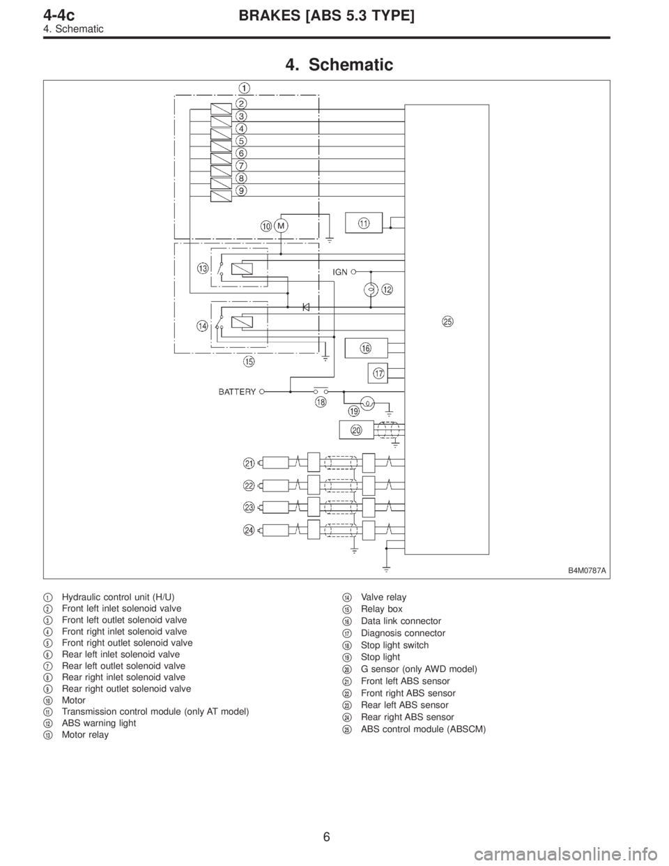
4. Schematic
B4M0787A
�1Hydraulic control unit (H/U)
�
2Front left inlet solenoid valve
�
3Front left outlet solenoid valve
�
4Front right inlet solenoid valve
�
5Front right outlet solenoid valve
�
6Rear left inlet solenoid valve
�
7Rear left outlet solenoid valve
�
8Rear right inlet solenoid valve
�
9Rear right outlet solenoid valve
�
10Motor
�
11Transmission control module (only AT model)
�
12ABS warning light
�
13Motor relay�
14Valve relay
�
15Relay box
�
16Data link connector
�
17Diagnosis connector
�
18Stop light switch
�
19Stop light
�
20G sensor (only AWD model)
�
21Front left ABS sensor
�
22Front right ABS sensor
�
23Rear left ABS sensor
�
24Rear right ABS sensor
�
25ABS control module (ABSCM)
6
4-4cBRAKES [ABS 5.3 TYPE]
4. Schematic
Page 2347 of 2890
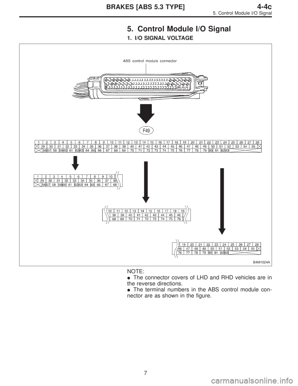
5. Control Module I/O Signal
1. I/O SIGNAL VOLTAGE
B4M1024A
NOTE:
�The connector covers of LHD and RHD vehicles are in
the reverse directions.
�The terminal numbers in the ABS control module con-
nector are as shown in the figure.
7
4-4cBRAKES [ABS 5.3 TYPE]
5. Control Module I/O Signal
Page 2348 of 2890
Front left wheel 49—19
0.12—1V
(When it is 20 Hz.) Front right wheel 14—15
Rear le")
Contents Terminal No.Input/Output signal
Measured value and measuring conditions
ABS sensor
(Wheel
speed
sensor)Front left wheel 49—19
0.12—1V
(When it is 20 Hz.) Front right wheel 14—15
Rear left wheel 16—17
Rear right wheel 18—46
Hydraulic
control unitSolenoid
valveFront left outlet 51—1
10—13 V when the valve is OFF and
less than 1.5 V when the valve is ON. Front right outlet 3—1
Rear left outlet 4—1
Rear right outlet 50—1
Front left inlet 24—1
Front right inlet 30—1
Rear left inlet 31—1
Rear right inlet 23—1
Relay boxValve relay power supply 27—110—13 V when ignition switch is ON.
Valve relay coil 47—1 Less than 1.5 V when ignition switch is ON.
Motor relay coil 22—1More than 10 V when the ABS control does not operate still
and less than 1.5 V when ABS operates.
Motor monitoring 10—1Less than 1.5 V when the ABS control does not operate still
and more than 10 V when ABS operates.
G sensor
(AWD
model only)power supply 8—45 4.75—5.25 V
ground 45—
output 7—45 2.3±0.2 V when vehicle is in horizontal position.
Stop light switch 36—1Less than 1.5 V when the stop light is OFF and more than
4.5 V when the stop light is ON.
ABS warning light 54—1Less than 1.5 V during 1.5 seconds when ignition switch is
ON, and 10—14 V after 1.5 seconds.
AT ABS signal
(AT model only)12—1Less than 1.5 V when the ABS control does not operate still
and more than 5.5 V when ABS operates.
ABS operation signal monitor 39—1Less than 1.5 V when the ABS control does not operate still
and more than 5.5 V when ABS operates.
Select
monitorData is received. 11—1 Less than 1.5 V when no data is received.
Data is sent. 38—1 4.75—5.25 V when no data is sent.
Diagnosis
connectorTerminal No. 3 5—110—14 V when ignition switch is ON.
Terminal No. 6 13—110—14 V when ignition switch is ON.
Power supply 28—110—14 V when ignition switch is ON.
Grounding line 1—
Grounding line 55—
8
4-4cBRAKES [ABS 5.3 TYPE]
5. Control Module I/O Signal
Page 2349 of 2890
2. I/O SIGNAL DIAGRAM
B4M0788A
9
4-4cBRAKES [ABS 5.3 TYPE]
5. Control Module I/O Signal
Page 2350 of 2890
![SUBARU LEGACY 1996 Service Repair Manual 6. Diagnostics Chart for On-board
Diagnosis System
A: BASIC DIAGNOSTICS PROCEDURE
TROUBLE OCCURS.
Is Select Monitor available?
No
�Ye s
10. Diagnostic Chart with Select
Monitor <Ref. to 4-4c [T10A0].>](/manual-img/17/57433/w960_57433-2349.png "SUBARU LEGACY 1996 Service Repair Manual 6. Diagnostics Chart for On-board
Diagnosis System
A: BASIC DIAGNOSTICS PROCEDURE
TROUBLE OCCURS.
Is Select Monitor available?
No
�Ye s
10. Diagnostic Chart with Select
Monitor <Ref. to 4-4c [T10A0].>")
6. Diagnostics Chart for On-board
Diagnosis System
A: BASIC DIAGNOSTICS PROCEDURE
TROUBLE OCCURS.
Is Select Monitor available?
No
�Ye s
10. Diagnostic Chart with Select
Monitor
Ask the customer when and how the
trouble occurred using interview
check list.
PRE-INSPECTION
CALLING UP A TROUBLE CODE.
�No trouble code is readable.
�
Inspection using Diagnostic Chart for
Warning Light Failure.
Record all trouble codes.
Trouble codes
are issued.
�Only the start code is issued.
Inspection using General Diagnostics
Chart
Perform diagnostics in accordance with trouble code.
Trouble code
designated.
�
Repair.�
Clear memory.
INSPECTION MODE
CALLING UP A TROUBLE CODE.
Only the start code is issued.
CONFIRMATION TEST
END
NOTE:
�To check harness for broken wires or short circuits,
shake it while holding it or the connector.
�When ABS warning light illuminates, read and record
trouble code indicated by ABS warning light.
�
�
�
�
�
�
�
�
�
�
�
�
10
4-4cBRAKES [ABS 5.3 TYPE]
6. Diagnostics Chart for On-board Diagnosis System
 When the ABS warning light does not illuminate in
accordance with this illumination pattern, there must be an
electrical malf")
![SUBARU LEGACY 1996 Service Repair Manual B4M0783AB4M0784A
B4M0230B
B4M0786A
B4M0646BB4M0231B
B4M0645B
5
4-4cBRAKES [ABS 5.3 TYPE]
3. Electrical Components Location](/manual-img/17/57433/w960_57433-2344.png "SUBARU LEGACY 1996 Service Repair Manual B4M0783AB4M0784A
B4M0230B
B4M0786A
B4M0646BB4M0231B
B4M0645B
5
4-4cBRAKES [ABS 5.3 TYPE]
3. Electrical Components Location")
![SUBARU LEGACY 1996 Service Repair Manual 2. I/O SIGNAL DIAGRAM
B4M0788A
9
4-4cBRAKES [ABS 5.3 TYPE]
5. Control Module I/O Signal](/manual-img/17/57433/w960_57433-2348.png "SUBARU LEGACY 1996 Service Repair Manual 2. I/O SIGNAL DIAGRAM
B4M0788A
9
4-4cBRAKES [ABS 5.3 TYPE]
5. Control Module I/O Signal")