Page 2367 of 2890

8. Diagnostics Chart with Trouble Code
A: LIST OF TROUBLE CODE
Trouble code Contents of diagnosis Ref. to
11Start code
�Trouble code is shown after start code.
�Only start code is shown in normal condition.—
21
Abnormal ABS sensor
(Open circuit or input voltage too high)Front right ABS sensor
4-4c [T8B0] 23 Front left ABS sensor
25 Rear right ABS sensor
27 Rear left ABS sensor
22
Abnormal ABS sensor
(Abnormal ABS sensor signal)Front right ABS sensor
4-4c [T8C0] 24 Front left ABS sensor
26 Rear right ABS sensor
28 Rear left ABS sensor
29 Any one of four 4-4c [T8D0]
31
Abnormal solenoid valve circuit(s) in
hydraulic unitFront right inlet valve 4-4c [T8E0]
32 Front right outlet valve 4-4c [T8F0]
33 Front left inlet valve 4-4c [T8E0]
34 Front left outlet valve 4-4c [T8F0]
35 Rear right inlet valve 4-4c [T8E0]
36 Rear right outlet valve 4-4c [T8F0]
37 Rear left inlet valve 4-4c [T8E0]
38 Rear left outlet valve 4-4c [T8F0]
41 Abnormal ABS control module 4-4c [T8G0]
42 Source voltage is low. 4-4c [T8H0]
44 A combination of AT control abnormals 4-4c [T8I0]
46 Abnormal G sensor power supply voltage 4-4c [T8J0]
51 Abnormal valve relay4-4c [T8K0]
52 Abnormal motor and/or motor relay 4-4c [T8L0]
54 Abnormal stop light switch 4-4c [T8M0]
56 Abnormal G sensor output voltage 4-4c [T8N0]
27
4-4cBRAKES [ABS 5.3 TYPE]
8. Diagnostics Chart with Trouble Code
Page 2368 of 2890
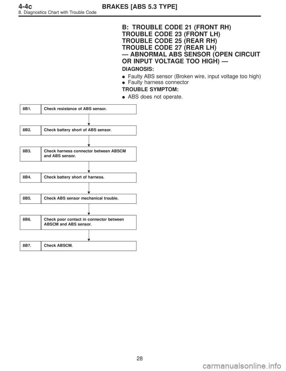
B: TROUBLE CODE 21 (FRONT RH)
TROUBLE CODE 23 (FRONT LH)
TROUBLE CODE 25 (REAR RH)
TROUBLE CODE 27 (REAR LH)
—ABNORMAL ABS SENSOR (OPEN CIRCUIT
OR INPUT VOLTAGE TOO HIGH)—
DIAGNOSIS:
�Faulty ABS sensor (Broken wire, input voltage too high)
�Faulty harness connector
TROUBLE SYMPTOM:
�ABS does not operate.
8B1.Check resistance of ABS sensor.
8B2.Check battery short of ABS sensor.
8B3.Check harness connector between ABSCM
and ABS sensor.
8B4.Check battery short of harness.
8B5.Check ABS sensor mechanical trouble.
8B6.Check poor contact in connector between
ABSCM and ABS sensor.
8B7.Check ABSCM.
�
�
�
�
�
�
28
4-4cBRAKES [ABS 5.3 TYPE]
8. Diagnostics Chart with Trouble Code
Page 2369 of 2890
WIRING DIAGRAM:
B4M1035
29
4-4cBRAKES [ABS 5.3 TYPE]
8. Diagnostics Chart with Trouble Code
Page 2370 of 2890
 Turn ignition switch to OFF.
2) Disconnect connector from ABS sensor.
3) Measure resistance of ABS sensor connector terminals.
: Trouble code/C")
B4M0806B
B4M1036A
8B1
CHECK RESISTANCE OF ABS SENSOR.
1) Turn ignition switch to OFF.
2) Disconnect connector from ABS sensor.
3) Measure resistance of ABS sensor connector terminals.
: Trouble code/Connector & terminal
21/to (B6) No. 1—No. 2
23/to (B15) No. 1—No. 2
25/to (P8) No. 1—No. 2
27/to (P9) No. 1—No. 2
Is resistance 0.8—1.2 kΩ?
: Go to step8B2.
: Replace ABS sensor.
B4M0807B
B4M1037A
8B2CHECK BATTERY SHORT OF ABS SEN-
SOR.
1) Disconnect connector from ABSCM.
2) Turn ignition switch to ON.
3) Measure voltage between ABS sensor and chassis
ground.
: Trouble code/Connector & terminal
21/to (B6) No. 1 (+)—Chassis ground (�)
23/to (B15) No. 1 (+)—Chassis ground (�)
25/to (P8) No. 1 (+)—Chassis ground (�)
27/to (P9) No. 1 (+)—Chassis ground (�)
Is voltage 0 V?
: Go to next step.
: Replace ABS sensor.
4) Turn ignition switch to OFF.
5) Measure voltage between ABS sensor and chassis
ground.
: Trouble code/Connector & terminal
21/to (B6) No. 1 (+)—Chassis ground (�)
23/to (B15) No. 1 (+)—Chassis ground (�)
25/to (P8) No. 1 (+)—Chassis ground (�)
27/to (P9) No. 1 (+)—Chassis ground (�)
Is voltage 0 V?
: Go to step8B3.
: Replace ABS sensor.
30
4-4cBRAKES [ABS 5.3 TYPE]
8. Diagnostics Chart with Trouble Code
Page 2371 of 2890
 Connect connector to ABS sensor.
2) Measure resistance between ABSCM connector termi-
nals.
: Trouble code/Connector & terminal
21/")
B4M0809A
8B3CHECK HARNESS CONNECTOR
BETWEEN ABSCM AND ABS SENSOR.
1) Connect connector to ABS sensor.
2) Measure resistance between ABSCM connector termi-
nals.
: Trouble code/Connector & terminal
21/(F49) No. 14—No. 15
23/(F49) No. 49—No. 19
25/(F49) No. 18—No. 46
27/(F49) No. 16—No. 17
Is resistance 0.8—1.2 kΩ?
: Go to step8B4.
: Repair harness connector between ABSCM and
ABS sensor.
B4M0810A
8B4
CHECK BATTERY SHORT OF HARNESS.
1) Turn ignition switch to ON.
2) Measure voltage between ABSCM connector and chas-
sis ground.
: Trouble code/Connector & terminal
21/(F49) No. 14 (+)—Chassis ground (�)
23/(F49) No. 49 (+)—Chassis ground (�)
25/(F49) No. 18 (+)—Chassis ground (�)
27/(F49) No. 16 (+)—Chassis ground (�)
Is voltage 0 V?
: Go to next step.
: Repair harness between ABSCM and ABS sen-
sor.
3) Turn ignition switch to OFF.
4) Measure voltage between ABSCM connector and chas-
sis ground.
: Trouble code/Connector & terminal
21/(F49) No. 14 (+)—Chassis ground (�)
23/(F49) No. 49 (+)—Chassis ground (�)
25/(F49) No. 18 (+)—Chassis ground (�)
27/(F49) No. 16 (+)—Chassis ground (�)
Is voltage 0 V?
: Go to step8B5.
: Repair harness between ABSCM and ABS sen-
sor.
31
4-4cBRAKES [ABS 5.3 TYPE]
8. Diagnostics Chart with Trouble Code
Page 2372 of 2890

Are the ABS sensor installation bolts tight-
ened securely?
: Go to next.
: Tighten ABS sensor in")
8B5CHECK ABS SENSOR MECHANICAL
TROUBLE.
: Tightening torque:
32±10 N⋅m (3.3±1.0 kg-m, 24±7 ft-lb)
Are the ABS sensor installation bolts tight-
ened securely?
: Go to next.
: Tighten ABS sensor installation bolts securely.
: Tightening torque:
13±3 N⋅m (1.3±0.3 kg-m, 9±2.2 ft-lb)
Are the tone wheel installation bolts tight-
ened securely?
: Go to next step.
: Tighten tone wheel installation bolts securely.
G4M0700
1) Measure tone wheel-to-pole piece gap over entire
perimeter of the wheel.
: Is the gap within the specifications shown
in the following table?
SpecificationsFront wheel Rear wheel
0.9—1.4 mm
(0.035—0.055 in)0.7—1.2 mm
(0.028—0.047 in)
G4M0701
: Go to next step.
: Adjust the gap.
NOTE:
Adjust the gap using spacers (Part No. 26755AA000). If
spacers cannot correct the gap, replace worn sensor or
worn tone wheel.
2) Measure hub runout.
: Is the runout less than 0.05 mm (0.0020 in)?
: Go to step8B6.
: Repair hub.
32
4-4cBRAKES [ABS 5.3 TYPE]
8. Diagnostics Chart with Trouble Code
Page 2373 of 2890
8B6CHECK POOR CONTACT IN CONNEC-
TOR BETWEEN ABSCM AND ABS SEN-
SOR.
: Is there poor contact in connectors between
ABSCM and ABS sensor?
: Repair connector.
: Go to step8B7.
8B7
CHECK ABSCM.
1) Connect all connectors.
2) Erase the memory.
3) Perform inspection mode.
4) Read out the trouble code.
: Is the same trouble code as in the current
diagnosis still being output?
: Replace ABSCM.
: Go to next.
: Are other trouble codes being output?
: Proceed with the diagnosis corresponding to the
trouble code.
: A temporary poor contact.
NOTE:
Check harness and connectors between ABSCM and ABS
sensor.
33
4-4cBRAKES [ABS 5.3 TYPE]
8. Diagnostics Chart with Trouble Code
Page 2374 of 2890
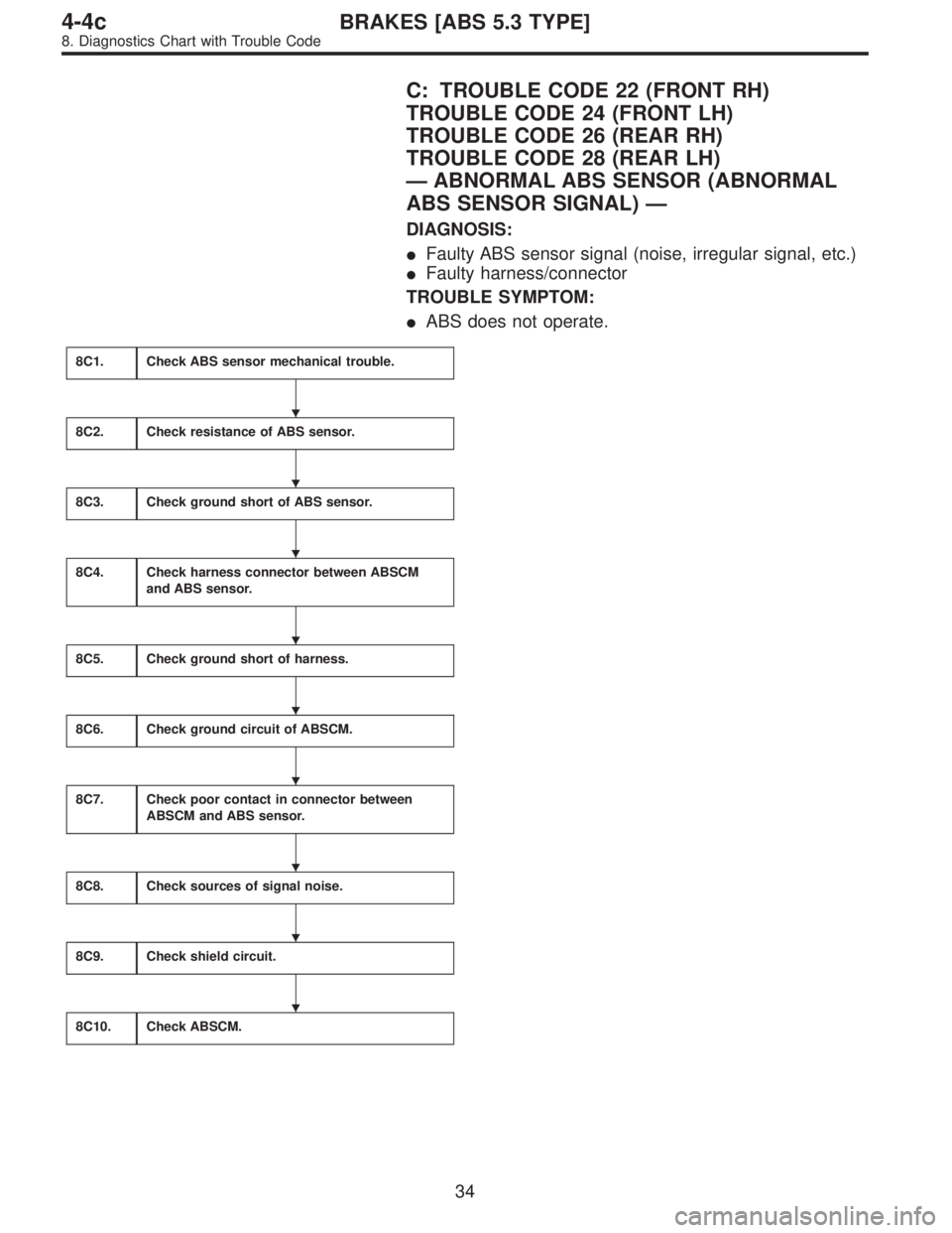
C: TROUBLE CODE 22 (FRONT RH)
TROUBLE CODE 24 (FRONT LH)
TROUBLE CODE 26 (REAR RH)
TROUBLE CODE 28 (REAR LH)
—ABNORMAL ABS SENSOR (ABNORMAL
ABS SENSOR SIGNAL)—
DIAGNOSIS:
�Faulty ABS sensor signal (noise, irregular signal, etc.)
�Faulty harness/connector
TROUBLE SYMPTOM:
�ABS does not operate.
8C1.Check ABS sensor mechanical trouble.
8C2.Check resistance of ABS sensor.
8C3.Check ground short of ABS sensor.
8C4.Check harness connector between ABSCM
and ABS sensor.
8C5.Check ground short of harness.
8C6.Check ground circuit of ABSCM.
8C7.Check poor contact in connector between
ABSCM and ABS sensor.
8C8.Check sources of signal noise.
8C9.Check shield circuit.
8C10.Check ABSCM.
�
�
�
�
�
�
�
�
�
34
4-4cBRAKES [ABS 5.3 TYPE]
8. Diagnostics Chart with Trouble Code
![SUBARU LEGACY 1996 Service Repair Manual WIRING DIAGRAM:
B4M1035
29
4-4cBRAKES [ABS 5.3 TYPE]
8. Diagnostics Chart with Trouble Code](/manual-img/17/57433/w960_57433-2368.png "SUBARU LEGACY 1996 Service Repair Manual WIRING DIAGRAM:
B4M1035
29
4-4cBRAKES [ABS 5.3 TYPE]
8. Diagnostics Chart with Trouble Code")
 Connec")