Page 1561 of 2890
![SUBARU LEGACY 1996 Service Repair Manual B5M0045
8. REAR QUARTER PILLAR LOWER
<Ref. to 5-3 [C500].>
1) Set rear seat cushion up.
2) Remove side sill rear upper cover.
3) Remove rear seat belt. (Upper anchor and lower anchor
bolts)
4) Remove SUBARU LEGACY 1996 Service Repair Manual B5M0045
8. REAR QUARTER PILLAR LOWER
<Ref. to 5-3 [C500].>
1) Set rear seat cushion up.
2) Remove side sill rear upper cover.
3) Remove rear seat belt. (Upper anchor and lower anchor
bolts)
4) Remove](/manual-img/17/57433/w960_57433-1560.png)
B5M0045
8. REAR QUARTER PILLAR LOWER
1) Set rear seat cushion up.
2) Remove side sill rear upper cover.
3) Remove rear seat belt. (Upper anchor and lower anchor
bolts)
4) Remove side skirt trim.
5) Remove cap strut.
6) Remove rear quarter upper rear trim.
7) Remove rear quarter pillar lower trim.
8) Installation is in the reverse order of removal.
CAUTION:
Be careful not to ride trim panel over harness,
insulators, etc.
B5M0050
9. ROOF TRIM
1) Remove room mirror, room light, sun visor and assist
grip.
2) Remove front pillar upper, center pillar upper, rear quar-
ter upper and rear rail trim.
3) Using ST, remove clips and then detach roof trim.
ST 925580000 PULLER
4) Installation is in the reverse order of removal.
CAUTION:
When removing clip, use great care to prevent damag-
ing the roof trim.
10. FLOOR MAT
Supplemental Restraint System“Airbag”
Airbag system wiring harness is routed near floor mat.
CAUTION:
�All Airbag system wiring harness and connectors
are colored yellow. Do not use electrical test equip-
ment on these circuit.
�Be careful not to damage Airbag system wiring har-
ness when servicing floor mat.
The following procedure is applicable to all models.
15
5-3SERVICE PROCEDURE
5. Inner Trim Panel
Page 1647 of 2890
![SUBARU LEGACY 1996 Service Repair Manual B6M0575A
5) Move washer tank upward.
B6M0563A
6) Remove #4 spark plug cord by pulling boot, not cord
itself.
7) For subsequent procedures, refer to the procedure for
#1 spark plug. <Ref. to 6-1 [W3E1] SUBARU LEGACY 1996 Service Repair Manual B6M0575A
5) Move washer tank upward.
B6M0563A
6) Remove #4 spark plug cord by pulling boot, not cord
itself.
7) For subsequent procedures, refer to the procedure for
#1 spark plug. <Ref. to 6-1 [W3E1]](/manual-img/17/57433/w960_57433-1646.png)
B6M0575A
5) Move washer tank upward.
B6M0563A
6) Remove #4 spark plug cord by pulling boot, not cord
itself.
7) For subsequent procedures, refer to the procedure for
#1 spark plug.
CAUTION:
When removing spark plug, cover the ATF coolig pipes
with a rag to prevent damage.
B6M0572A
NOTE:
For easier removal of spark plug, diagonally insert the tools
from the direction of battery stand into plug hole as shown
in figure.
B6M0573
F: INSTALLATION (2500 cc OUTBACK
MODEL)
1. #1 SPARK PLUG
1) After setting spark plug in spark plug socket, connect
the spark plug socket, extension and Universal Joint to
each other.
2) Screw spark plug into cylinder head using the con-
nected tools above mentioned. At this point, it is necessary
to support the rear end of the tools with fingertips.
3) When spark plug is screwed in two or three turns, tem-
porarily disconnect the tools connected in step 1) above.
4) Confirm that spark plug is screwed into the cylinder
head properly by touching it with finger. If it is difficult to
reach it by hand, confirm its condition by using mirror and
suchlike.
5) Cover ABS pipes with rag to prevent damage.
33
6-1SERVICE PROCEDURE
3. Spark Plug
Page 1704 of 2890
![SUBARU LEGACY 1996 Service Repair Manual B6M0133
B: INSPECTION
1. DOOR LOCK SWITCH (DRIVER’S DOOR)
1) Remove door trim panel. <Ref. to 5-2 [W2A2].>
2) Disconnect connector of door switch.
3) Set switch to each position and check continuity SUBARU LEGACY 1996 Service Repair Manual B6M0133
B: INSPECTION
1. DOOR LOCK SWITCH (DRIVER’S DOOR)
1) Remove door trim panel. <Ref. to 5-2 [W2A2].>
2) Disconnect connector of door switch.
3) Set switch to each position and check continuity](/manual-img/17/57433/w960_57433-1703.png)
B6M0133
B: INSPECTION
1. DOOR LOCK SWITCH (DRIVER’S DOOR)
1) Remove door trim panel.
2) Disconnect connector of door switch.
3) Set switch to each position and check continuity
between terminals as indicated in table below:
Terminal
Switch position12
UNLOCK��
LOCK
B6M0135
2. ACTUATOR
1) Remove door trim panel.
2) Disconnect connector of actuator.
3) Make sure that door link moves to LOCK or UNLOCK
position when battery voltage is applied between terminals
as described below:
�Connect battery positive (+) terminal to terminal No. 2,
and negative (�) terminal to terminal No. 4 at a moment.
�Connect battery positive (+) terminal to terminal No. 4,
and negative terminal (�) to terminal No. 2 at a moment.
B6M0352A
18. Remote Controlled Rearview Mirror
A: REMOVAL AND INSTALLATION
1. REMOTE CONTROLLED REARVIEW MIRROR
SWITCH
1) Remove rearview mirror switch from instrument panel
by using a small standard screwdriver.
CAUTION:
Do not pry rearview mirror switch forcefully as this
may scratch instrument panel.
2) Remove rearview mirror switch while disconnecting
connector.
42
6-2SERVICE PROCEDURE
17. Power Door Lock - 18. Remote Controlled Rearview Mirror
Page 1705 of 2890
![SUBARU LEGACY 1996 Service Repair Manual B6M0133
B: INSPECTION
1. DOOR LOCK SWITCH (DRIVER’S DOOR)
1) Remove door trim panel. <Ref. to 5-2 [W2A2].>
2) Disconnect connector of door switch.
3) Set switch to each position and check continuity SUBARU LEGACY 1996 Service Repair Manual B6M0133
B: INSPECTION
1. DOOR LOCK SWITCH (DRIVER’S DOOR)
1) Remove door trim panel. <Ref. to 5-2 [W2A2].>
2) Disconnect connector of door switch.
3) Set switch to each position and check continuity](/manual-img/17/57433/w960_57433-1704.png)
B6M0133
B: INSPECTION
1. DOOR LOCK SWITCH (DRIVER’S DOOR)
1) Remove door trim panel.
2) Disconnect connector of door switch.
3) Set switch to each position and check continuity
between terminals as indicated in table below:
Terminal
Switch position12
UNLOCK��
LOCK
B6M0135
2. ACTUATOR
1) Remove door trim panel.
2) Disconnect connector of actuator.
3) Make sure that door link moves to LOCK or UNLOCK
position when battery voltage is applied between terminals
as described below:
�Connect battery positive (+) terminal to terminal No. 2,
and negative (�) terminal to terminal No. 4 at a moment.
�Connect battery positive (+) terminal to terminal No. 4,
and negative terminal (�) to terminal No. 2 at a moment.
B6M0352A
18. Remote Controlled Rearview Mirror
A: REMOVAL AND INSTALLATION
1. REMOTE CONTROLLED REARVIEW MIRROR
SWITCH
1) Remove rearview mirror switch from instrument panel
by using a small standard screwdriver.
CAUTION:
Do not pry rearview mirror switch forcefully as this
may scratch instrument panel.
2) Remove rearview mirror switch while disconnecting
connector.
42
6-2SERVICE PROCEDURE
17. Power Door Lock - 18. Remote Controlled Rearview Mirror
Page 1706 of 2890
B6M0137
2. REARVIEW MIRROR
1) Remove door trim panel.
2) Disconnect connector of rearview mirror.
3) Remove screws which secure rearview mirror, and then
remove rearview mirror.
B6M0139A
B: INSPECTION
1. REARVIEW MIRROR SWITCH
Move rearview mirror switch to each position and check
continuity between terminals as indicated in table below:
Switch
position
TerminalMirror switch Left/Right changing switch
OFF Right Left Up Down Left N Right
7�
9�
6�
8�
2����
����
1�
���
��� �
4����
3
B6M0140
2. REARVIEW MIRROR
Check to ensure that rearview mirror moves properly when
battery voltage is applied to terminals as indicated in table
below:
OperationTerminal connection
(+) (�)
UP 3 1
DOWN 1 3
RIGHT 1 2
LEFT 2 1
43
6-2SERVICE PROCEDURE
18. Remote Controlled Rearview Mirror
Page 1747 of 2890

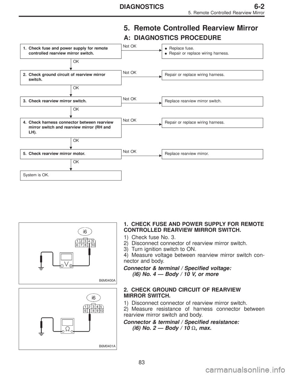
5. Remote Controlled Rearview Mirror
A: DIAGNOSTICS PROCEDURE
1. Check fuse and power supply for remote
controlled rearview mirror switch.
OK
�Not OK
�Replace fuse.
�Repair or replace wiring harness.
2. Check ground circuit of rearview mirror
switch.
OK
�Not OK
Repair or replace wiring harness.
3. Check rearview mirror switch.
OK
�Not OK
Replace rearview mirror switch.
4. Check harness connector between rearview
mirror switch and rearview mirror (RH and
LH).
OK
�Not OK
Repair or replace wiring harness.
5. Check rearview mirror motor.
OK
�Not OK
Replace rearview mirror.
System is OK.
B6M0400A
1. CHECK FUSE AND POWER SUPPLY FOR REMOTE
CONTROLLED REARVIEW MIRROR SWITCH.
1) Check fuse No. 3.
2) Disconnect connector of rearview mirror switch.
3) Turn ignition switch to ON.
4) Measure voltage between rearview mirror switch con-
nector and body.
Connector & terminal / Specified voltage:
(i6) No. 4—Body / 10 V, or more
B6M0401A
2. CHECK GROUND CIRCUIT OF REARVIEW
MIRROR SWITCH.
1) Disconnect connector of rearview mirror switch.
2) Measure resistance of harness connector between
rearview mirror switch and body.
Connector & terminal / Specified resistance:
(i6) No. 2—Body / 10Ω, max.
�
�
�
�
�
83
6-2DIAGNOSTICS
5. Remote Controlled Rearview Mirror
Page 1748 of 2890
![SUBARU LEGACY 1996 Service Repair Manual 3. CHECK REARVIEW MIRROR SWITCH.
Refer to 6-2 [W18B1] for inspection of rearview mirror
switch.
B6M0402A
B6M0469A
4. CHECK HARNESS CONNECTOR BETWEEN
REARVIEW MIRROR SWITCH AND REARVIEW
MIRROR (RH AND SUBARU LEGACY 1996 Service Repair Manual 3. CHECK REARVIEW MIRROR SWITCH.
Refer to 6-2 [W18B1] for inspection of rearview mirror
switch.
B6M0402A
B6M0469A
4. CHECK HARNESS CONNECTOR BETWEEN
REARVIEW MIRROR SWITCH AND REARVIEW
MIRROR (RH AND](/manual-img/17/57433/w960_57433-1747.png)
3. CHECK REARVIEW MIRROR SWITCH.
Refer to 6-2 [W18B1] for inspection of rearview mirror
switch.
B6M0402A
B6M0469A
4. CHECK HARNESS CONNECTOR BETWEEN
REARVIEW MIRROR SWITCH AND REARVIEW
MIRROR (RH AND LH).
1) Disconnect connectors of rearview mirror switch and
rearview mirror.
2) Measure resistance of harness connector between
rearview mirror switch and rearview mirror.
Connector & terminal / Specified resistance:
LHD model:
(i6) No. 1—(D15) No.1/10Ω, max. (RH)
(i6) No. 8—(D15) No.2/10Ω, max. (RH)
(i6) No. 6—(D15) No.3/10Ω, max. (RH)
(i6) No. 1—(D5)No.1/10Ω, max. (LH)
(i6) No. 9—(D5)No.2/10Ω, max. (LH)
(i6) No. 7—(D5)No.3/10Ω, max. (LH)
RHD model:
(i6) No. 1—(D5) No.1/10Ω, max. (RH)
(i6) No. 8—(D5) No.2/10Ω, max. (RH)
(i6) No. 6—(D5) No.3/10Ω, max. (RH)
(i6) No. 1—(D15) No.1/10Ω, max. (LH)
(i6) No. 9—(D15) No.2/10Ω, max. (LH)
(i6) No. 7—(D15) No.3/10Ω, max. (LH)
5. CHECK REARVIEW MIRROR MOTOR.
Refer to 6-2 [W18B2] for inspection of rearview mirror
motor.
84
6-2DIAGNOSTICS
5. Remote Controlled Rearview Mirror
Page 2750 of 2890

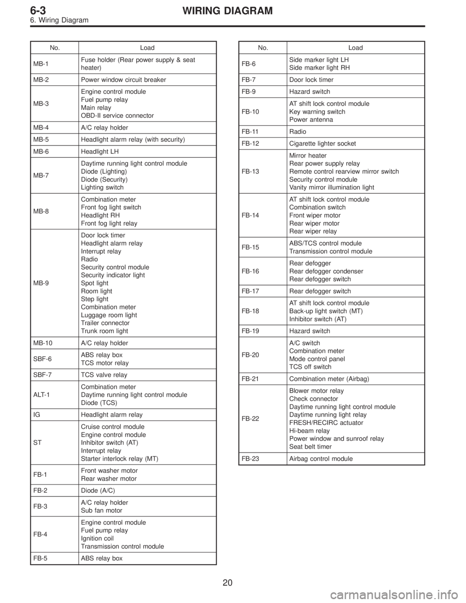
No. Load
MB-1Fuse holder (Rear power supply & seat
heater)
MB-2 Power window circuit breaker
MB-3Engine control module
Fuel pump relay
Main relay
OBD-II service connector
MB-4 A/C relay holder
MB-5 Headlight alarm relay (with security)
MB-6 Headlight LH
MB-7Daytime running light control module
Diode (Lighting)
Diode (Security)
Lighting switch
MB-8Combination meter
Front fog light switch
Headlight RH
Front fog light relay
MB-9Door lock timer
Headlight alarm relay
Interrupt relay
Radio
Security control module
Security indicator light
Spot light
Room light
Step light
Combination meter
Luggage room light
Trailer connector
Trunk room light
MB-10 A/C relay holder
SBF-6ABS relay box
TCS motor relay
SBF-7 TCS valve relay
ALT-1Combination meter
Daytime running light control module
Diode (TCS)
IG Headlight alarm relay
STCruise control module
Engine control module
Inhibitor switch (AT)
Interrupt relay
Starter interlock relay (MT)
FB-1Front washer motor
Rear washer motor
FB-2 Diode (A/C)
FB-3A/C relay holder
Sub fan motor
FB-4Engine control module
Fuel pump relay
Ignition coil
Transmission control module
FB-5 ABS relay boxNo. Load
FB-6Side marker light LH
Side marker light RH
FB-7 Door lock timer
FB-9 Hazard switch
FB-10AT shift lock control module
Key warning switch
Power antenna
FB-11 Radio
FB-12 Cigarette lighter socket
FB-13Mirror heater
Rear power supply relay
Remote control rearview mirror switch
Security control module
Vanity mirror illumination light
FB-14AT shift lock control module
Combination switch
Front wiper motor
Rear wiper motor
Rear wiper relay
FB-15ABS/TCS control module
Transmission control module
FB-16Rear defogger
Rear defogger condenser
Rear defogger switch
FB-17 Rear defogger switch
FB-18AT shift lock control module
Back-up light switch (MT)
Inhibitor switch (AT)
FB-19 Hazard switch
FB-20A/C switch
Combination meter
Mode control panel
TCS off switch
FB-21 Combination meter (Airbag)
FB-22Blower motor relay
Check connector
Daytime running light control module
Daytime running light relay
FRESH/RECIRC actuator
Hi-beam relay
Power window and sunroof relay
Seat belt timer
FB-23 Airbag control module
20
6-3WIRING DIAGRAM
6. Wiring Diagram