Page 739 of 2890
G2M0267
(5) Connect radiator inlet hose.
B2M0016A
(6) Connect radiator outlet hose.
(7) Connect ATF cooler hoses. (AT model)
B2M0017
(8) Install V-belt cover.
16) Install battery in the vehicle, and connect cables.
17) Fill coolant.
18) Check ATF level and correct if necessary. (AT model)
19) Charge A/C system with refrigerant.
20) Remove front hood stay, and close front hood.
21) Take off the vehicle from lift arms.
26
2-11SERVICE PROCEDURE
2. Engine
Page 829 of 2890

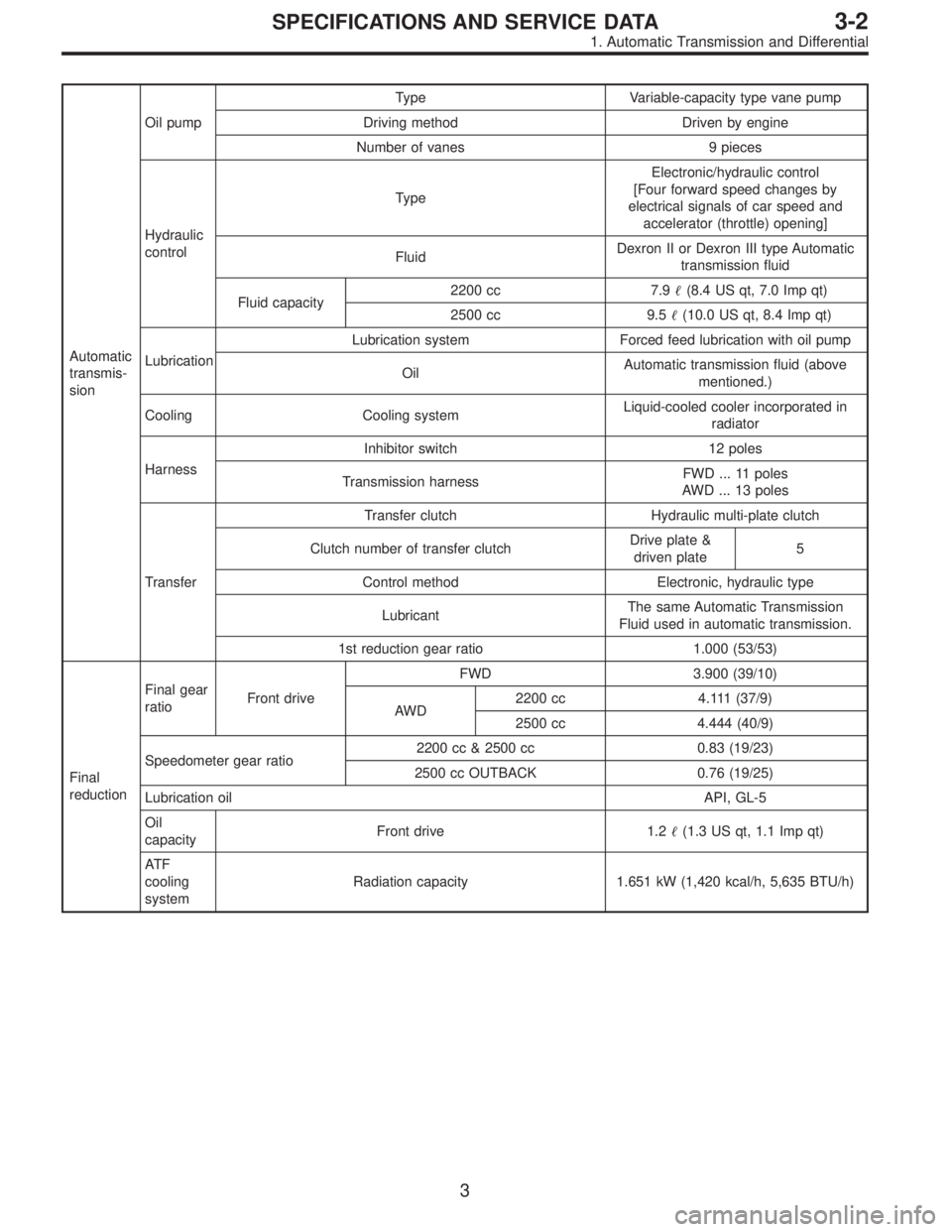
Automatic
transmis-
sionOil pumpType Variable-capacity type vane pump
Driving method Driven by engine
Number of vanes 9 pieces
Hydraulic
controlTypeElectronic/hydraulic control
[Four forward speed changes by
electrical signals of car speed and
accelerator (throttle) opening]
FluidDexron II or Dexron III type Automatic
transmission fluid
Fluid capacity2200 cc 7.9�(8.4 US qt, 7.0 Imp qt)
2500 cc 9.5�(10.0 US qt, 8.4 Imp qt)
LubricationLubrication system Forced feed lubrication with oil pump
OilAutomatic transmission fluid (above
mentioned.)
Cooling Cooling systemLiquid-cooled cooler incorporated in
radiator
HarnessInhibitor switch 12 poles
Transmission harnessFWD ... 11 poles
AWD ... 13 poles
TransferTransfer clutch Hydraulic multi-plate clutch
Clutch number of transfer clutchDrive plate &
driven plate5
Control method Electronic, hydraulic type
LubricantThe same Automatic Transmission
Fluid used in automatic transmission.
1st reduction gear ratio 1.000 (53/53)
Final
reductionFinal gear
ratioFront driveFWD 3.900 (39/10)
AWD2200 cc 4.111 (37/9)
2500 cc 4.444 (40/9)
Speedometer gear ratio2200 cc & 2500 cc 0.83 (19/23)
2500 cc OUTBACK 0.76 (19/25)
Lubrication oilAPI, GL-5
Oil
capacityFront drive 1.2�(1.3 US qt, 1.1 Imp qt)
AT F
cooling
systemRadiation capacity 1.651 kW (1,420 kcal/h, 5,635 BTU/h)
3
3-2SPECIFICATIONS AND SERVICE DATA
1. Automatic Transmission and Differential
Page 1375 of 2890

1. Air Conditioning System
A: SPECIFICATIONS
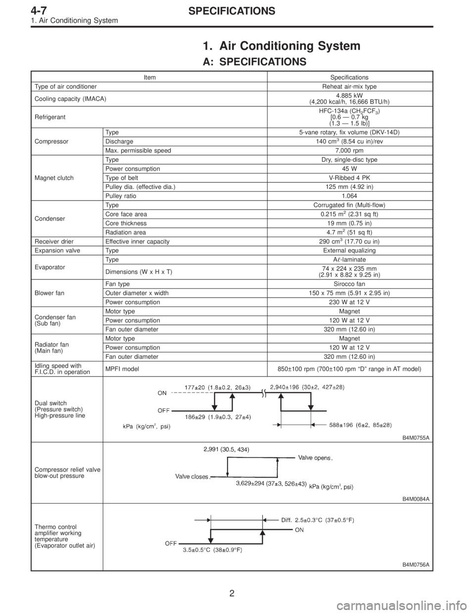
Item Specifications
Type of air conditionerReheat air-mix type
Cooling capacity (IMACA)4.885 kW
(4,200 kcal/h, 16,666 BTU/h)
RefrigerantHFC-134a (CH
2FCF3)
[0.6 — 0.7 kg
(1.3 — 1.5 lb)]
CompressorType 5-vane rotary, fix volume (DKV-14D)
Discharge 140 cm
3(8.54 cu in)/rev
Max. permissible speed 7,000 rpm
Magnet clutchTy p eDry, single-disc type
Power consumption 45 W
Type of belt V-Ribbed 4 PK
Pulley dia. (effective dia.) 125 mm (4.92 in)
Pulley ratio1.064
CondenserType Corrugated fin (Multi-flow)
Core face area 0.215 m
2(2.31 sq ft)
Core thickness 19 mm (0.75 in)
Radiation area 4.7 m
2(51 sq ft)
Receiver drier Effective inner capacity 290 cm3(17.70 cu in)
Expansion valve TypeExternal equalizing
EvaporatorTy p eA�-laminate
Dimensions (W x H x T)74 x 224 x 235 mm
(2.91 x 8.82 x 9.25 in)
Blower fanFan typeSirocco fan
Outer diameter x width 150 x 75 mm (5.91 x 2.95 in)
Power consumption 230 W at 12 V
Condenser fan
(Sub fan)Motor typeMagnet
Power consumption 120 W at 12 V
Fan outer diameter 320 mm (12.60 in)
Radiator fan
(Main fan)Motor typeMagnet
Power consumption 120 W at 12 V
Fan outer diameter 320 mm (12.60 in)
Idling speed with
F.I.C.D. in operationMPFI model 850±100 rpm (700±100 rpm “D” range in AT model)
Dual switch
(Pressure switch)
High-pressure line
B4M0755A
Compressor relief valve
blow-out pressure
B4M0084A
Thermo control
amplifier working
temperature
(Evaporator outlet air)
B4M0756A
2
4-7SPECIFICATIONS
1. Air Conditioning System
Page 1409 of 2890
B4M0095
12. Condenser
A: REMOVAL AND INSTALLATION
1) Disconnect battery negative terminal.
2) Discharge refrigerant using refrigerant recovery system.
3) Remove front grille.
G2M0375
4) Remove canister from bracket.
CAUTION:
�Do not disconnect hose from canister.
�Insert air vent hose of canister into the hole on body.
B4M0096A
5) Remove the radiator upper bracket of both side.
6) Disconnect high-pressure hose�
1and high-pressure
pipe�
2from condenser.
B4M0097
7) Remove the two bolts which secure condenser. While
lifting condenser, remove it through space between radia-
tor and radiator panel.
B4M0098A
8) The condenser should be installed in the reverse order
in which it was removed.
When installing the condenser, pay attention to the follow-
ing:
CAUTION:
Before connecting the pipe, be sure to apply oil to the
periphery of O-ring.
35
4-7SERVICE PROCEDURE
12. Condenser
Page 1410 of 2890
![SUBARU LEGACY 1996 Service Repair Manual NOTE:
After installing condenser, ensure that guide on lower side
of condenser is inserted into hole in radiator panel. Tighten
attaching bolts.
9) Charge refrigerant. <Ref. to 4-7 [W708].>
B: INSPECT SUBARU LEGACY 1996 Service Repair Manual NOTE:
After installing condenser, ensure that guide on lower side
of condenser is inserted into hole in radiator panel. Tighten
attaching bolts.
9) Charge refrigerant. <Ref. to 4-7 [W708].>
B: INSPECT](/manual-img/17/57433/w960_57433-1409.png)
NOTE:
After installing condenser, ensure that guide on lower side
of condenser is inserted into hole in radiator panel. Tighten
attaching bolts.
9) Charge refrigerant.
B: INSPECTION
1) Make sure the condenser fins are free from dust and
insects. If the fins are clogged, clean by blowing air or
water through them.
NOTE:
To prevent dust and water from getting into the condenser,
this work must be done when the condenser is installed in
an actual vehicle.
2) Check the condenser to see if it shows any sign of oil.
Should oil ooze or gas leak from the condenser replace it
with a new one.
G4M0640
13. Receiver Drier
A: REMOVAL AND INSTALLATION
1) Disconnect battery negative terminal.
2) Discharge refrigerant using refrigerant recovery system.
3) Disconnect pressure switch harness�
1.
4) Disconnect pipes�
2.
5) Remove mounting bolt�
3and remove receiver drier.
CAUTION:
The receiver drier contains a desiccant. Be sure to put
a blind plug in the detached receiver drier to protect it
from moisture.
6) Install the receiver drier in the reverse order of removal.
7) Charge refrigerant.
36
4-7SERVICE PROCEDURE
12. Condenser - 13. Receiver Drier
Page 1411 of 2890
![SUBARU LEGACY 1996 Service Repair Manual NOTE:
After installing condenser, ensure that guide on lower side
of condenser is inserted into hole in radiator panel. Tighten
attaching bolts.
9) Charge refrigerant. <Ref. to 4-7 [W708].>
B: INSPECT SUBARU LEGACY 1996 Service Repair Manual NOTE:
After installing condenser, ensure that guide on lower side
of condenser is inserted into hole in radiator panel. Tighten
attaching bolts.
9) Charge refrigerant. <Ref. to 4-7 [W708].>
B: INSPECT](/manual-img/17/57433/w960_57433-1410.png)
NOTE:
After installing condenser, ensure that guide on lower side
of condenser is inserted into hole in radiator panel. Tighten
attaching bolts.
9) Charge refrigerant.
B: INSPECTION
1) Make sure the condenser fins are free from dust and
insects. If the fins are clogged, clean by blowing air or
water through them.
NOTE:
To prevent dust and water from getting into the condenser,
this work must be done when the condenser is installed in
an actual vehicle.
2) Check the condenser to see if it shows any sign of oil.
Should oil ooze or gas leak from the condenser replace it
with a new one.
G4M0640
13. Receiver Drier
A: REMOVAL AND INSTALLATION
1) Disconnect battery negative terminal.
2) Discharge refrigerant using refrigerant recovery system.
3) Disconnect pressure switch harness�
1.
4) Disconnect pipes�
2.
5) Remove mounting bolt�
3and remove receiver drier.
CAUTION:
The receiver drier contains a desiccant. Be sure to put
a blind plug in the detached receiver drier to protect it
from moisture.
6) Install the receiver drier in the reverse order of removal.
7) Charge refrigerant.
36
4-7SERVICE PROCEDURE
12. Condenser - 13. Receiver Drier
Page 1413 of 2890

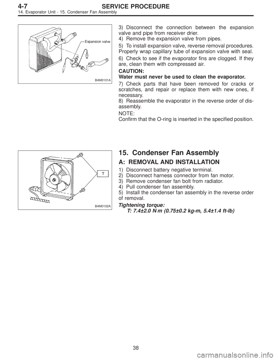
B4M0101A
3) Disconnect the connection between the expansion
valve and pipe from receiver drier.
4) Remove the expansion valve from pipes.
5) To install expansion valve, reverse removal procedures.
Properly wrap capillary tube of expansion valve with seal.
6) Check to see if the evaporator fins are clogged. If they
are, clean them with compressed air.
CAUTION:
Water must never be used to clean the evaporator.
7) Check parts that have been removed for cracks or
scratches, and repair or replace them with new ones, if
necessary.
8) Reassemble the evaporator in the reverse order of dis-
assembly.
NOTE:
Confirm that the O-ring is inserted in the specified position.
B4M0102A
15. Condenser Fan Assembly
A: REMOVAL AND INSTALLATION
1) Disconnect battery negative terminal.
2) Disconnect harness connector from fan motor.
3) Remove condenser fan bolt from radiator.
4) Pull condenser fan assembly.
5) Install the condenser fan assembly in the reverse order
of removal.
Tightening torque:
T: 7.4±2.0 N⋅m (0.75±0.2 kg-m, 5.4±1.4 ft-lb)
38
4-7SERVICE PROCEDURE
14. Evaporator Unit - 15. Condenser Fan Assembly
Page 1414 of 2890

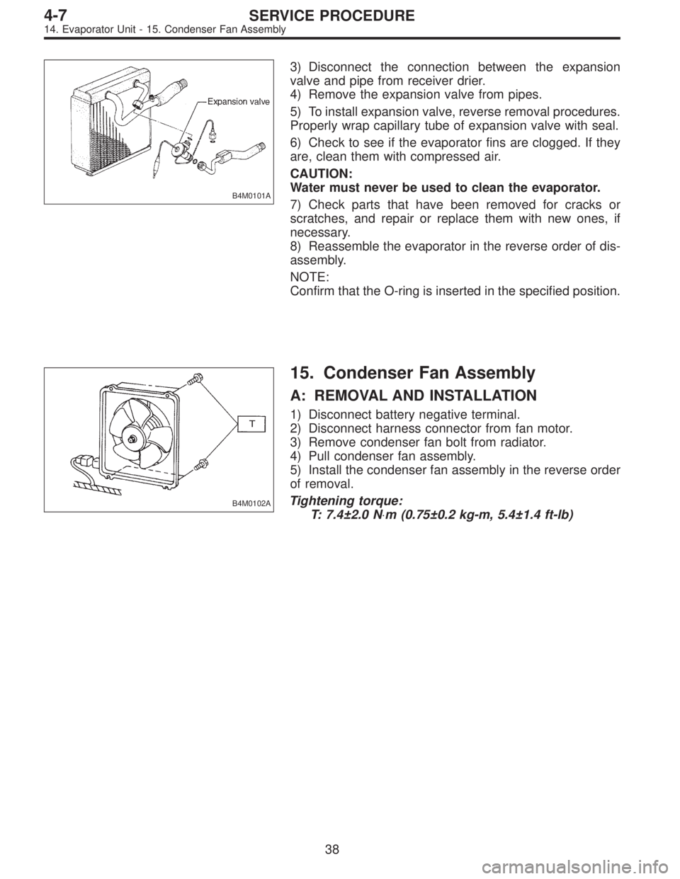
B4M0101A
3) Disconnect the connection between the expansion
valve and pipe from receiver drier.
4) Remove the expansion valve from pipes.
5) To install expansion valve, reverse removal procedures.
Properly wrap capillary tube of expansion valve with seal.
6) Check to see if the evaporator fins are clogged. If they
are, clean them with compressed air.
CAUTION:
Water must never be used to clean the evaporator.
7) Check parts that have been removed for cracks or
scratches, and repair or replace them with new ones, if
necessary.
8) Reassemble the evaporator in the reverse order of dis-
assembly.
NOTE:
Confirm that the O-ring is inserted in the specified position.
B4M0102A
15. Condenser Fan Assembly
A: REMOVAL AND INSTALLATION
1) Disconnect battery negative terminal.
2) Disconnect harness connector from fan motor.
3) Remove condenser fan bolt from radiator.
4) Pull condenser fan assembly.
5) Install the condenser fan assembly in the reverse order
of removal.
Tightening torque:
T: 7.4±2.0 N⋅m (0.75±0.2 kg-m, 5.4±1.4 ft-lb)
38
4-7SERVICE PROCEDURE
14. Evaporator Unit - 15. Condenser Fan Assembly