Page 1839 of 2890

Note
Ignition SW ON
(Engine OFF)Engine ON (Idling)
Knock
sensorSignal B84 3 2.8 2.8—
Shield B84 56 0 0—
AT/MT identification B84 81(AT) 5
(MT) 0(AT) 5
(M")
ContentConnector
No.Terminal
No.Signal (V)
Note
Ignition SW ON
(Engine OFF)Engine ON (Idling)
Knock
sensorSignal B84 3 2.8 2.8—
Shield B84 56 0 0—
AT/MT identification B84 81(AT) 5
(MT) 0(AT) 5
(MT) 0When measuring voltage between
ECM and body.
Back-up power supply B84 39 10—13 13—14 Ignition switch“OFF”:10—13
Control unit power supply B841
10—13 13—14—
2
Ignition
control#1,#2 B84 41 0 1—3.4—
#3,#4 B84 40 0 1—3.4—
Fuel
injector# 1 B84 96 10—13 1—14 Waveform
# 2 B84 70 10—13 1—14 Waveform
# 3 B84 44 10—13 1—14 Waveform
# 4 B84 16 10—13 1—14 Waveform
Idle air
control
solenoid
valveOPEN end B84 14—1—13 Waveform
CLOSE end B84 13—13—1 Waveform
Fuel pump relay control B84 32ON: 0.5, or less
OFF: 10—130.5, or less—
A/C relay control B84 31ON: 0.5, or less
OFF: 10—13ON: 0.5, or less
OFF: 13—14—
Radiator fan relay 1
controlB84 74ON: 0.5, or less
OFF: 10—13ON: 0.5, or less
OFF: 13—14—
Radiator fan relay 2
controlB84 73ON: 0.5, or less
OFF: 10—13ON: 0.5, or less
OFF: 13—14With A/C vehicles only
Self-shutoff control B84 63 10—13 13—14—
Malfunction indicator lamp B84 58——Light“ON”:1,orless
Light“OFF”:10—14
Engine speed output B84 64—0—13, or more Waveform
Torque control signal B84 79 5 5—
Mass air flow signal for
ATB84 47 0—0.3 0.8—1.2—
Purge control solenoid
valveB84 72ON: 1, or less
OFF: 10—13ON: 1, or less
OFF: 13—14—
Atmospheric pressure
sensorB84 26 3.9—4.1 2.0—2.3—
Pressure sources
switching solenoid valveB84 15ON: 1, or less
OFF: 10—13ON: 1, or less
OFF: 13—14—
EGR solenoid valve B84 71ON: 1, or less
OFF: 10—13ON: 1, or less
OFF: 13—14—
Front oxygen sensor
heater signalB84 38 0—1.0 0—1.0—
Rear oxygen sensor
heater signalB84 37 0—1.0 0—1.0—
Fuel temperature sensor B84 25 2.5—3.8 2.5—3.8�2200 cc AWD except Taiwan
model
�Ambient temperature: 25°C
(77°F)
Fuel level sensor B84 27 0.12—4.75 0.12—4.75 2200 cc AWD except Taiwan model
Fuel tank
pressure
sensorSignal B84 4 2.3—2.7 2.3—2.7�2200 cc AWD except Taiwan
model
�The value obtained after the fuel
filler cap was removed once and
recapped.
Power
supplyB84 21 5 5—
GND B84 20 0 0—
Fuel tank pressure control
solenoid valveB84 10ON: 1, or less
OFF: 10—13ON: 1, or less
OFF: 13—142200 cc AWD except Taiwan model
Vent control solenoid
valveB84 35ON: 1, or less
OFF: 10—13ON: 1, or less
OFF: 13—142200 cc AWD except Taiwan model
TCS signal B84 61 0—70—7 Waveform
71
2-7ON-BOARD DIAGNOSTICS II SYSTEM
5. Specified Data
Page 1892 of 2890
Item Page
P0500 VSP Vehicle speed sensor malfunction 266
P0505 ISC Idle control system malfunction 269
P0506 ISC
—L Idle control system RPM lower than expe")
DTC
No.Abbreviation
(Subaru select monitor)Item Page
P0500 VSP Vehicle speed sensor malfunction 266
P0505 ISC Idle control system malfunction 269
P0506 ISC
—L Idle control system RPM lower than expected 276
P0507 ISC
—H Idle control system RPM higher than expected 277
P0600—Serial communication link malfunction 278
P0601 RAM Internal control module memory check sum error 281
P0703 ATBRK Brake switch input malfunction 283
P0705 ATRNG Transmission range sensor circuit malfunction 286
P0710 ATF Transmission fluid temperature sensor circuit malfunction 293
P0720 ATVSP Output speed sensor (vehicle speed sensor 1) circuit malfunction 294
P0725 ATNE Engine speed input circuit malfunction 295
P0731 ATGR1 Gear 1 incorrect ratio
296 P0732 ATGR2 Gear 2 incorrect ratio
P0733 ATGR3 Gear 3 incorrect ratio
P0734 ATGR4 Gear 4 incorrect ratio
P0740 ATLU
—F Torque converter clutch system malfunction 300
P0743 ATLU Torque converter clutch system electrical 304
P0748 ATPL Pressure control solenoid electrical 305
P0753 ATSFT1 Shift solenoid A electrical 306
P0758 ATSFT2 Shift solenoid B electrical 307
P0760 ATOVR
—F Shift solenoid C malfunction 308
P0763 ATOVR Shift solenoid C electrical 312
P1100 ST
—SW Starter switch circuit malfunction 313
P1101 N/P
—SW Neutral position switch circuit malfunction [MT vehicles] 315
P1101 N/P
—SW Neutral position switch circuit malfunction [AT vehicles] 318
P1102 BR Pressure sources switching solenoid valve circuit malfunction 322
P1103 TRQ Engine torque control signal circuit malfunction 328
P1400 PCVSOL Fuel tank pressure control solenoid valve circuit malfunction 331
P1401 PCV
—F Fuel tank pressure control system function problem 337
P1402 FLVL Fuel level sensor circuit malfunction 339
P1500 FAN
—1 Radiator fan relay 1 circuit malfunction 351
P1502 FAN
—F Radiator fan function problem 358
P1700 ATTH Throttle position sensor circuit malfunction for automatic transmission 361
P1701 ATCRS Cruise control set signal circuit malfunction for automatic transmission 362
P1702 ATDIAG Automatic transmission diagnosis input signal circuit malfunction 365
P0461*1 EXERR22 Fuel level sensor circuit range/performance problem 368
*1: Only OBD-II general scan tool displays DTC.
124
2-7ON-BOARD DIAGNOSTICS II SYSTEM
10. Diagnostics Chart with Trouble Code
Page 1994 of 2890
OBD0145A
CONFIRMATION OF ACTUAL DRIVING
PATTERN.
1) Conduct CLEAR MEMORY and INSPECTION MODES.
2) Connect Subaru select monitor to its data link connec-
tor.
3) Start and warm-up the engine until the radiator fan
makes one complete rotation. (All accessory switches are
OFF.)
4) Turn Subaru select monitor switch to ON.
G3M0152
5) Designate mode using function key.
Function mode: FA4
B2M0564
6) Drive at 88±5 km/h (55±3 MPH) until the LED No. 2
comes on.
NOTE:
Keep the throttle valve opening at the same degree, since
diagnosis will be interrupted when the opening varies.
Diagnosis starts in 190 seconds after starting engine and
takes 4 seconds.
Put the gear to“D”range for the diagnosis.
H2M1206
7) Designate mode using function key.
Function mode: FB0
8) Confirm the“No trouble”indication on Subaru select
monitor.
226
2-7ON-BOARD DIAGNOSTICS II SYSTEM
10. Diagnostics Chart with Trouble Code
Page 2119 of 2890
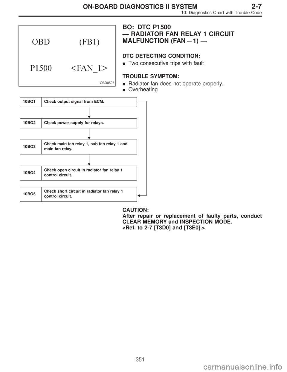
OBD0527
BQ: DTC P1500
—RADIATOR FAN RELAY 1 CIRCUIT
MALFUNCTION (FAN
—1)—
DTC DETECTING CONDITION:
�Two consecutive trips with fault
TROUBLE SYMPTOM:
�Radiator fan does not operate properly.
�Overheating
10BQ1Check output signal from ECM.
�
10BQ2Check power supply for relays.
10BQ3Check main fan relay 1, sub fan relay 1 and
main fan relay.
10BQ4Check open circuit in radiator fan relay 1
control circuit.
10BQ5Check short circuit in radiator fan relay 1
control circuit.
CAUTION:
After repair or replacement of faulty parts, conduct
CLEAR MEMORY and INSPECTION MODE.
�
�
�
351
2-7ON-BOARD DIAGNOSTICS II SYSTEM
10. Diagnostics Chart with Trouble Code
Page 2123 of 2890
 Disconnect connector from ECM.
2) Disconnect connector from sub fan relay 1 or main fan
relay.
3) Measure resistance of har")
B2M0609A
10BQ4CHECK OPEN CIRCUIT IN RADIATOR
FAN RELAY 1 CONTROL CIRCUIT.
1) Disconnect connector from ECM.
2) Disconnect connector from sub fan relay 1 or main fan
relay.
3) Measure resistance of harness between ECM and main
fan relay 1 connector.
NOTE:
With A/C models only.
: Connector & terminal
(B84) No. 74—(F28) No. 3:
Is the resistance less than 1Ω?
: Go to next.
: Repair open circuit in harness between ECM and
main fan relay 1 connector.
: Is there poor contact in ECM or main fan
relay 1 connector?
: Repair poor contact in ECM or main fan relay 1
connector.
: Go to next step 4).
B2M0610A
4) Measure resistance of harness between ECM and sub
fan relay 1 (with A/C models) or main fan relay (without A/C
models) connector.
: Connector & terminal
(B84) No. 74—(F40) No. 4:
Is the resistance less than 1Ω?
: Go to next.
: Repair open circuit in harness between ECM and
sub fan relay 1 (with A/C models) or main fan relay
(without A/C models) connector.
: Is there poor contact in ECM or sub fan
relay 1 (with A/C models) or main fan relay
(without A/C models) connector?
: Repair poor contact in ECM or sub fan relay 1 (with
A/C models) or main fan relay (without A/C mod-
els) connector.
: Go to next step 5) (with A/C models) or step 6)
(without A/C models).
355
2-7ON-BOARD DIAGNOSTICS II SYSTEM
10. Diagnostics Chart with Trouble Code
Page 2125 of 2890
B2M0611A
10BQ5CHECK SHORT CIRCUIT IN RADIATOR
FAN RELAY 1 CONTROL CIRCUIT.
1) Turn ignition switch to OFF.
2) Remove main fan relay 1 and sub fan relay 1. (with A/C
models)
Remove main fan relay. (without A/C models)
3) Disconnect test mode connector.
4) Turn ignition switch to ON.
5) Measure voltage between ECM and chassis ground.
: Connector & terminal
(B84) No. 74 (+)—Chassis ground (�):
Is the voltage more than 10 V?
: Repair short circuit in radiator fan relay 1 control
circuit and replace ECM.
: Go to next.
: Is there poor contact in ECM connector?
: Repair poor contact in ECM connector.
: Replace ECM.
357
2-7ON-BOARD DIAGNOSTICS II SYSTEM
10. Diagnostics Chart with Trouble Code
Page 2126 of 2890
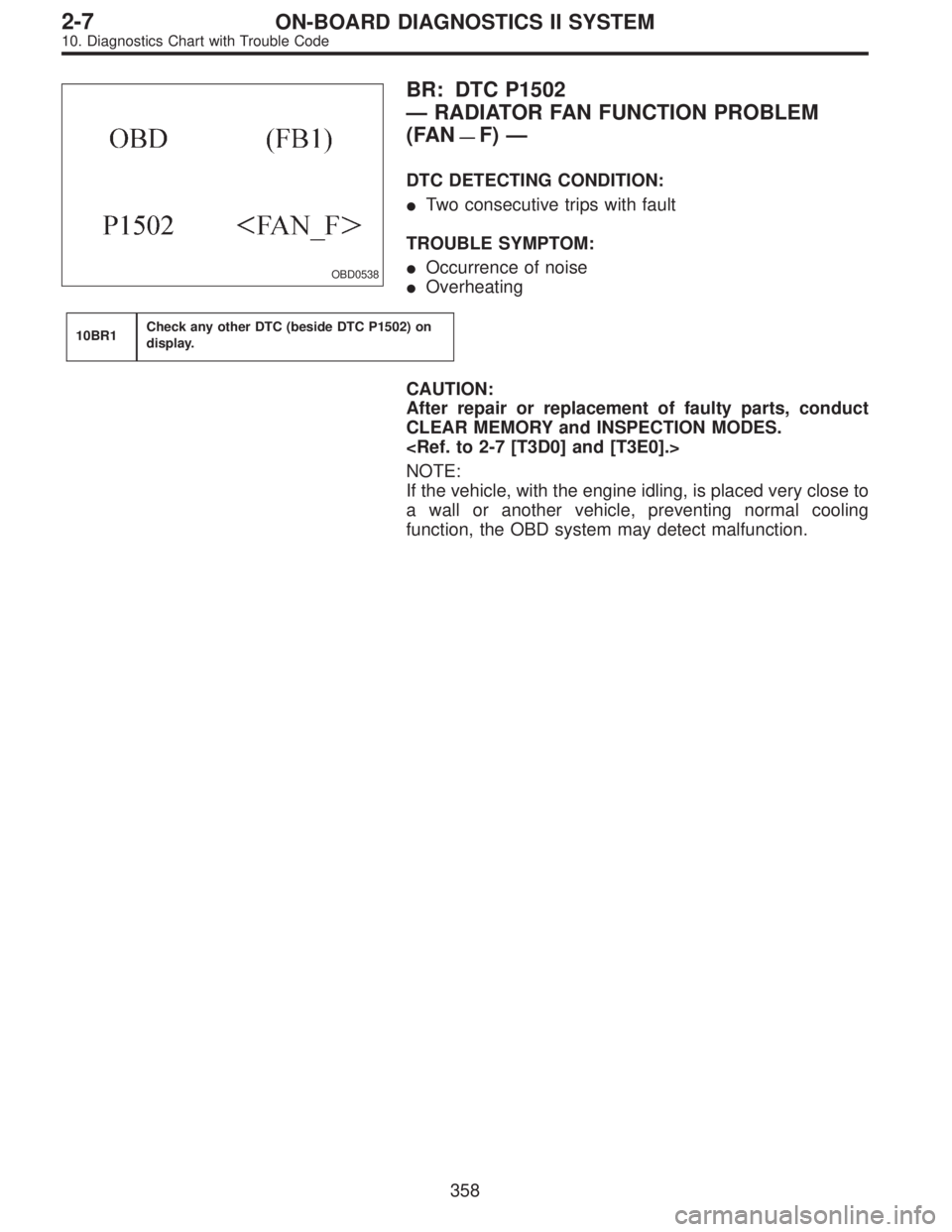
OBD0538
BR: DTC P1502
—RADIATOR FAN FUNCTION PROBLEM
(FAN
—F)—
DTC DETECTING CONDITION:
�Two consecutive trips with fault
TROUBLE SYMPTOM:
�Occurrence of noise
�Overheating
10BR1Check any other DTC (beside DTC P1502) on
display.
CAUTION:
After repair or replacement of faulty parts, conduct
CLEAR MEMORY and INSPECTION MODES.
NOTE:
If the vehicle, with the engine idling, is placed very close to
a wall or another vehicle, preventing normal cooling
function, the OBD system may detect malfunction.
358
2-7ON-BOARD DIAGNOSTICS II SYSTEM
10. Diagnostics Chart with Trouble Code
Page 2741 of 2890
 When working under a vehicle which is jacked-up,
always be sure to use safety stands.
2) The parking brake m")
3. Working Precautions
1. PRECAUTIONS WHEN WORKING WITH THE
PARTS MOUNTED ON THE VEHICLE
1) When working under a vehicle which is jacked-up,
always be sure to use safety stands.
2) The parking brake must always be applied during work-
ing. Also, in automatic transmission vehicles, keep the
select lever set to the P (Parking) range.
3) Be sure the workshop is properly ventilated when run-
ning the engine. Further, be careful not to touch the belt or
fan while the engine is operating.
4) Be careful not to touch hot metal parts, especially the
radiator and exhaust system immediately after the engine
has been shut off.
2. PRECAUTIONS IN TROUBLE DIAGNOSIS AND
REPAIR OF ELECTRIC PARTS
1) The battery cable must be disconnected from the bat-
tery’s (�) terminal, and the ignition switch must be set to the
OFF position, unless otherwise required by the diagnos-
tics.
2) Securely fasten the wiring harness with clamps and
slips so that the harness does not interfere with the body
end parts or edges and bolts or screws.
3) When installing parts, be careful not to catch them on
the wiring harness.
G6M0212
4) When disconnecting a connector, do not pull the wires,
but pull while holding the connector body.
11
6-3WIRING DIAGRAM
3. Working Precautions
![SUBARU LEGACY 1996 Service Repair Manual OBD0145A
CONFIRMATION OF ACTUAL DRIVING
PATTERN.
1) Conduct CLEAR MEMORY and INSPECTION MODES.
<Ref. to 2-7 [T3D0] and [T3E0].>
2) Connect Subaru select monitor to its data link connec-
tor.
3) Start](/manual-img/17/57433/w960_57433-1993.png "SUBARU LEGACY 1996 Service Repair Manual OBD0145A
CONFIRMATION OF ACTUAL DRIVING
PATTERN.
1) Conduct CLEAR MEMORY and INSPECTION MODES.
<Ref. to 2-7 [T3D0] and [T3E0].>
2) Connect Subaru select monitor to its data link connec-
tor.
3) Start")
 Turn ignition switch to OFF.
2) Remove main fan relay 1 and sub fan relay 1. (with A/C
models)
Remove main fan relay. (wit")