Page 1415 of 2890
![SUBARU LEGACY 1996 Service Repair Manual B4M0103
B4M0764
16. Flexible Hose
A: REMOVAL AND INSTALLATION
1) Disconnect battery negative terminal.
2) Discharge refrigerant using refrigerant recovery system.
<Ref. to 4-7 [W601].>
3) Remove low-p](/manual-img/17/57433/w960_57433-1414.png "SUBARU LEGACY 1996 Service Repair Manual B4M0103
B4M0764
16. Flexible Hose
A: REMOVAL AND INSTALLATION
1) Disconnect battery negative terminal.
2) Discharge refrigerant using refrigerant recovery system.
<Ref. to 4-7 [W601].>
3) Remove low-p")
B4M0103
B4M0764
16. Flexible Hose
A: REMOVAL AND INSTALLATION
1) Disconnect battery negative terminal.
2) Discharge refrigerant using refrigerant recovery system.
3) Remove low-pressure hose.
(1) Remove hose attaching bolts.
CAUTION:
Plug the opening to prevent foreign matter from get-
ting in.
(2) Disconnect the connector at evaporator module.
4) Remove high-pressure hose.
(1) Disconnect hose attaching bolt (compressor side).
(2) Disconnect hose attaching bolt (condenser side).
CAUTION:
Plug the opening to prevent foreign matter from get-
ting in.
5) Installation is in the reverse order of removal.
6) Charge refrigerant.
G4M0649
17. Relay and Fuse
A: LOCATION
Relays used with A/C system are located as shown in fig-
ure.
1) A/C relay
2) Main fan (radiator fan) relay
3) Sub fan (condenser fan) relay
4) Sub fan (condenser fan) water temperature relay
5) Fuses (10 A and 20 A)
G4M0651
B: INSPECTION
1) Check conduction with a circuit tester (ohm range)
according to the following table in figure.
B4M0105A
2) Replace relays which do not meet specifications.
39
4-7SERVICE PROCEDURE
16. Flexible Hose - 17. Relay and Fuse
Page 1416 of 2890
![SUBARU LEGACY 1996 Service Repair Manual B4M0103
B4M0764
16. Flexible Hose
A: REMOVAL AND INSTALLATION
1) Disconnect battery negative terminal.
2) Discharge refrigerant using refrigerant recovery system.
<Ref. to 4-7 [W601].>
3) Remove low-p](/manual-img/17/57433/w960_57433-1415.png "SUBARU LEGACY 1996 Service Repair Manual B4M0103
B4M0764
16. Flexible Hose
A: REMOVAL AND INSTALLATION
1) Disconnect battery negative terminal.
2) Discharge refrigerant using refrigerant recovery system.
<Ref. to 4-7 [W601].>
3) Remove low-p")
B4M0103
B4M0764
16. Flexible Hose
A: REMOVAL AND INSTALLATION
1) Disconnect battery negative terminal.
2) Discharge refrigerant using refrigerant recovery system.
3) Remove low-pressure hose.
(1) Remove hose attaching bolts.
CAUTION:
Plug the opening to prevent foreign matter from get-
ting in.
(2) Disconnect the connector at evaporator module.
4) Remove high-pressure hose.
(1) Disconnect hose attaching bolt (compressor side).
(2) Disconnect hose attaching bolt (condenser side).
CAUTION:
Plug the opening to prevent foreign matter from get-
ting in.
5) Installation is in the reverse order of removal.
6) Charge refrigerant.
G4M0649
17. Relay and Fuse
A: LOCATION
Relays used with A/C system are located as shown in fig-
ure.
1) A/C relay
2) Main fan (radiator fan) relay
3) Sub fan (condenser fan) relay
4) Sub fan (condenser fan) water temperature relay
5) Fuses (10 A and 20 A)
G4M0651
B: INSPECTION
1) Check conduction with a circuit tester (ohm range)
according to the following table in figure.
B4M0105A
2) Replace relays which do not meet specifications.
39
4-7SERVICE PROCEDURE
16. Flexible Hose - 17. Relay and Fuse
Page 1426 of 2890
6. Radiator Fan (Main Fan) Diagnosis
EPA0048
49
4-7DIAGNOSTICS
6. Radiator Fan (Main Fan) Diagnosis
Page 1431 of 2890
 dia.
�
1Hood hinge front attaching hole M8
�
2Strut mount attaching hole (Front center) 9.5 mm (0.374 in)
dia")
1. ENGINE COMPARTMENT AND ROOM
B5M0187A
�0Cowl panel weather attaching hole 6 mm (0.24 in) dia.
�
1Hood hinge front attaching hole M8
�
2Strut mount attaching hole (Front center) 9.5 mm (0.374 in)
dia.
�
3Front fender attaching hole (Tip) M6
�
4Rear upper surface of front side frame 12 mm (0.47 in) dia.
�
5Middle upper surface of front side frame 20 mm (0.79 in) dia.
�
6Front side frame front upper surface 14 x 16 mm (0.55 x 0.63
in) dia. oblong hole
�
7Side frame of front side frame 12 mm (0.47 in) dia.
�
8Headlight attaching hole at radiator side panel 6.2x9mm
(0.244 x 0.35 in) dia.
�
9Radiator panel side (LWR) gauge hole 23 mm (0.91 in) dia.
�
23Rear strut mount attaching hole (Side) 10 mm (0.39 in) dia.
�
24Rear strut mount attaching hole (Center) 12 mm (0.47 in) dia.
�
25Radiator panel (UPR) middle hole 6 mm (0.24 in) dia.
�
26Front fender attaching hole at radiator panel side M6
�
27Front fender attaching hole at front pillar lower portion M6
�
28Hinge middle hole at front pillar center 10 mm (0.39 in) dia.
�
29Front fender attaching hole at front pillar center portion M6
�
30Retainer attaching square hole at front pillar7x7mm(0.28
x 0.28 in)�
31Retainer attaching hole at center pillar (Front) 3.5 mm (0.138
in) dia.
�
32Retainer attaching hole at center pillar (Rear) 3.5 mm (0.138
in) dia.
�
33Lower side of rear door hinge M8
�
34Center pillar (LWR) gauge hole 27 mm (1.06 in) dia.
�
35Rear quarter outer corner patch attaching hole 5.2 mm (0.205
in) dia.
�
39Front rail center notch
�
40Front glass upper locating notch RH: 6.5 mm (0.256 in) dia.,
LH: 6.5 x 10 mm (0.256 x 0.39 in) dia. oblong hole
�
41Stud bolt lower locating notch
�
48Front center of rear floor pan 8 mm (0.31 in) dia.
�
51Front upper pillar (Inner) 7 mm (0.28 in) dia.
�
52Front seat belt adjust plate attaching hole 12 mm (0.47 in)
dia.
�
53Rear door hinge middle hole 10 mm (0.39 in) dia.
�
54Rear floor, near door 8 mm (0.31 in) dia.
�
55Trim upper attaching hole at 6 light 8 mm (0.31 in) dia.
�
56Trim lower attaching hole at 6 light 8 mm (0.31 in) dia.
�
58Rear floor, near floor strut 15 x 20 mm (0.59 x 0.79 in) dia.
oblong hole
3
5-1SERVICE DATA
2. Body Datum Points
Page 1434 of 2890
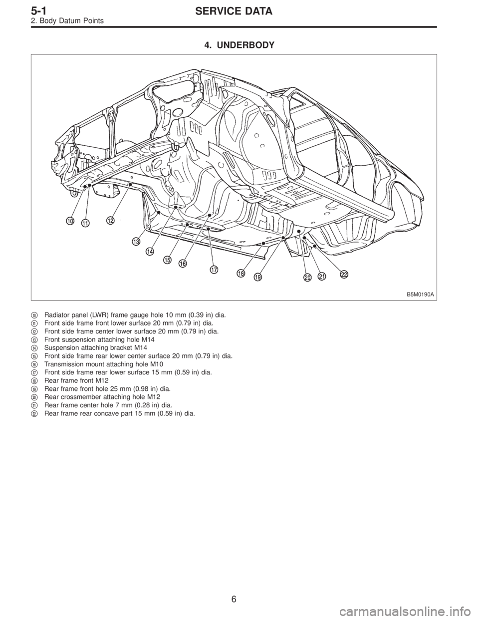
4. UNDERBODY
B5M0190A
�10Radiator panel (LWR) frame gauge hole 10 mm (0.39 in) dia.
�
11Front side frame front lower surface 20 mm (0.79 in) dia.
�
12Front side frame center lower surface 20 mm (0.79 in) dia.
�
13Front suspension attaching hole M14
�
14Suspension attaching bracket M14
�
15Front side frame rear lower center surface 20 mm (0.79 in) dia.
�
16Transmission mount attaching hole M10
�
17Front side frame rear lower surface 15 mm (0.59 in) dia.
�
18Rear frame front M12
�
19Rear frame front hole 25 mm (0.98 in) dia.
�
20Rear crossmember attaching hole M12
�
21Rear frame center hole 7 mm (0.28 in) dia.
�
22Rear frame rear concave part 15 mm (0.59 in) dia.
6
5-1SERVICE DATA
2. Body Datum Points
Page 1462 of 2890

1. Hood
The hood lock has a dual locking design which consists of
a main lock and a safety lock mechanism. When the
release knob located at the front pillar on the driver’s side
is pulled back, the main lock is released through the cable
attached to the knob.
The safety lock can be released by pushing the lever pro-
truding above the front grill while opening the hood.
G5M0137
A: REMOVAL
1. HOOD
1) Open front hood, and remove washer hose.
2) Remove attaching bolts.
3) Detach front hood from hinges.
B5M0267
2. HOOD LOCK
1) Open front hood and remove front grille.
2) Remove bolts which secure lock assembly to radiator
panel, and remove lock assembly.
3) Disconnect release cable from lock assembly.
B5M0319
3. RELEASE CABLE
1) Remove front grille.
2) Remove release cable from opener lever in passenger
compartment.
3) Remove release cable from lock assembly.
4) Remove cable clip from engine compartment.
G5M0140
B: POINTS TO CHECK
1) Check striker for bending or abnormal wear.
2) Check safety lever for improper movement.
3) Check other levers and spring for rust formation and
unsmooth movement.
33
5-1SERVICE PROCEDURE
1. Hood
Page 1463 of 2890
 beyond
radiator panel, make sure that:
�No clearance exists between buffe")
G5M0141
C: INSTALLATION
Installation is in the reverse order of removal.
CAUTION:
With buffer protruding about 18 mm (0.71 in) beyond
radiator panel, make sure that:
�No clearance exists between buffer and inner hood.
�Hood main lock is applied when hood is released at
a height of approximately 10 cm (3.94 in) above the
closed position.
G5M0142
NOTE:
�Align the center of striker with lock during installation.
Make sure safety lever is properly caught by striker under
the hood’s own weight.
�Route hood lock release cable and hold with clips.
�After installing release cable, ensure it operates
smoothly.
�Apply grease to sliding surfaces of parts.
B5M0268A
D: ADJUSTMENT
1) Fore-aft and left-right adjustments
Loosen striker mounting bolts and adjust fore-and-aft posi-
tion of striker.
CAUTION:
Do not adjust striker position using the lock. Doing so
may result in a misaligned front grille.
2) Up-down adjustment
Make up-and-down adjustment of striker only when hood
does not properly contact buffer or hood is not flush with
fender, or when release cable does not properly operate.
Adjustment can be made by adjusting the stroke length of
striker after lock assembly mounting screws are removed.
34
5-1SERVICE PROCEDURE
1. Hood
Page 1773 of 2890

�
2Ignition coil
�
3Ignitor
�
4Crankshaft position sensor
�
5Camshaft position sensor
�
6Throttle position sensor
�
7Fuel injectors
�
8Pressure regulator
�
9Engine coolan")
�1Engine control module (ECM)
�
2Ignition coil
�
3Ignitor
�
4Crankshaft position sensor
�
5Camshaft position sensor
�
6Throttle position sensor
�
7Fuel injectors
�
8Pressure regulator
�
9Engine coolant temperature sensor
�
10Mass air flow sensor
�
11Idle air control solenoid valve
�
12Purge control solenoid valve
�
13Fuel pump
�
14PCV valve
�
15Air cleaner
�
16Canister
�
17Main relay
�
18Fuel pump relay
�
19Fuel filter
�
20Front catalytic converter
�
21Rear catalytic converter
�
22EGR valve (AT vehicles only)
�
23EGR control solenoid valve (AT vehicles only)
�
24Radiator fan�
25Radiator fan relay
�
26Pressure sources switching solenoid valve
�
27Knock sensor
�
28Back-pressure transducer (AT vehicles only)
�
29Front oxygen sensor
�
30Rear oxygen sensor (Except 2200 cc California model)
�
31Pressure sensor
�
32A/C compressor
�
33Inhibitor switch
�
34CHECK ENGINE malfunction indicator lamp (MIL)
�
35Tachometer
�
36A/C relay
�
37A/C control module
�
38Ignition switch
�
39Transmission control module (TCM) (AT vehicles only)
�
40ABS/TCS control module (TCS equipped models)
�
41Vehicle speed sensor
�
42Data link connector (For Subaru select monitor)
�
43Data link connector (For Subaru select monitor and OBD-II
general scan tool)
�
44Two way valve
�
45Rear oxygen sensor (2200 cc California model only)
�
46Filter
5
2-7ON-BOARD DIAGNOSTICS II SYSTEM
1. General
 Diagnosis
EPA0048
49
4-7DIAGNOSTICS
6. Radiator Fan (Main Fan) Diagnosis")