Page 802 of 2189

Transmission
Removal(cont'd)
'10. Remove the cotter pins and castle nuts, th€n separatethe balljoints from the lower arms (see section 1gl.
DAMPER PINCH BOLT
NUT
FORI(FORK BOLT
11. Remove the right damper fork bolt. th€nright damper fork and dampor.
COTTER PINReplace.
separate
12.
1a
14.
Pry the right and left driveshafts out ofthe differential.
Pull on the inboard joint to remove the right and leftdrivsshafts (see section 16).
Tie plastic bags over the driveshaft onds.
NOTE: Coat all precision finished surfaces with cleanengine oil.
Remove the exhaust pipe A,
NOTE: Dl6YB engine is shown; D16y7 engine issimilar.
t9.
SELF-LOCKING NUTReplace.
L
14-124
EXHAUST PIPE AMOUNT/BRACKET
17.
18.
16. Remove the shift cable cover. then remove the shiftcable by removing the control lever,
CAUTION: Take car6 not to bond the shift cable.
Remove the right front mounvbracket.
Remove the ATF cooler hoses at the ATF coolerlines. Tufn the ends of the ATF cooler hoses uo toprevent ATF from flowing out, then plug the ATFcooler hosgs and lines.
NOTE: Check for any sign of leakage at the hoseioints.
WASHER
Page 803 of 2189
19. Remove the engine stiffener and the torque con-
verter cover.
Remove the eight drive plate bolts one at a tlme
while rotating the crankshaft pulley.
Remove the distributor.
Attach a hoisting bracket to the engine, then lift the
engine slightly.
HOISTBRACKET
20.
21.
COVER
23. Place a jack under the transmission. and ra6a :'.
transmission iust enough to take weight otf ol tF.
mounts. then remove the transmission mounl
TRANSMISSIONMOUNT BRACKET
Remove the transmission housing mounting bolts
and the rear engine mounting bolts.
Pull the transmission away from the engine until it
clears the 14 mm dowel pins, then lower it on the
transmission jack.
TRANSMISSION HOUSING
lf necessary, remove the torque converter anc:"
starter motor.
24.
25.
1+16
Page 809 of 2189

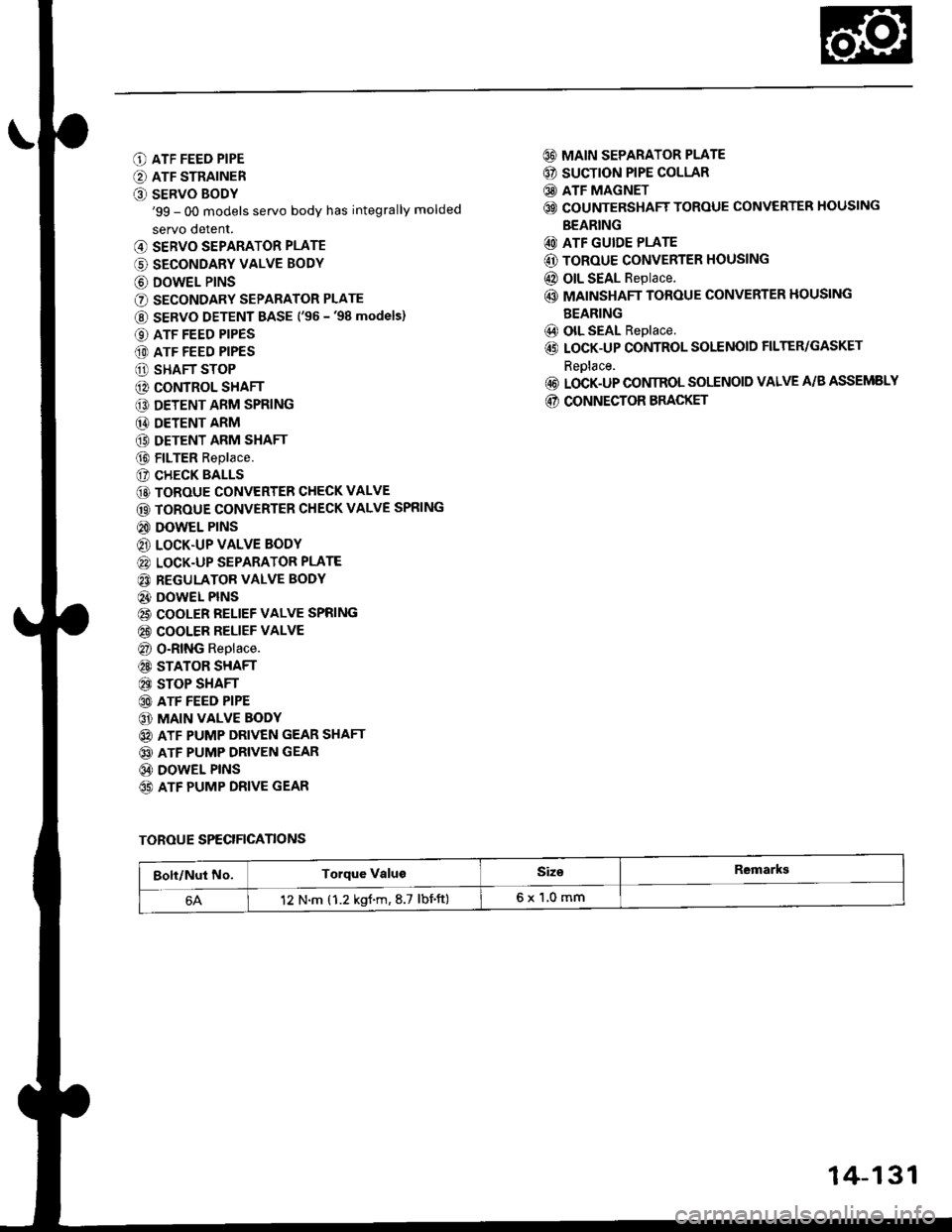
O ATF FEED PIPE
O ATF STRAINER
O SERVO BODY'99 - 00 models servo body has integrally molded
servo detent.
@ SERVO SEPARATOR PLATE
(' SECONDARY VALVE BODY
@ DOWEL P|NS
O SECONDARY SEPARATOR PLATE
@ SERVO DETENT BASE ('�96 -'98 models)
O ATF FEED PIPES
(D ATF FEED PIPES
O SHAFT STOP
@ CONTROL SHAFT
€D DETENT ARM SPRING
@ DETENT ARM
(9 DETENT ARM SHAFT
@ FILTER Replace.
(? CHECK BALLS
@ TOROUE CONVERTER CHECK VALVE
@ TOROUE CONVERTER CHECK VALVE SPRING
@ DOWEL PINS
@ LOCK.UP VALVE BODY
@ LOCK-UP SEPARATOR PLATE
@ REGULATOR VALVE BODY
@} DOWEL PINS
@ COOLER RELIEF VALVE SPRING
@ COOLER RELIEF VALVE
@ O-RING Replace.
@ STATOR SHAFT
@ STOP SHAFT
@ ATF FEED PIPE
@ MAIN VALVE BODY
@ ATF PUMP DRIVEN GEAR SHAFT
@ ATF PUMP DRIVEN GEAR
@ DOWEL PINS
65) ATF PUMP DRIVE GEAR
@ MAIN SEPARATOR PLATE
@ SUCTION PIPE COLLAR
@ ATF MAGNET
@ COUNTERSHAFT TOROUE CONVERTER HOUSING
BEARING
@ ATF GUIDE PLATE
@ ToRoUE CONVERTER HOUSING
@ OIL SEAL Replace.
@ MAINSHAFT TOROUE CONVERTER HOUSING
BEARING
@) olL SEAL Replace.
@ LOCK-UP CONTROL SOLENOID FILTER/GASKET
Reolace.
@ LOCK-UP CONIROL SOLENOID VALVE A/B ASSEMELY
@ CONNECTOR BRACKET
TOROUE SPECIFICANONS
Bolt/Nut No.Torque ValugSiz€Remarkg
12 N.m (1.2 kgf.m,8.7 lbnft)6x1,0mm
14-131
Page 814 of 2189
Torque Converter Housing/Valve Body
Removal
ATF FEEO PIP€
LOCK-UP VALVEBODY
PIN
6x1.0mm
LOCK-UP SEPARATORPLATE
REGULATORVALVE SODY
DOWEL PIN
COOLER RELIEF VAL
SERVO DETENTSTRAINER
SERVO EODY
SEPARATON
BASE
ATF FEEDPIPES
CONTROLSHAFT
DETENTARM SHAFT
DETENTARM
ATF FEED PIPE
6x1.0mm5 Eolts6x1.0mm3 Eolts
MAIN VALBODY
ATF PUMP
DRIVEN
VALVE BODY
PINGEAR SHAFT
ATF PUMP
MAIN SEPARAPLATE
SECONDARYSEPARATOR PLATE
NOTE: The illustration shows the '96 - 98 models, the '99 - 00 models do not have the servo detent base; the servo detentis integral with the servo body.
L
14-136
Page 815 of 2189

NOTE;
. Clean all parts thoroughly in solvent or carburetor
cleaner, and dry with compressed air.
. Blow out all passages.
. When removing the valve body, replace the O-ring.
l, Remove the ATF feed pipes from the servo body,
secondary valve body and main valve body.
For'96 - 98 models: Remove the ATF strainer and
servo detent base (two bolts).
For'99 - 00 models: Remove the ATF strainer (one
bolt).
Remove the servo body and servo separator plate
{'96 - 98 models: seven bolts,'99 - 00 models: eight
bolts).
Remove the secondary valve body, shaft stop and
secondary separator plate (three bolts).
Remove the lock-up valve body and separator plate
{seven bolts).
Remove the regulator valve body (one boltl.
Remove the stator shaft and stop shaft.
Remove the detent spring from the detent arm. then
remove the control shaft from the to.que converter
housing.
Remove the detent arm and detent arm shaft from
the main valve body.
Remove the main valve body (five bolts).
NOTE: Do not let the eight check balls fall outofthe
main valve body when removing the main valve
body.
Remove the ATF pump driven gear shaft, then remove
the ATF pump gears.
Remove the main separator plate and two dowel
pins.
7.
't'1.
10.
12.
14.
13. CIean the inlet opening of the ATF strainer thor-
oughly with compressed air. then check that it is in
good condition, and the inlet opening is not clogged.
INLET OPENING
Test the filter by pouring clean ATF fluid through
the inlet opening. Beplace the ATF strainer if it is
clogged or damaged.
NOTE: The ATF str8iner can be reused if it is not
clogged.
14-137
Page 819 of 2189
ATF Pump
Inspection
1. Install the ATF pump gears and ATF pump driven
gear shaft in the main valve body
NOTE:
. Lubricate all parts with ATF during inspection.
. Install the ATF pump driven gear with its grooved
and chamfered side facing up as shown.
MAIN VALVE BODY
ATF PUMP ORIVEN GEAR
Grooved and chamfe.ed side
2. Measure the side clearance of the ATF pump drave
and driven gears.
ATF Pump Gears Side {Radial) Clearance:
Standard (New):
ATF Pump Drive Gear
0.105 - 0.1325 mm {0.004 - 0.q)5 in}
ATF Pump Drivsn Gear
0.035 - 0.0625 mm (0.0014 - 0.0025 inl
MAIN VALVE SOOY
YZ]
o?
ATF PUMPDRIVE GEAR
ATF PUMPDRIVEN GEARInspect teeth for wear and damage
lnspect teeth for wear and damage.
3. Remove the ATF pump driven gear shaft. Measure
the thrust clearance of the ATF pump driven gear-
to-valve bodY.
ATF Pump Drive/Drivon Gear Thrust {Axial} Cloarance:
Standard (Now): 0.03 - 0.05 mm 10'001 - 0.002 inl
Sorvice Limit: 0.07 mm (0.003 in)
1+141
Page 833 of 2189
One-way Clutch
Disassembly/lnspection/Reassembly
1. Separate countershaft 1st gear from the park gear
by turning the park gear in the direction shown
2. Remove the one-way clutch by prying it up with the
end of a screwdriver.
COUNTERSHAFT 1ST GEARONE-WAY CLUTCHNOTE: lnstall in this direction.
ONE'WAY CLUTCH
COUNTERSHAFT lST GEAR
COUNTERSHAFT lST GEAR
SCREWORIVER
14-155
3. Inspect the parts as followsl
PARK GEARInspecl the park gear
for wear and scorrng.
ONE-WAY CLUTCHInspect the one-way
clutch for damage and
laulty movement.
lST GEABInspect countershalt lst gear
for wear ancl scorlng.
After the parts are assembled, hold countershaft 1st
gear and turn the park gear in the direction shown
to be sure it turns freely. Also make sure the park
gear does not turn in the opposite direction.
Page 846 of 2189

Differential
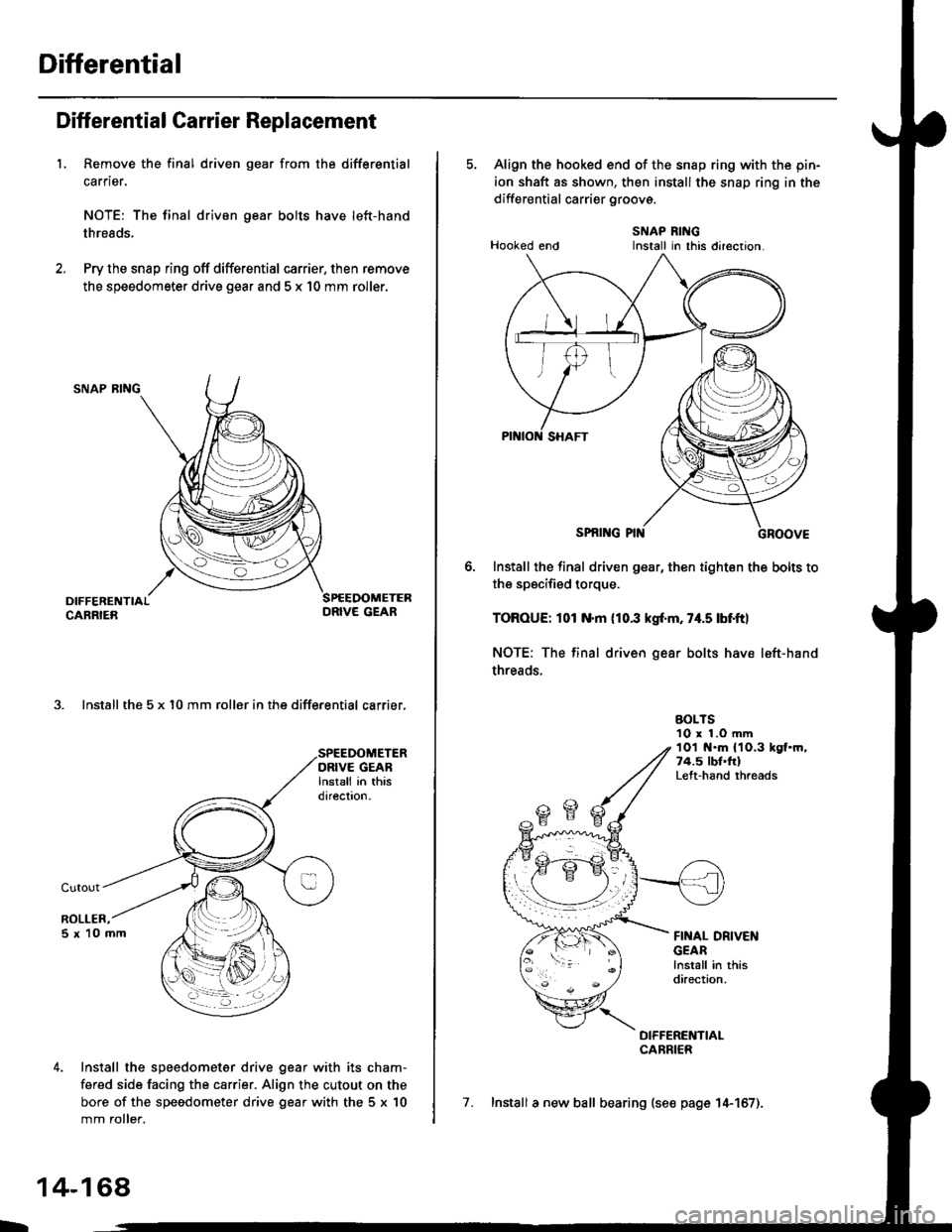
Diff erential Carrier Replacement
L Remove the final driven gear from the differential
carrier.
NOTE: The final driven gear bolts have left-hand
threads.
Pry the snap ring off differential carrier, then remove
the speedometer drive gear and 5 x 10 mm roller.
SNAP RING
3. Install the 5 x l0 mm roller in the differential carrier,
Install the speedometer drive gear with its cham-
fered side facing the carrier. Align the cutout on the
bore of the speedometer drive gear with the 5 x 10
mm roller.
L
14-168,
5. Align the hooked end of the snap ring with the pin-
ion shaft as shown, then install the snap ring in the
differential carrier groovs.
SNAP RINGHooked end Install in this direction.
SPNI G PIN
Install the final driven gear, then tighten the bolts to
the specified torque.
TOROUE: 101 N.m (10.3 kgf'm, 74.5 lbf.ftl
NOTE: The final driven gear bolts have left-hand
threads.
BOLTS10 r 1.O mm1Ol t{.m 11O.3 kgf.m,74.5 lbl.frlLeft-hand rhreads
FINAL DRIVENGEARlnstall in thisdirection.
DIFFERENTIALCARRIER
7. Install a new ball bearing (se€ page 14-157).
Install in this direclon.