Page 892 of 2189
Description
Hydraulic Flow (cont'dl
lll position, at low spo€d range
The flow of fluid up to the drive pulley, the driven pulley, and the clutch reducing valve is the same as in El position. Thepulley ratio is low because the driven pulley receives high pressure (PH), and the drive pulley receives low pressure (pL),The clutch reducing pressure {cR) flows through the manual valve to the forwaro clutch, ttren forward ciulcn is engaged.The forward clutch then drives the drive pulley shaft, which drives the d(ven pu ey shaft.Also' clutch reducing pressure {cR) flows to the start clutch control valve, and becomes clutch control pressure {cc).clutch control pressure (cc) becomes start clutch pressure (sc) at the shift inhibitor valve. stan clutch pressure {sc) isapplied to the start clutch to engage the start clutch.
14-214
Page 901 of 2189
Component Locations
36 - 98 Models
BRAKE SWITCH
DRIVEN PULLEYSPEED SENSOR
INHIBITOR SOLENOID
ENGINE CONTROLMODULE IECMI
SECONDARY GEAR SHAFTSPEEO SENSOR
AUTOMATIC TRANSAXLE (A/T}GEAR POSITION SWITCI{
MANIFOLD ABSOLUTE
VEHICLE SPEEO SENSOR{vss}
IMAPI SENSOR
THROTTI.I POSITION {TPISENSOR
PH.PL CONTROLLINEAR SOLENOID
/i/ i,' / ,','4
,i/:1
t"--.---.- i,,
-_,-:-_a.--:
il
START CLUTCH CONTROLLINEAR SOLENOIDPULLEY
SHIFT CONTROLLINEAR SOLENOTD
$r,
14-224
h
SPEED SENSOR
Page 906 of 2189

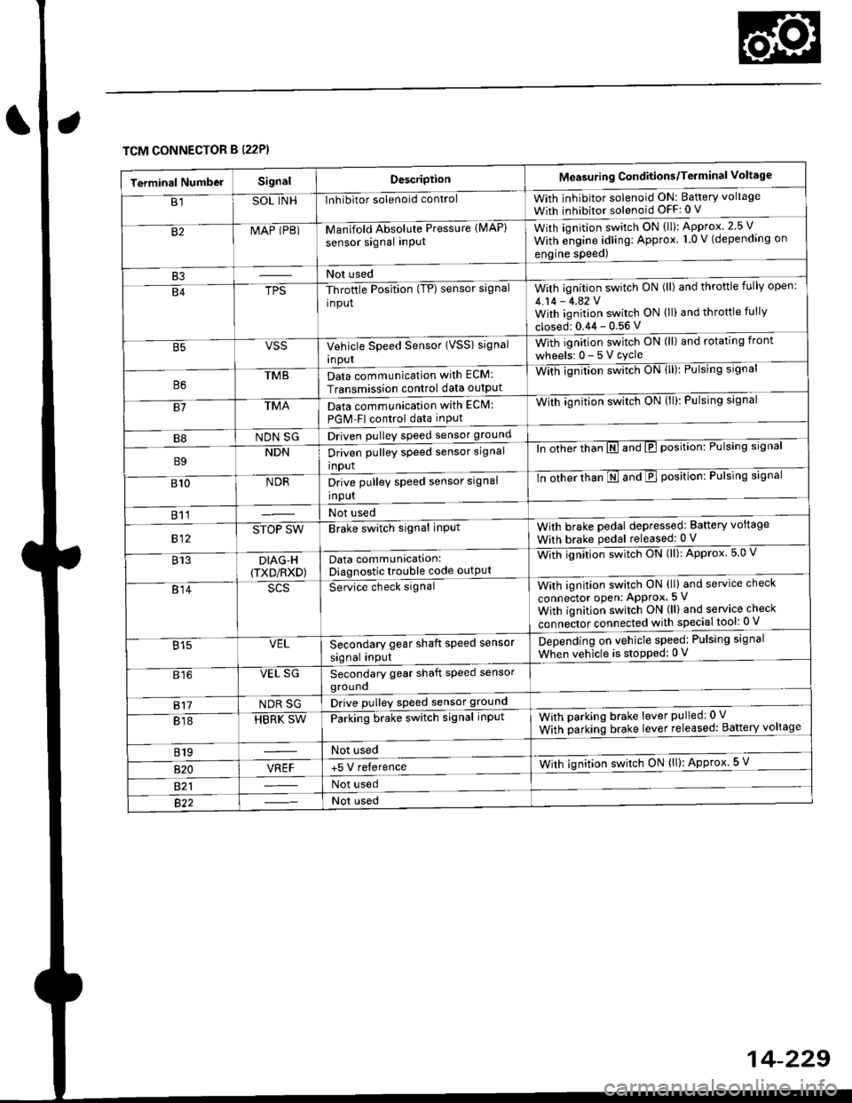
TCM CONNECTOR B (22P}
Terminal NumbelSignalDescriptionMeasuring Conditions/Terminal Voltage
B1SOL INHInhibitor solenoid controlWith inhibitor solenoid ON: Baftery voltage
With inhibitor solenoid OFF: 0 V
82MAP (PB)-M an if old Absol r-rte Pressure IMAP)
sensor signal inPUtWith iqnition switch ON (ll): Approx.2.5 V
With e;gine adling: Approx. 1.0 V (depending on
engine speed)
B3Not used
B4TPS-Throttle Position (TP) sensor signal
input
With ignition switch ON (ll) and throftle fully open:
4.14 - 4.42 VWith ignition switch ON (ll) and throttle fully
closed: 0.44 - 0.56 V
VSSVehicle Speed Sensor (VSS) signal
Inpur
With ignition switch ON (ll) and rotating front
wheelsr 0-5Vcycle
TMBData communication with ECM:
Transmission control data outpUt
With ignilion swltch UN lll): rulslng slgnar
81TMAData communication with EClvl:
PGM Fl control data inPut
With ignition swltch uN {ll,: l-ulslng slgnal
B8NDN SGDriven pulley speed sensor ground
B9NDNDriven pulley speed sensor signal
input
ln other thTnE and E position: Pulsing signal
810NDRDrive pulley speed sensor signal
Input
-tn ottrer ttran E ana E position: Pulsing signal
811Not used
812STOP SWBrake switch signal inPutWith brake pedal depressed: Battery voltage
With brake pedal released: 0 V
813DIAG-H(TXD/RXD)Data communication:Diagnostic trouble code outPut
Wittr ignitio.r s*itct' ON (ll): Approx 5.0 V
814Se-ice ctrect signatWith ignition switch ON (ll) and service check
connector oPen: APProx.5 V
With iqnition switch ON (ll) and service check
"onn"itot. connect"d with special tool: 0 V
Secondary gear shaft speed sensor
signal input
Depending on vehicle speed: Pulsing signal
When vehicle is stoPped: 0 V815VEL
816VEL SGSecondary gear shaft speed sensorgrouno
817NDR SGDrive pulley speed sensor ground
818HBRK SWParking brake switch signal inPutWith parking brake lever pulledr 0 V
With parking brake lever released: Battery voltage
819Not used
B�20VREF+5 V relerenceWith ignition switch ON (ll): Approx 5 V
821Not used
Not used
Page 910 of 2189
![HONDA CIVIC 1996 6.G Workshop Manual \a
PCM CONNECTOR D {16P)
14-233
Terminal Numbs]SignalDescriptionMeasuring Conditions/Terminal Voltage
D1VELSecondary gear shaft speed
sensor signal input
Depending on vehicle speed: Pulsing signal
Whe HONDA CIVIC 1996 6.G Workshop Manual \a
PCM CONNECTOR D {16P)
14-233
Terminal Numbs]SignalDescriptionMeasuring Conditions/Terminal Voltage
D1VELSecondary gear shaft speed
sensor signal input
Depending on vehicle speed: Pulsing signal
Whe](/manual-img/13/6068/w960_6068-909.png)
\a
PCM CONNECTOR D {16P)
14-233
Terminal Numbs]SignalDescriptionMeasuring Conditions/Terminal Voltage
D1VELSecondary gear shaft speed
sensor signal input
Depending on vehicle speed: Pulsing signal
When vehicle is stoPPed: APProx. 0 V
02SOL INHlnhibitor solenoid controlWith inhibitor solenoid ON: Battery voltage
With inhibitor solenoid OFF: 0 V
D3SH LSMShift control linear solenoid
power supply negative electrode
D4SH LSPShift control linear solenoid
power supply positive electrode
With ignition switch ON (ll): Pulsing signal
D5VB SOLPower supply for solenoid valvesWith ignition switch ON (ll): Baftery voltage
With ignition switch OFF:0 V
D6ATP RA,/T gear position switch E
position input
InEposition:0V
In other than B position; Approx. 10 V
D]VEL SGSecondary gear shaft sPeed
sensor ground
D8Not used
D9Not used
D10NDNDriven pulley speed sensor signal
anput
In other than E and E position: Pulsing signal
D11NDRDriven pulley speed sensor signal
input
ln other than E and E position: Pulsing signal
D12NDR SGDrive pulley speed sensor ground
D13ATP SA,/T gear position switch E
position input
InE position: 0V
In other than E position: Battery voltage
D14D INDD indicator light controlWhen ignition switch is first turned ON (ll):
Battery voltage for two seconds
In E position: Battery voltage
D15Not used
D16NDN SGDriven pulley speed sensor
grou nd
Page 915 of 2189

Symptom-to-Component Chart
Electrical System -'96 - 98 Models
*: The DTC in parentheses is the code @ indicator light indicates when the Data Link Connector is connected to the HondaPGM Tester.
DTC*O Indicator
LightMILDetection ltemPage
P1790
(3)BlinksONThrottle position sensor14-242
P179'l
(4)BlinksONVehicle speed sensor14-243
P1705
(5)BlinksONAy'T gear position switch (short to groundl't 4-244
P1706
(6)OFFONA/T gear position switch {open)14-246
P0725
(11)BlinksONlgnition coil14-248
P1793
112lBlinksONManifold absolute pressure sensor14-249
P 1870(30)BlinksONShift control linear solenoid14-250
P'1873
(311BlinksONPH-PL control linear solenoid14-25'l
P1879(32)BlinksONStart clutch control linear sotenoid14-252
P1882BlinksONInhibitor solenoid14-253
P1885
(34)BlinksONDrive pulley speed sensor1l-Zb4
P1886(35)BlinksONDriven pulley speed sensor14-255
P1888
(36)BlinksONSecondary gear shaft speed sensor14-256
T to55
(37)BlinksONECM or TCM14-257
P1890
l42lBlinksONShift control system14-259
P1891
(43)BlinksONStart clutch control svstem14-260
14-23a
Page 917 of 2189
Symptom-to-Com ponent Chart
Electrical System -'99 - 00 Models
r: The DTc in parentheses is the code E indicator light indicates when the Data Link connector is connected to the HondaPGM Tester.
DTCTE Indicatot
LighrMILDetostion ltemPage
P1705
(5)ElinksONA,/T gear position switch (short to grouno,14-265
P1706
(6)OFFONA"/T gear position switch (open)14-26€
P1870
(30)BlinksONShift control linear solenoid14-271
P1873
(31)BlinksONPH-PL control linear solenoid14-213
P1879
t32lBlinksONStan clutch control linear solenoid
Inhibitor solenoid
14-215
P1882(33)BlinksON't 4-277
P1885
(34)BlinksONDrive pulley speed sensol't 4-279
P1886
(35)BlinksONDriven pulley speed sensor14-281
P1888
(36)BlinksONSecondary gear shaft speed sensor
Shift control system
14-283
P1890
\421BlinksON14-245
P1891
(43)BlinksONStart clutch control system14-286
14-240
Page 969 of 2189
Drive Pulley/Driven Pulley/Secondary Gear Shaft Speed
Sensors
Replacement
CAUTION: While replacing the speed sensor, be sure not to allow dust and other foreign parliclos to enter into the trans-mission.
'1. Disconnect the connectors for the drive pulley, the driven pulley, and the secondary gear shaft speed sensor.
2. Remove the 6 mm bolt from the transmission housing, and remove the drive pulley. the driven pulley, and the sec-ondary gear shaft speed sensors.
3. Replace the O-rings before reinstalling the drive pulley, the driven pulley, and the secondary gear shaft sp€ed sen-sors.
6x1.0mm12 N.m (1.2 kgf.m,8.7 lbf.ft)
6x1.0mm12 N.m (1.2 kgt.m,8.7 tbf.ft)
DRIVEN PULLEY SPEED SENSOB
14-292
Page 972 of 2189

t.
rl,
fl,
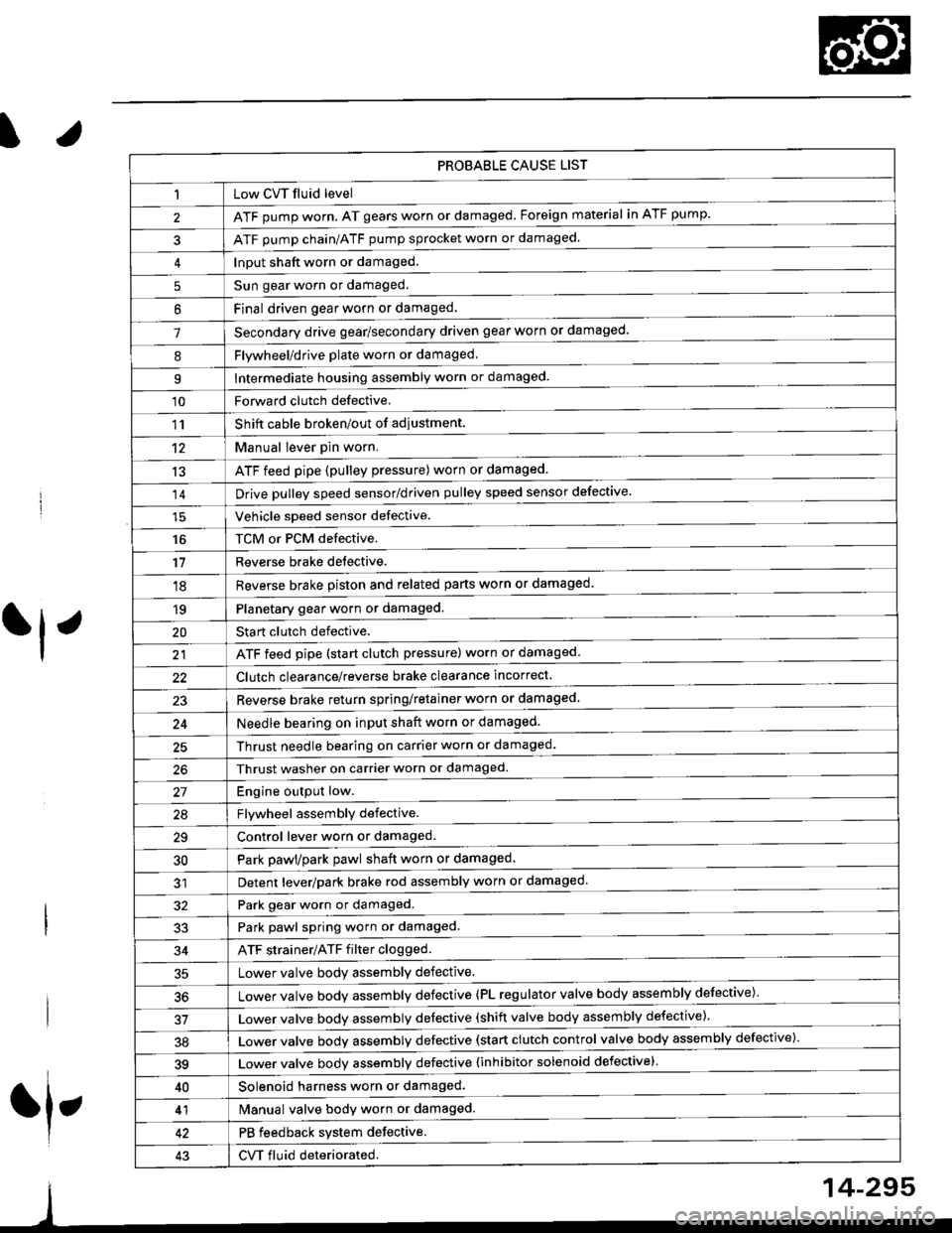
PROBABLE CAUSE LIST
Low CVT fluid level
ATF pump worn. AT gears worn or damaged. Foreign material in ATF pump.
ATF pump chain/ATF pump sprocket worn or damaged.
Input shaft worn or damaged.
Sun gear worn or damaged.
Final driven oear worn or damaqed,
Secondary drive gear/secondary driven gear worn or damaged-
5
6
1
8Flywheel/drive plate worn or damaged.
Intermediate housing assembly worn or damaged.9
'10Forward clutch defective.
Shift cable broken/out of adiustment.
M"nu"t t"uffi
ATF feed pipe (pulley pressure) worn or damaged.
Vchiclc speed sensor defective.
TCM or PCM defective.
Reverse brake detective.
1'�r
't2
13
14
16
'11
'18
1qPlanetary gear worn or damaged.
Sta rt clutch defective.
ATF feed pipe (start clutch pressure) worn or damaged
20
t't
Clutch clearance/reverse brake clearance incorrect.
23Reverse brake return spring/retainer worn or damaged
24Needle bearing on input shaft worn or damaged.
25Thrust needle bearing on carrier worn or damaged.
Thrust washer on carrier worn or damaged.
Enoine outout low.------------------------
Flvwhcel assemblv defective.
Control lever worn or damaged.
Park pawl/park pawl shaft worn or damaged
Detent lever/park brake rod assembly worn or damaged
27
29
30
32Park gear worn or damaged.
Park pawl spring worn or damaged.
ATF strainer/ATF filter clogged.
Lower valve body assembly defective.
Lower valve bodv assemblv defective (PL regulator valve body assembly defective)'
33
34
50
Lower valve bodv assembly defective (shift valve body assembly defective).
Lower valve bodv assemblv defective (start clutch control valve body assembly defective)'
39Lower valve bodv assemblv defective {inhibitor solenoid defective}
40Solenoid harness worn or damaged.
Manual valve body worn or damaged.
PB feedback system defective.
CVT fluid deteriorated.
41
43
14-295