1996 HONDA CIVIC indicator light name
[x] Cancel search: indicator light namePage 358 of 2189

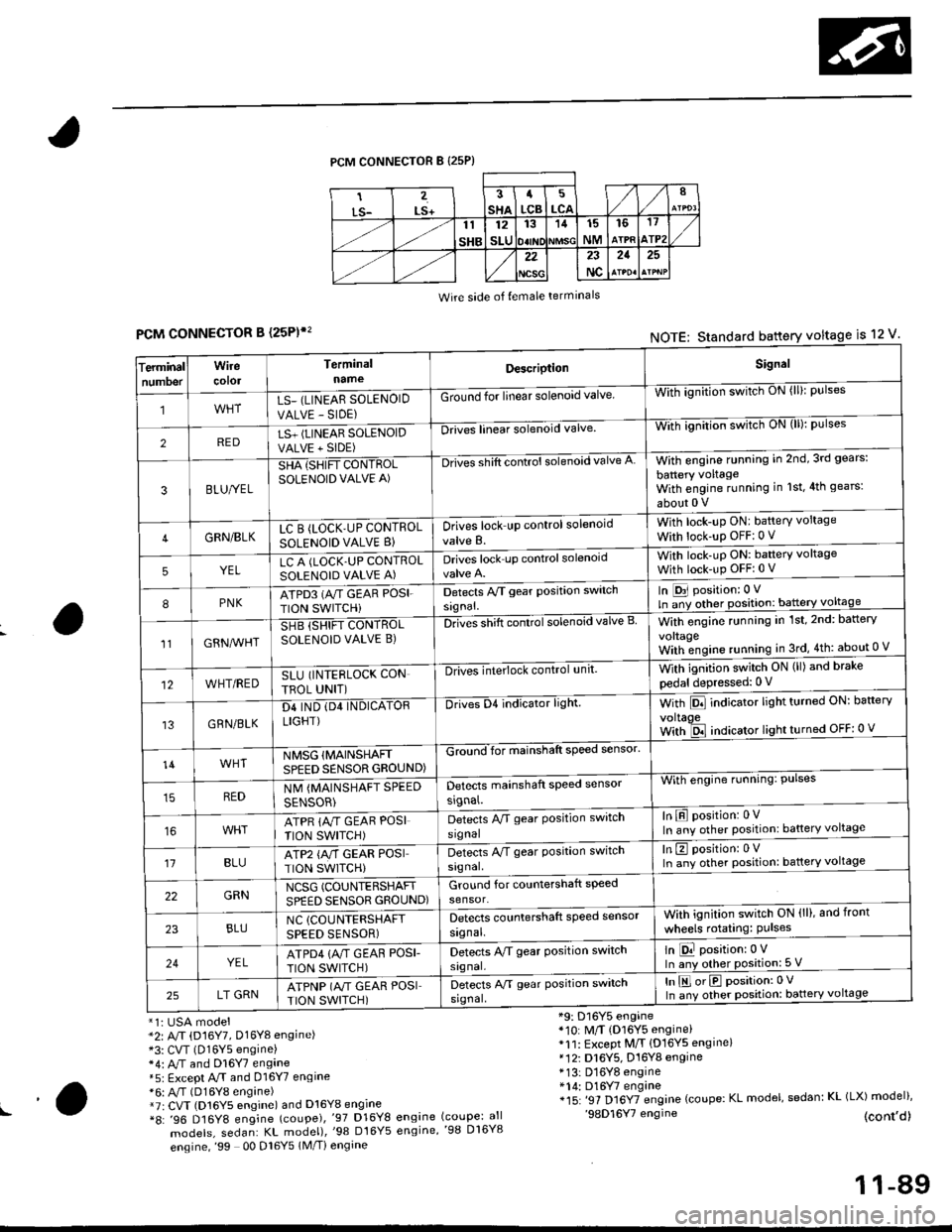
PCM CONNECTOR B {25P)
Wire side of {emale terminals
CONNECTOR B (25P)',
*1i USA model*2: A/T (D16Y7, Dl6Yg engine)*3: CVT (D16Y5 engine)*4: M and Dl6Y7 engane*5: Except A.rT and 016Y7 engine*6: A,/T (D16Y8 engine)*7r CVT (D16Y5 engine) and D16Y8 engine*8: '96 D16Y8 engine (coupe),'97 D16Y8
models, sedan: KL model),'98 Dt6Y5
engine,'99 00 Dl6Y5 1M/Ti engine
*9: D16Y5 engine*10: M/T (D16Y5 engine)*11: Except M/T {D16YS engine}*12i D16Y5, D16Y8 engine* 13: D16Y8 engine*14: D16Y7 engine*15: '97 Dl6YTengine (coupe: KL model, sedan: KL (LX) model)''98D16Y7 engine (cont,d)engine (coupe: allengine,'98 D16Y8
FCMNOTE: Standard battery voltage is 12 v'
erminalTnumoer
Wirecotol
TerminalnameDescriptionSignal
1LS_ (LINEAR SOLENOID
VALVE - SIDE)
Ground for linear solenoid valveWii-ignnion switctr oN {ll}: pulses
2REDLS+ (LINEAR SOLENOIDVALVE + SIDE)
-Drii6l linear solenoid valveWith ignilion switch uN (lll: pulses
3BLU/YEL
SHA {SHIFT CONTROLSOLENOID VALVE A)
-Drives shift control solenoid valve AWith engine running in 2nd,3rd gears:
battery voltageWith engine running in 1st,4th gears:
about 0 V
4GRN/BLKLC B (LOCK'UP CONTROL
SOLENOID VALVE B}Drives lock up control solenoid
valve B.
With lock-up ONI battery voltage
With lock-up OFF:0 v
5YELLC A (LOCK.UP CONTROLSOLENOID VALVE A)Drives lock up controlsolenoidWith lock-uP ON: baftery voltage
With lock-up OFFi 0 V
8PNKATPD3 (NT GEAR POSI.
TION SWITCHi
Detects Py'T gear Position switch
signal.
In [D31 position: 0 V
ln ;y other position: battery voltage
1lGRN^lr'HT
SHB (SHIFT CONTROLSOLENOID VALVE B)DnGs shift conttol solenoid valve BWith engine running in 1st,2nd: battery
vo|taqeWith;ngine running in 3rd,4th: about 0 V
12WHT/REDSLU (INTERLOCK CON
TBOL UNIT)
-DlivEilite'lock control,rnit.With ignition switch ON (ll) and brake
pedal depressed: 0 V
13GRN/BLK
D4 IND (D4 INDICATORLIGHT)
Drives D4 indicator light.With Pll indicator lrght turneo urr: oarterv
voltaoeWith ld indicator light turned OFF: 0 v
14WHTNMSG {MAINSHAFTSPEED SENSOR GROUND)
GZiiI'for mainshaft speed sensol
With engine running: Pulses
In E position: 0VIn any other position: battery voltage
REDNM {MAINSHAFT SPEED
SENSOR)
Detects mainshaft speed sensor
srgnal.
ATPR {M GEAR POSI
TION SWITCH)
Detects M gear Position switch
signal
't1BLUATP2 {A/T GEAR POSITION SWITCH)
Detects A/T gear Position switch
signal.
In E position: 0VIn any other position: battery voltage
22GRNNCSG (COUNTERSHAFT
SPEED SENSOR GROUND)Ground for countershaft speed
sensor.
23BLUNC (COUNTERSHAFT
SPEED SENSOR)
Detects countershaft speed sensor
signal.
Vvith ignition switch ON (ll), and front
wheels rotating: Pulses
24YELATPD4 {M GEAF POSI-
TION SWITCH)
Detects M gear Position switch
signal.
ln E position:0 VIn any other position: 5 V
25LT GRNATPNP (A"/T GEAR POSITION SWITCH)
Detects A/T gear Position switch
srgnal,
In E orE position:0 V
In any other position: battery voltage
!a
11-89
Page 365 of 2189

Troubleshooting
En gine/P_oweft ra in Control Module Termina I Arran gement
('99 - 00 Models except Dl6YS engine with M/Tl (cont,dl
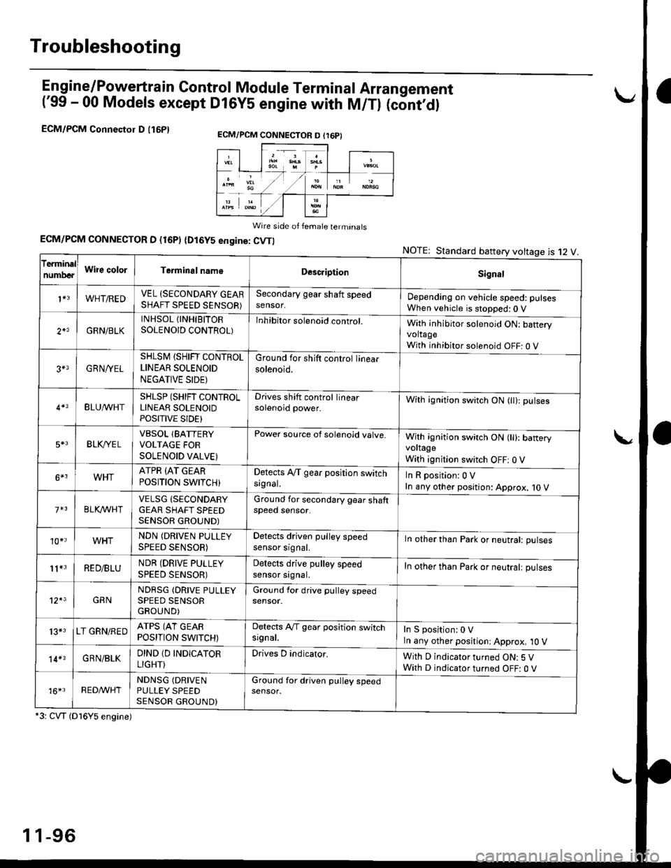
ECM/PCM Connectol D (16P1
Wire side of female terminats
ECM/PCM CONNECTOR D {16P) (Dl6YS engine: CVTI
*3: CVT (Dl6Y5 engine)
NOTE: Standard battery voltage is 12 V
ECM/PCM CONNECTON D (r6P)
f€rminal
numDeaWire colorTerminalnameDescriptionSignal
1+3WHT/REDVEL (SECONDARY GEARSHAFT SPEED SENSOR)
Secondary gear shaft speedsensor,Depending on vehicle speed: pulsesWhen vehicle is stopped:0 V
2*3GRN/BLK
INHSOL {INHIBITORSOLENOID CONTROL)Inhibitor solenoid control.With inhibitor solenoid ON: bafteryvoltageWith inhibitor solenoid OFF: 0 V
3+3GRN/YEL
SHLSM (SHIFT CONTROLLINEAR SOLENOID
NEGATIVE SIDE)
Ground for shift control linearsolenoid.
BLU^/vHTSHLSP (SHIFT CONTROLLINEAR SOLENOIDPOSITIVE SIDE}
Drives shift control linearsolenoid power.With ignition switch ON (tl): pulses
5*3BLK,/YE LVBSOL lBATTERYVOLTAGE FOR
SOLENOID VALVE)
Power source of solenoid valve.With ignition switch ON (ll): baneryvoltage
With ignition switch OFF: 0 V
6*3WHTATPR (AT GEAR
POSITION SWITCH)Detects A,/T gear position switchsrgnal.InRposition:0V
In any other position: Approx. 10 V
BLKA/VHIVELSG (SECONDARY
GEAR SHAFT SPEEDSENSOR GROUND)
Ground for secondary gear shaftspeed sensor.
10*.WHTNDN (DRIVEN PULLEY
SPEED SENSOR)
Detects driven pulley speedsensor srgnal.In other than Park or neutral: pulses
11*3RED/BLUNDR (DRIVE PULLEY
SPEED SENSOR)
Detects drive pulley speedsensor srgnal.In other than Park or neutralt pulses
12*3GRNNDRSG (DRIVE PULLEYSPEED SENSORGROUND)
Ground for drive pulley speedsensor.
13*3LT GRN/REDATPS (AT GEARPOSITION SWITCH)
Detects Ay'T gear position switchsrgnal.In S position:0 VIn any other positioni Approx, 10 V
14*3GRN/BLKDIND 1D INDICATOR
LIGHT)
Drives D indicator.With D indicator turned ON: 5 VWith D indicator turned OFF: O V
16*rRED^/VHTNDNSG (DRIVEN
PULLEY SPEEDSENSOR GROUND)
Ground for driven pulley speedsensor.
1 1-96
Page 1819 of 2189

How To Use This Manual
Circuit Schematics
oa
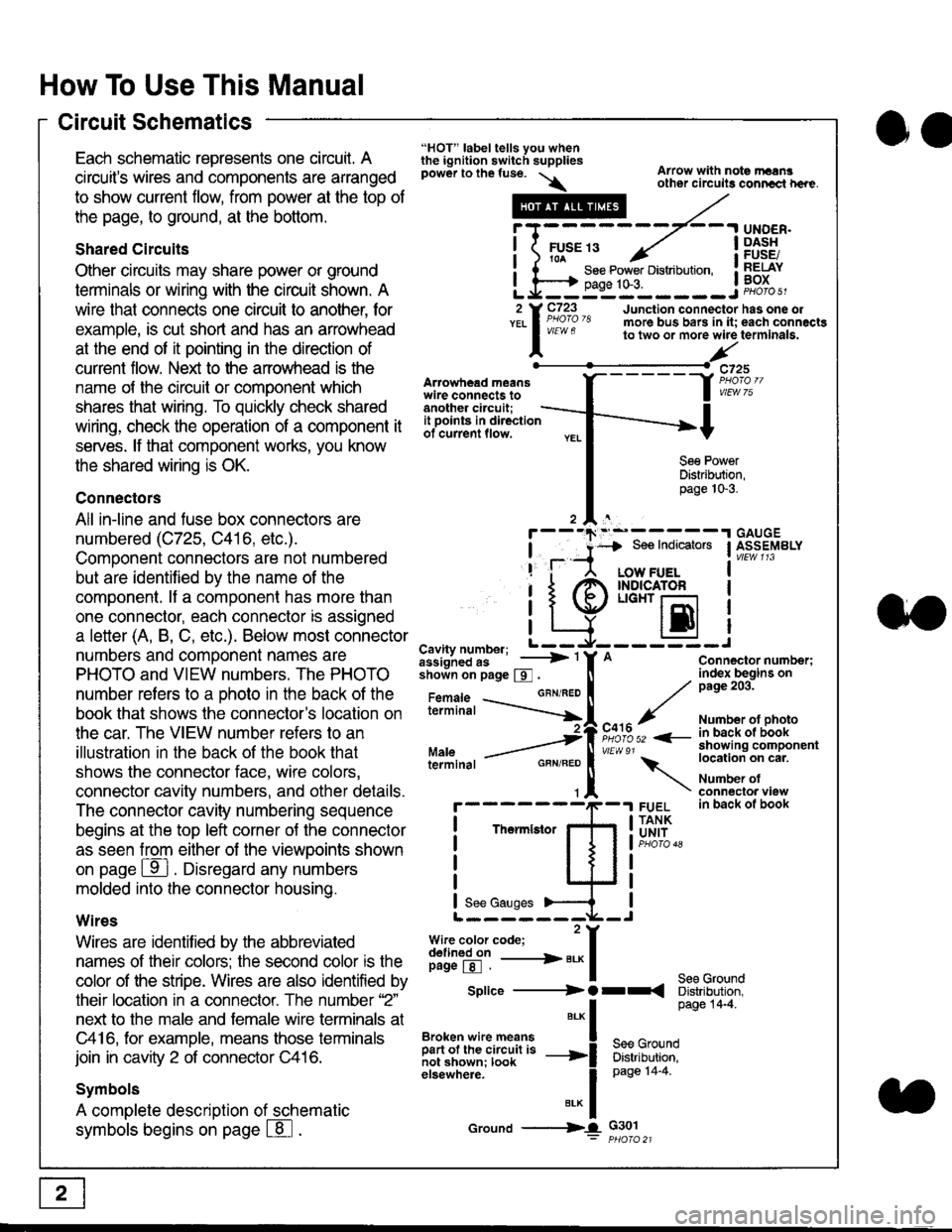
Each schematic represents one circult. A
circuit's wires and components are arranged
to show current flow, from power at the top of
the page, to ground, at the bottom.
Shared Circuits
Other circuits may share power or ground
terminals or wiring with the circuit shown. A
wire that connects one circuit to another, for
example, is cut short and has an arrowhead
at the end of it pointing in the direction of
current flow. Nelit to the anowhead is the
name o{ the circuil or comoonent which
shares that wiring. To quickly check shared
wiring, check the operation of a component it
serves. lf that component works, you know
the shared wiring is OK.
Connectors
All in-line and fuse box connectors are
numbered (C725, C416, etc.).
Component connectors are not numbered
but are identiJied by the name of the
component. lf a componenl has more than
one connector, each connector is assigned
a letter (A, B, C, etc.). Below most connector
numbers and comDonent names are
PHOTO and VIEW numbers. The PHOTO
number refers to a Dhoto in the back of the
book that shows lhe conneclor's location on
the car. The VIEW number refers to an
illustration in the back of the book that
shows the connector face, wire colors,
connector cavity numbers, and other details.
The connector cavity numbering sequence
begins at the top left corner oJ the connector
as seen from either of the viewooints shown
on page ffl . Disregard any numbers
molded into the connector housino.
Wires
Wires are identilied by the abbreviated
names of their colors; the second color rs the
color of the stripe. Wires are also identified by
their location in a connector. The number '2"
next to the male and female wire terminals at
C416, for example, means those terminals
join in cavity 2 of connector C416.
Symbols
A complete description of schematic
symbols begins on page | 8
"HOT" label tells you whenthe ignition switch suppliespower to the fuse. \
Artowhead meanswire connects toanother circuit;
Arrow with note rErngother circuils conncct h€re.
it .a
llu":: ^,{ ii t See Power Distribution, .I t----t oaqe tO-3. IL*--:--------J2 Y C723 Junction connectorYEL I Pao'o'8 more bus bars in it;
I - " " to two or more wire
l,/
-t>?
See PowerDistribution,page 10-3.
UNDER.DASHFUSE/RELAYBOX
has one oleach connactgterminala.
it ooints in directionof current flow.
TheImletor
t_I
Cavity number; L ---
Jiili'iJi!--' -----> '
shoin on page S .
Maleterminal
L?*?l?,-
"'"'I
c725
vlEUt/ 75
Connector number;index begins onpage 203.
Number ot photoin back ol bookshowing componentlocation on cat.
Number ofconneclor viewin back of book
7
GBN/FEO
See Ground
Soe Indicators I ASSEMBLY
:-------J
LOW FUELINDICATOFLIGHT r-l
EI
A
"o'r"/PHOTO 52 <-
\
FUELTANKUNIT
Splice ---------) O rr
".* I Page 14'4'
IBroken wire means | --^ -
iar";J.'It,;,rJ;ii; -----i Bffi,Bili*l
elsewhere. I 0a0e tn-a
IBrK Icround --->lL c301: ptioro 21