1996 HONDA CIVIC Carpet
[x] Cancel search: CarpetPage 52 of 2189

Unit of length: mm (in)
Fuel and Emission - Section
MEASUREMENTSTANOARO (NEW)
260 310 (2.7 - 3.2, 38 - 46)
260 - 310 (2.7 - 3.2, 38 - 46i
260 - 310 (2.7 - 3.2, 38 - 46)
210 - 320 Q.A - 3.3, 40 - 47 1
45 {11.9, 9.9)
M/T (neutral) I A/T or C\.T (lE or fd positioni
Fuel paessure
regulator
Pressure wilh fuel pressure regulator vacuum hose
disconnected kPa (kgvcm'�, Psi)D16Y5D 16Y7D16Y881642
FueltankCapacity I (US gal, lmp gal)
E ngineldle speed rpm
016Y5D16Y7D16Y8816A2
u.s.A.CanadaU,S,A.Canada
670 1 506701 50670150700 t 50
7501 507501 507501 50
700 t 50700 I 507001 50750150750 r 50
ldle CO %0.1 max.
Clutch - Serrtion 12
MEASUREMENTSTANDARD {NEWI I SERVICE LIMIT
Clutch pedalPedal height to floor
StrokePedal play
Disengagement height to floorto carpet
16s (6 1/2)130 140 (5 1/8 5 1/2)
12 -21 t1l2 - 13/16183 (3 1/4)44 (1 3/4) min. Reference
FlywheelClutch surface ruoout
Rivet head depthThickness
0.05 (0.002) max.0.15 (0.006)
Clutch disc1.3- 1.9 (0.05 - 0.07)
8.5 - 9.1 (0.33 - 0.36)
0.2 {0.01)5.5 (0.22)
Pressure plateWarpageDiaphragm spring fingers alignment
0.03 (0.001) max0.6 (0.02) max
0.15 (0.006)
1.0 (0.04)
Lro
3-7
lfllHlllllllllrltllli[
Page 352 of 2189

lf the inspection for a particular code requires voltage or resistance checks at the ECM/PCM connectors, remove the right
kick panel. Pull the carpet back to expose the ECM/PCM. Remove the ABS control unit if so equipped. unbolt the EcM/
PCM bolt. Turn the ignition switch oFF, and connect the backprobe sets and a digital multimeter as described below
check the system according to the procedure described for the appropriate code(s) listed on the following pages'
The illustrationshows '96 - '98 models.
How to Use lhe Backprobe Sets
connect the backprobe adapters to the stacking patch cords, and connect the cords to a multimeter. using the wire insula-
tion as a guide for the contoured trp of the backprobe adapter. gently slide the tip into the connector from the wire side
until it comes in contact with terminal end of the wire'
BackProbe
BACKPROEE SET
07SAZ - 001000A lTwo
DIGITAL MULTIMETER(Commercially avail.bleI orKs - AHM - 32 - oo3 (cont'd)
KICK PANEL
1 1-83
Page 1159 of 2189
)
Brake Pedal
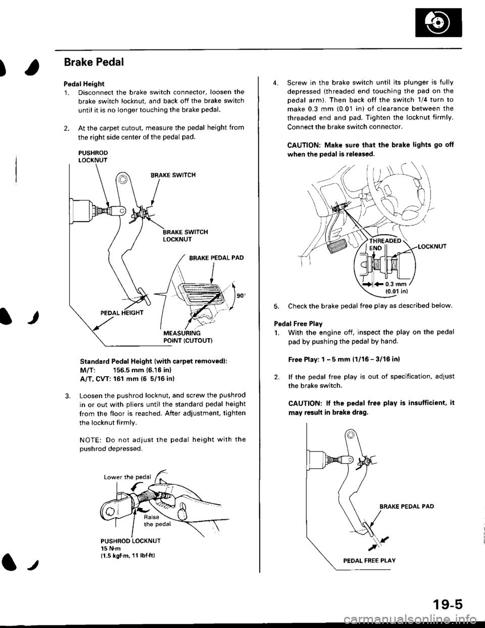
Pedal Height
1. Disconnect the brake switch connector, loosen the
brake switch locknut, and back off the brake switch
until it is no longer touching the brake pedal,
2. At the carpet cutout, measure the pedal height from
the right side center of the pedal pad.
PUSHRODLOCKNUT
Standard Pedal Height (with carpet removed):
M/T: 156.5 mm 16.16 inl
A/T, CVT: 161 mm (5 5/16 in)
3. Loosen the pushrod locknut, and screw the pushrod
in or out with pliers until the standard pedal height
from the floor is reached. After adjustment, tighten
the locknut firmly.
NOTE: Do not adiust the pedal height with the
Dushrod depressed.
It
PUSHROO LOCKNUT15 N.m(1.5 kgf.m. 11 lbI.ft)
POINT ICUTOUTI
4. Screw in the brake switch until its plunger is fully
depressed (threaded end touching the pad on the
pedal arm). Then back off the switch 1/4 turn to
make 0.3 mm (0.01 in) of clearance between the
threaded end and pad. Tighten the locknut firmly.
Connect the brake switch connector.
CAUTION: Make sure that the brake lights go off
when the pedal is released.
LOCKNUT
5. Check the brake pedal free play as described below.
Pedal Free Plsy
1. With the engine off, inspect the play on the pedal
pad by pushing the pedal by hand.
Free Play: 1 - 5 mm (1/16 - 3/16 inl
2. lf the pedal free play is out of specitication, adjust
the brake switch.
CAUTION: lf the pedal free play is insufficient, it
may result in brake drag.
BRAKE PEDAL PAO
)
19-5
*0.3 mm(0.01 in)
Page 1288 of 2189
Interior
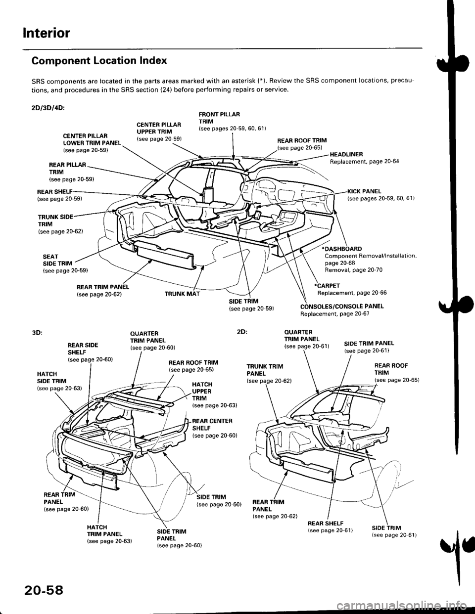
Component Location Index
SRS comDonents are located jn the parts areas marked with an asterisk (*). Review the SRS component locations, precau
tions, and procedures in the SRS section {24) before performing repairs or service.
2Dl3Dl4Dl
CENTER PILLARUPPER TRIM{see page 20 591
FRONT PILLARTRIM{see pages 20 59,60,61)
REAR PILLARTRIM
TRUNKTRIM(see page 20-62)
SEATSIDE TRIM{see page 20-59)
{see page 20 59}
CENTER PILLARLOWER TRIM PANEL(see page 20-59)
REAR ROOF TRIM(see page 20-65)
:
OUARTERTRIM PANEL
{see page 20'61)
HEADLINERReplacement, Page 20'64
*OASHBOARO
Component Removal/lnstallation,page 20 68
REARlsee page 20 59)
REAR TRIM PANEL
lsee page 20-62)
Removal, page 20-70
*CARPET
Replacement, page 20 66
PANELReplacement, page 20-67
3D:
REAR SIDESHEI-F(see page 20-60)
OUARTERTRIM PANEL(see page 20-60)SIDE TRIM PANEL(see page 20-6'l)
2Dl
HATCHSIDE TRIM(see pase 20 63)
REAR ROOF TRIM(see page 20 65)REAR ROOFTFIM(see page 20'65)HATCHUPPERTRIMlsee page 20 63)
CENTERSHELFlsee page 20 60)
REARPANELlsee page 20 60)
SIDE TRIM{see page 20 60)REARPANEL(see page 20 62)
1
HATCHTRIM PANEL(see page 20-63)
SIDE TRIMPANEL(see page 20-60)
20-54
Page 1296 of 2189
Carpet
Replacement
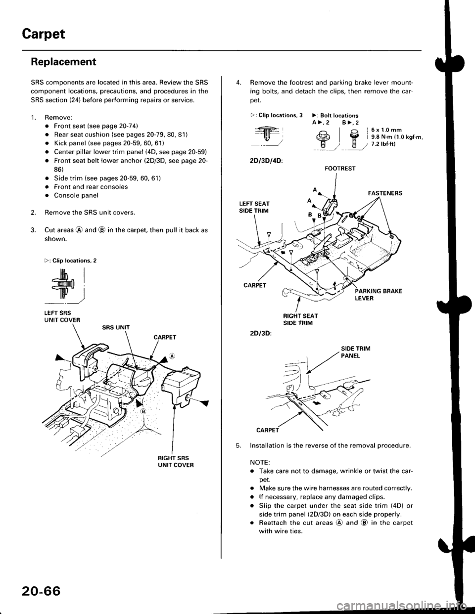
SRS components are located in this area. Review the SRS
component locations, precautions, and procedures in the
SRS section {24} before performing repairs or service.
1. Remove:
. Front seat (see page 2O-7 4l
. Rear seat cushion (see pages 20 79, 80, 81)
o Kick panel (see pages 20-59, 60, 61)
o Center pillar lowertrim panel i4D, see page 20-59)
. Front seat belt iower anchor (2Dl3D, see page 20-
86)
. Side trim (see pages 20-59, 60,61)
o Front and rear consoles
. Console panel
Remove the SRS unit covers.
Cut areas @ and @ in the carpet, then pull it back as
snown.
>: Clip locations,2
2.
3.
-lM- IlMt l
ry-l
LEFT SRSUNIT COVER
20-66
4. Remove the tootrest and parking brake lever mount-
ing bolts, and detach the clips, then remove the car
pet.
>:Clip localions,
:ft
\/l
2D l3D l4D:
3 >: Bolt locationsA>.2 A>,2
3 l6x10mm
e2 Y 9.8 N.m r1.o kgr'm,
H ) E / 7.2tbtrtl::a /
5.
2D I3D:
Installation is the reverse of the removal procedure.
NOTE:
. Take care not to damage. wrinkle or twist the car-
pet.
. Make sure the wire harnesses are routed correctly.
. lf necessary, replace any damaged clips.
. Slip the carpet under the seat side trim (4D) or
side trim panel (2Dl3D) on each side properly.
. Reattach the cut areas @ and @ in the carpet
with wire ties.
FOOTREST
SIOE TBIM
Page 1338 of 2189
Opener Cables
Replacement
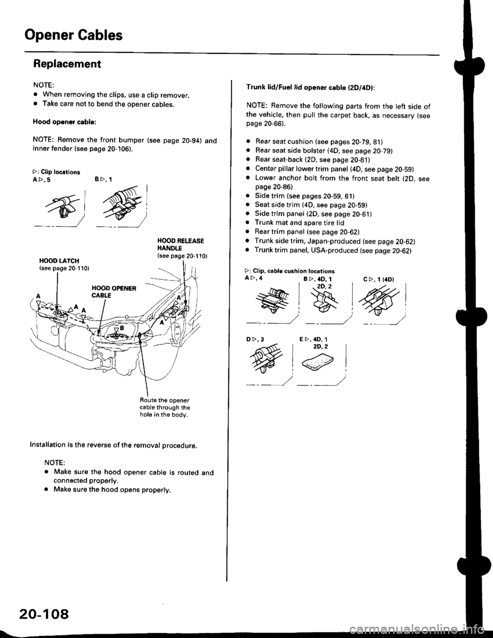
NOTE:
t When removing the clips. use a clip remover.. Take care not to bend the opener cables.
Hood op€ne. cable:
NOTE; Remove the front bumper (see page 20-94) andinner fender (see page 20-106).
>: Clip loc.tionsA >,5 B>, 1
ry)
g
HOOD REI.TASEHANDI.I(see page 20-110)
cable through thehote in th6 body.
Installation is the reverse of the removal procedure.
NOTE:
a Make sure the hood opener cable is routed andconnected properly.
. Make sure the hood opens properly.
20-10a
Tlunk lid/Fuel lid opener cabte (2Dl4D):
NOTE: Remove the following parts from rhe Ieft side ofthe vehicle, then pull the carpet back, as necessary {seepage 20-66).
. Rear seat cushion (see pages 20-79, 81). Rear seat side bolster (4D, see page 20,79). Rear seat-back (2D, see page 20-81). Center pillar lower trim panel (4D, seepage20-59)o Lower anchor bolt from the front seat belt {2D. seepage 20-86)
. Side trim (see pages 20-59, 61). Seat side trim (4D, see page 20-59). Side trim panel (2D, see page 20-61). Trunk mat and spare tire lid. Reartrim panel (see page 20-62). Trunk side trim, Japan-produced (see page 20-62). Trunk trim panel, USA-produced (see page 20-62)
>r Clip, cable cushion locationsA >,4 B >,4D_ 1c >, 1 l4D)2D,2
t@#lB
_ : _/ _-___)
E >,4D, 12D,2
@i
_ _,, -/
D>,3
Page 1340 of 2189
Opener CablesOpener and Latch
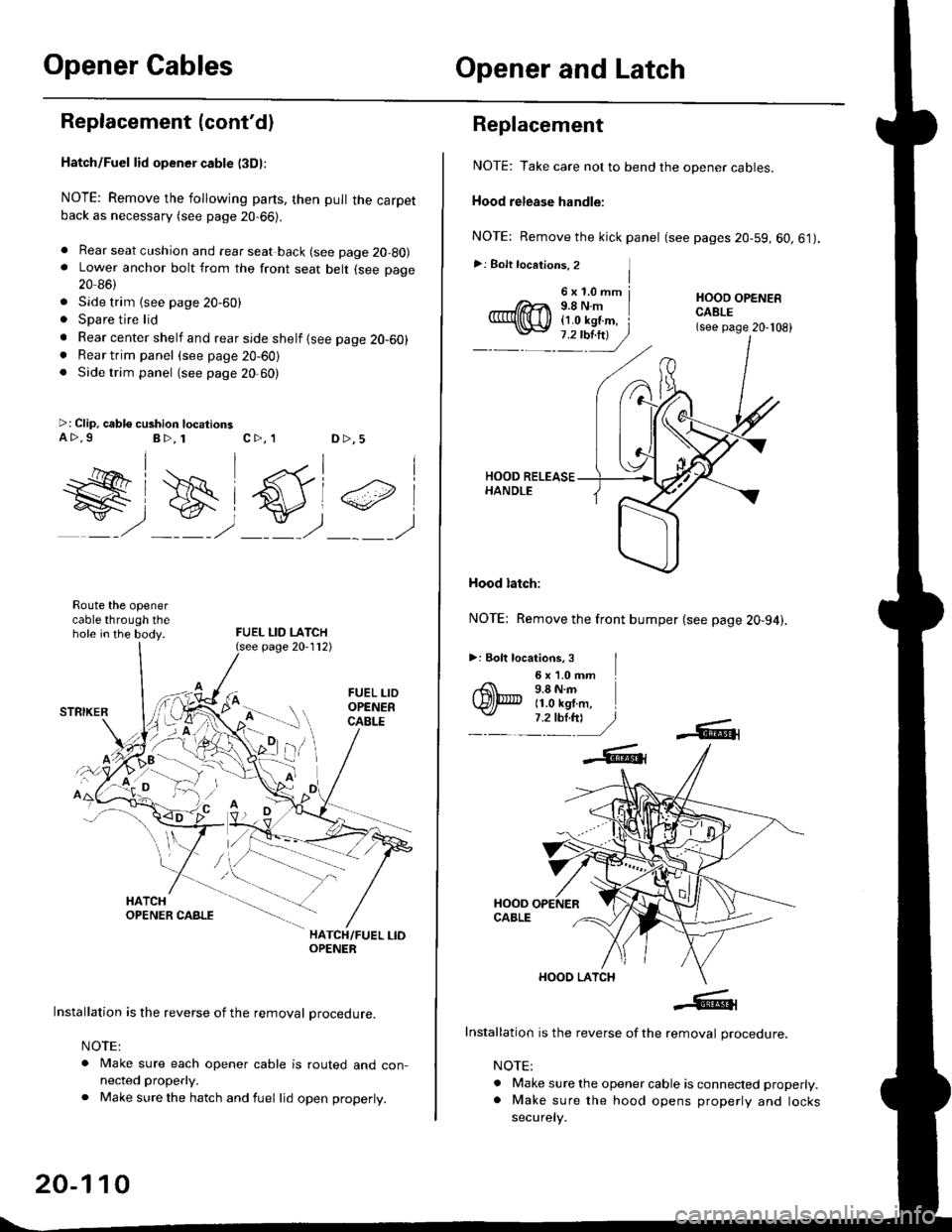
Replacement (cont'dl
Hatch/Fuel lid opener cable l3Dl:
NOTE: Remove the following parts, then pull the carpetback as necessary (see page 20-66).
. Rear seat cushion and rear seat back (see page 20-80). Lower anchor bolt from the front seat belt (see page
20 86)
. Side trim {see page 20-60). Spare tire lid
. Rear center shelf and rear side shelf {see page 20-60). Rear trim panel (see page 20-60). Side trim panel (see page 20,60)
>: Clip, cable cushion locationsa>.9B>, 1c>, 1D >,5
W#)
FUEL LID LATCH
#,
Route the openercable through thehole in the body.
HATCH/FUEL LIOOPENER
Installation is the reverse of the removal procedure.
NOTE:
. Make sure each opener cable is routed and con-nected properly.
. Make sure the hatch and fuel lid open properly.
page 20-112)
20-110
6x1.0mm j9.8Nm{1.0 kgf.m, i
Replacement
NOTE: Take care not to bend the opener cables.
Hood release handle:
NOTE: Remove the kick panel (see pages 20-59, 60.61).
>: Bolt locations, 2 ]I
HOOO OPENERCABLE(see page 20-108)
Hood latch:
NOTE: Remove the front bumper (see page 20-94).
>: Eolt locations, 3 I6 x '1.0 mm9.8 N.m11.0 kgf.m,
Installation is the reverse of the removal procedure.
NOTE:
. Make sure the opener cable is connected properly.. Make sure the hood opens properly and locks
securely.
Page 1357 of 2189
Front Seat Belt
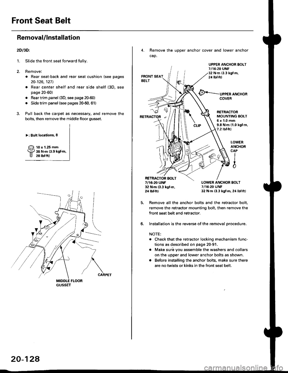
RemovaUlnstallation
2D l3Dl
1. Slide the front seat forward fully.
2. Remove:
. Rear seat-back and rear seat cushion (see pages
20-126,127l.
. Rear center shelf and rear side shelf (3D, see
page 20-60)
. Resr trim panel (3D, see page 2G60)
. Side trim panel (see pages 20-60, 61)
3. Pull back the carpet as necessary, and remove the
bolts, then remove the middle floor gusset.
>: Boh locations,8
10 x 1.25 mm38 N.m (3.9 kgf'm,28 rbtftl
20-124
4. Remove the upper anchor cover and lower anchor
cap.
UPPER ANCHOR EOLT7/16-20 UNF32 N.m {3.3 kgf.m,24 tbf.ftt
UPPER ANCHORCOVER
LOWERANCHOBCAPIIio
RETRACTORMOUNTING BOLT6x1.0mm9.8 N.m (1.0 kgf.m.7.2 tbl.hl
LOWER ANCHOR BOLT7/16-20 UNF32 N.m (3.3 kgt.m, 24 lbf.ft)
Remove all the anchor bolts and the retractor bolt.
remove the retractor mounting bolt, then remove the
Iront seat belt and retractor.
Installation is the reverse of the removal orocedure.
NOTE:
. Check that the retractor locking mechanism func-
tions as described on page 20-91
o Make suri vou assemble the washers and collars
on the upper and lower anchor bolts as shown.
. Before installing the anchor bolts, make sure there
are no twists or kinks in the front seat belt.
RETRACTOR AOLT7/16-20 UNF32 N.m 13.3 kgf.m,24 tbttrl
6.