Page 982 of 2189
I
6. Disconnect the vehicle speed sensor (VSS) connec-
tor, the driven pulley speed sensor connector, and
the secondary gear shaft speed sensor connector.
SECONDARY GEARSHAFT SPEEDORIVEN PULLEY
SPEED SENSORCONNECTORSENSOR
7. Remove the transmission housing mounting bolts.
14-305
8. Remove the drain plug, and drain th€ CVT fluid
Reinstall the drain plug with a new sealing washer.
CAUTION: While installing the drain plug' bo 3ur.
nol io allow du3l 8nd other toreign particles to
enter into th€ trsnsmi$ion.
DRAIN PLUG18 x 1.5 rnm(, N.m (5.0 kgfm, 36 lbf'ft|
9. Remove the splash shield.
SEALING WASHERReplaco.
Page 983 of 2189

Transmission
Removal (cont'd)
10. Remove the cotte. pins and castle nuts, then separatethe ball joints from the lower arm (see section 1g).
SELF-LOCKING -=V,
NUT \Replace. oitupea rOax
Remove the right damper fork bolt, then separateright damper fork and damper.
Pry the right and left driveshafts out of the differen-tial.
Pull on the inboard joint to remove the right and leftdriveshafts (see section 16).
Tie plastic bags over the driveshaft ends.
NOTE: Coat all precision finished surfaces with cleanengine oil.
Remove the exhaust pipe A.
/\<,\CASTLE I{UT COTTERReplac6.
't 1.
't2.
tJ.
14.
q.
SELF.LOCKINGNUTReplace.
SELF.LOCKING NUTReplace.
14-306
EXHAUST PIPE A
19.
'16, Remove the right front mounvbracket,
ATF COOLER HOSE
17. Remove the ATF cooler hoses at the ATF coolerlines. Turn the ends of the ATF cooler hoses uo toprevent CVT fluid from flowing out, then plug theATF cooler hoses and lines,
NOTE: Check for any sign of leakage at the hosejoints.
18. Remove the engine stiffeners and the flywheel cover.
Remove the eight drive plate bolts one at time whilerotating the crankshaft pullev.
ENGINE STIFFENER
Page 990 of 2189

6) TRANSMISSION HOUSING GASKET Replace'
@ DOWEL PIN
@) ATF FEED PIPE
@ o-RING Replace.
60 o-RING Replace.
@) DRIVE PULLEY SPEED SENSOR
@ TRANSMISSION HANGER
@ SNAP RING
@ txaust Sxtfu, zs t 31 mm selective part
@ SALL BEARING
6J RING GEAR6D SNAP RING
@ aevense aRlxe rND PLATE Selective part
@ REVERSE BRAKE DISC
@ REVERSE BRAKE PLATE
@ DISC SPRING6} THNUST WASHER
@} finusr NeeoLr eelnNc
@ THRUST WASHER
@ GARRIER ASSEMBLY
@ THRUST WASHER
@ THRUST NEEDLE BEARING
@} SUN GEAR
@ SEALING RING REPIACE'
@ NEEDLE BEARING
@ INPUT SHAFT
@ NEEDLE BEARING
@ SEALING RING FEPIACE'
@ SEALING RING {RUBBERI Replace'
@ ATF FEED PIPE
O END COVER
O ATF FEED PIPE
O DOWEL PIN
@ O-RING Replace.G) FEED PIPE FLANGE
@ reeo ppe ruruce puru
O] ROLLERO IruTENMEDNTE XOUSING ASSEMBLY
ao corutnoL sxlrr lsseugLv
@ tnlrusmtsstottt ttoustt'tc
@ SHIFT CABLE BRACKET
c) BREATHER CAP
@ oll- SEAL Replace.
@ CONTROL LEVER
G LoCK WASHER Replace.(D secololaY ceaR SHAFT SPEED sENsoR
o) onvel put-uv sPEED SENSOR
@ O-RING Replace.(O SNAP RING6 rnmrsutsstoru xouslNc oRlvEN PULLEY
SHAFT ROLLER BEARING
@ END COVER GASKET REPIACE'
@ o-RING Replace
6o mnruulL vnLVe goDY LINE A
64 MANUAL VALVE BODY LINE B
@ O-RING Replace.
@ DETENT SPRING
O ATF FEED PIPE
@ O-RING Replace.
@ MANUAL VALVE EODY
@ DOWEL PIN
@ r'rllull valve goDY SEPARAToR PLATE
6D SNAP RING
@t roRwlno cturcx ASSEMBLY
@ o-RING Replace
@ SNAP RINGo3 spnlruc aetlrupn/RETURN SPRING ASSEMBLY
@ nevense ennr eBtottt
@ o-RING Feplace.
@ SNAP RING RE'AINER
@ ATF FEED PIPE
.1,
TOROUE SPECIFICATIONS
6x1.0mm
6x1.0mm
8 x 1.25 mm
8 x 1.25 mm
8 x 1.25 mm
12 N.m (1.2 kgf'm,8.7 lbf'ft)
14 N.m {1.4 kgf'm, 10 lbift)
37 N.m (3.8 kgf'm, 27 lbf'ft)
26 N.m (2.7 kgf'm,20 lbf'ft)
29 N.m (3.0 kgf'm, 22 lbf'ft)
6B
8B
8F
8G
14-313
rl,
Page 993 of 2189
Transmission Housing/Flywheel Housing
Removal
NOTE:
. Cleanall parts thoroughly in solvent or carburetor cleaner, and dry with compressed air.. Blow out all passages.
. When removing the transmission housing/flywheel housing, replace the following:- O-rings- Secondary drive gear assembly- Sta rt clutch assemblv- Flywheel housing gasket
ATF PASSAGE LINEHOLD€R ASSEMBLY
IX)WEL PIN
OIFFERENTIAL ASSEMBLY
SNAP RING
COTTER RETAINER
COTTERS, 25.5 mmSelective part
8 x 125 mm BOLT
O.RINGRsplaco.
VWHEEL HOUSING
EYWIIEEL HOUSING GASKETRoolace.
START CLUTCHASSEMBLYReplace.
ATF PA$gAGEUNE ASSEMBLY
6 x 1,0 mm BOLT
O.RINGReplace.
ATF PUMP DRIVE CHAIN
SNAP RING
THRUST SHIM,25x35mmSeloctive part
SECONDARYGEAR SHAFT
SECONDARY DRIVEGEAR ASSEMBLYReplace.
PARKPAWL SHAFT
THRUST SHIM, 22 r 28 mmSeloctive partGRII{GSReplac€.6 x 1.0 mm BOIT
ATF PUMP DRIVESPROCKET
PfTOT FLANGE
ATF PUMP DRTVESPROC|(ET HUB
THRUST WASHERS
PARK PAWLSPRING
INPUT SHAFT
14-316
DRIVEN PULLEY SHAFT
InANSMISS|O]{ HOUSTNG
Page 994 of 2189

)
1.Remove the ATF passage line holder assembly'
Remove the flywheel housing (twenty bolts)'
Remove the ATF passage line assembly (one bolt)
Remove the ATF pump drive sprocket (three bolts),
then remove the ATF pump drive chaan.
Move the pitot flange toward its cutout, then remove
the pitot flange.
PITOT PIPE
Remove the snap ring securing the ATF pump drlve
sprocket hub. then remove the 22 x 28 mm thrust
shim, the ATF pump drive sprocket hub and the thrust
wasners,
Remove the differential assemblY.
Remove the park pawl shaft, the park pawl spring,
and the park Pawl'
Remove the snap ring securing the start clutch, then
remove the cotter retainer and the cotters.
7.
9.
J
14-317
10. Set the special tool on the start clutch' and attach the
oawl of the special tool to the park gear securely as
shown.
CAUTION:
. Do not place tho pawl of the spocial tool on the
start clutch guidc. ll the pawl ot the spocial tool
contacts the 3tart clutch guid€, the start clutch
guido may be damaged.
. Be sure not to allow dust and other foreign par-
ticles to enter into the drivon pull6y shaft'
START CLUTCHREMOVER07TAE - P4V0120
11.Remove the start clutch and the secondary drive
gear assembly using the special tool, then remove
the secondary gear shaft.
START CLUTCHREMOVER07TAE - P4V0120
START CLUTCHASSEMBLYReplace.
START CLUTCHASSEMBLY
PAWL
Page 996 of 2189

l.
1.
2.
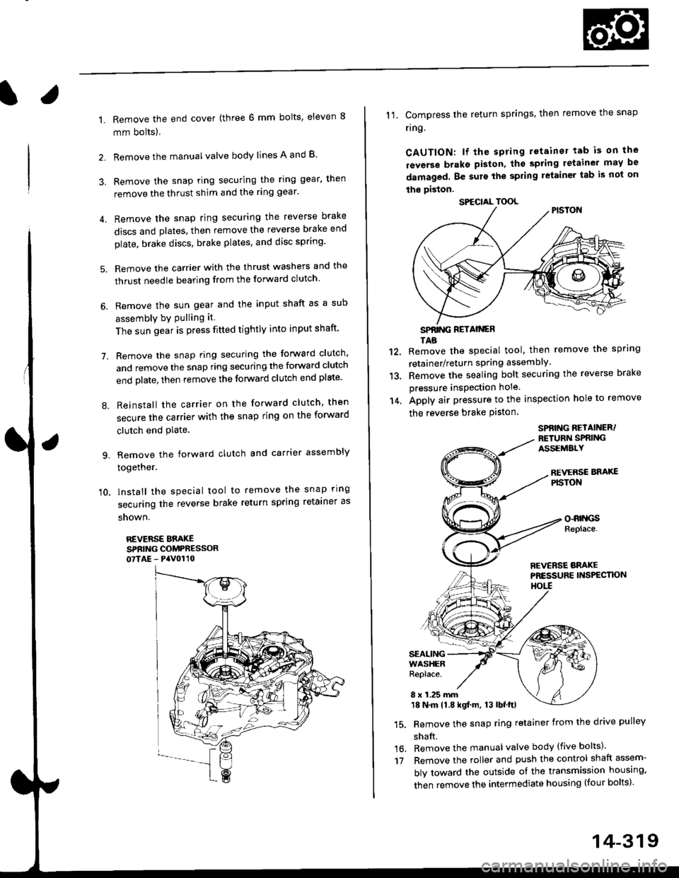
Remove the end cover {three 6 mm bolts, eleven 8
mm bolts).
Remove the manualvalve body lines A and B
3. Remove the snap ring securing the ring gear, then
remove the thrust shim and the ring gear'
4. Remove the snap ring securing the reverse brake
discs and plates, then remove the reverse brake end
plate. brake discs, brake plates, and disc spring'
5. Remove the carrier with the thrust washers and the
thrust needle bearing from the forward clutch
6. Remove the sun gear and the input shaft as a sub
assembly bY Pulling it
The sun gear is press fitted tightly into input shaft'
7. Remove the snap ring securing the forward clutch,
and remove the snap ring securing the forward clutch
end plate, then remove the forward clutch end plate'
8. Reinstall the carrier on the forward clutch, then
secure the carrier with the snap ring on the forward
clutch end Plate.
9. Remove the forward clutch and carrier assembly
together.
'10. lnstall the special tool to remove the snap ring
securing the reverse brake return spring retainer as
snown.
REVERSE BBAKESPRING COMPRESSOR07TAE - PaV0110
11. Compress the return springs. then remove the snap
ring
CAUTION: lf the spring retainer tab is on the
rsverse braks piston, tho spting letainer may be
damaged. Be surs the spring letainer tab is not on
the piston.
SPfiING FETAIiGRTAB
Remove the special tool, then remove the spring
retainer/return spring assembly.
Remove the sealing bolt securing the reverse brake
pressure insPection hole.
Apply air pressure to the inspection hole to remove
the reverse brake Piston
12.
13.
14.
16.'t7
SPBING REYAINER/RETURiI SPRIiIGASSEMALY
REVERSE BNAXEPISTON
o-RrllcsReplace.
FCVERSE BRAKEPRESSURE INS?ECTK)NHOtl
SEALINGWASHERReplace.
8 x 1.25 mm18 N.m 11.8 kgf.m, 13 lbf.ttl
Remove the snap ring retainer from the drive pulley
shaft.
Remove the manual valve body (five bolts)'
Remove the roller and push the control shaft assem-
bly toward the outside of the transmission housing,
then remove the intermediate housing (four bolts)'
SPECIAL TOOL
14-319
Page 1010 of 2189
Flywheel Housing
Input Shaft Oil Seal
l.
8. Install the oil seal in the transmission housing using
the sDecial tools as shown.
DRIVER07749 - 0010d)0
9.Install the oil seal in the flywheel housing using the
soecial tools as shown.
PILOT,26x30mmoTJAD - PH80200DRIVERATIACHMENT, 58 x 72 rnin
0?947 - d'40201
Replacement
1. Remove the input shaft oil seal from the flywheel
housing.
OIL SEAL
Instali the oil seal in the flywheel housing using the
soecialtools as shown.
FLYWHEEL
lmtalled depth:2.5- 3.5 mmro"nri':,ilii.rl
t@
14-333
Page 1011 of 2189

Transmission Housing Bearings
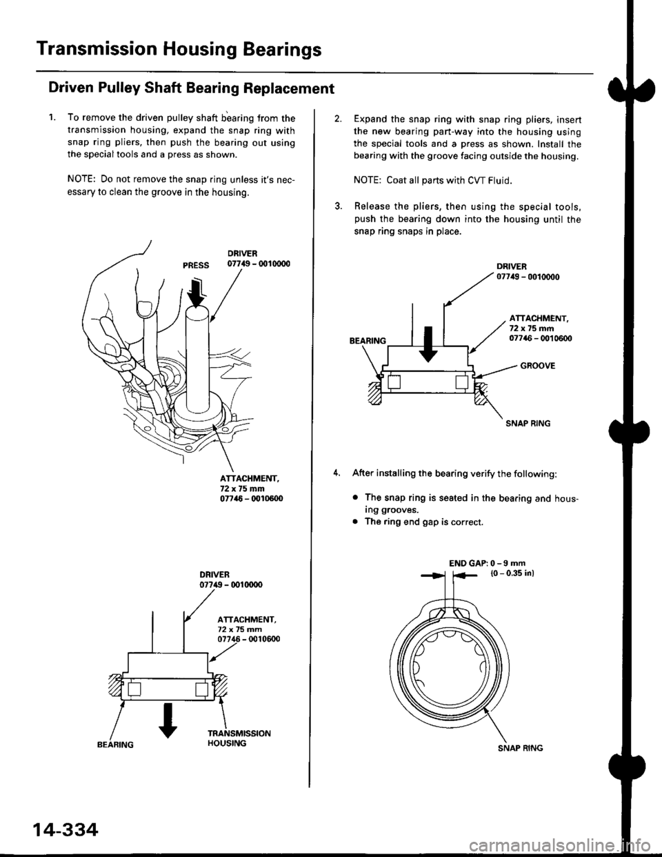
Driven Pulley Shaft Bearing Replacement
1. To remove the driven pulley shaft b'earing trom the
transmission housing, expand the snap ring with
snap ring pliers, then push the bearing out using
the specialtools and a press as shown.
NOTE: Do not remove the snap ring unless it's nec-
essary to clean the groove in the housing.
07749 - 001(xDo
ATTACHMENT,72x75mm07746 - (x'l05U)
077i() - 001(xrco
14-334
SNAP RING
Expand the snap ring with snap ring pliers, insert
the new bearing part-way into the housing using
the special tools and a press as shown. Install the
bearing with the groove facing outside the housing.
NOTE: Coat all pans with CW Fluid.
Release the pliers, then using the special tools,push the bearing down into the housing until the
snap ring snaps in place.
BEARING
ATTACHMENT,72x75mm07746 - OO1 0600
GROOVE
SNAP RING
After installing the bearing verify the following:
o The snap ring is seated in the bearing and hous-
ing grooves.
. The ring end gap is correct.
END GAP| 0 -9 mm
l0 - 0.35 inl