Page 1053 of 2189
Intermediate Shaft
Removal
Drain the transmission oil or fluid {see section 13 or
r 4).
Remove the left driveshaft (see page 16-3).
Remove the three dowel bolts.
OOWEL BOLTS'10 x 1.25 mm
Remove the intermediate shaft from the differential.
CAUTION: Hold the intermsdiate shaft horizontal
until it is clear of lhe dilterential to prevent damage
to the differential oil seal.
'1.
2.
3.
INTERMEDIATE SHAFT
16-20
Disassembly
NOTE: Be careful not to damage the metal rings on theintermediate shaft during disassembly.
1. Remove the set ring.
2. Remove the intermediate shaft outer seal from theDeaflng suppon.
3. Remove the external circlip,
Page 1054 of 2189
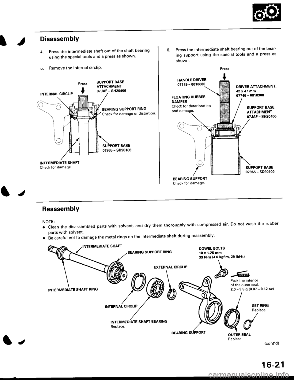
Disassembly
Press the intermediate shaft out of the shaft bearing
using the special tools and a press as shown.
Remove the internal circliP
Press
I
SUPPORT BASEATTACHMENT07JAF - SH20400INTERNAL CIBCLIP
BEARING SUPPORT RING
Check for damage or distortion
6. Press the intermediate shaft bearing out ot the bear-
ing support using the special tools and a press as
shown.
HANOLE DRIVER
0?749 - 00'�10000
Press
I
DRIVER ATTACHMENT,12x47 mm07746 - 0010300FLOATING RUBBEB
DAMPERCheck for deterioration
and oamage.SUPPORT BASE
ATTACHMENT07JAF _ SH20it00
BEARING SUPPORT
Check for damage
I sErR'NG
A4 Reolace
VUOUTER SEALReplace.(cont'd)
ReassemblY
NOTE:
. clean the disassembted parts with solvent, and dry them thoroughly with compressed air' Do not wash the rubber
parts with solvent.
. Becareful not to da mage the metal ringson the intermediate shaftduring reassembly'
BEARING SUPPORT RINGDOWEL BOLTS10 x 1.25 mm39 N.m 14.0 kgf.m,29 lbIftl
EXTERNAL CIRCLIP
Pack the interiorof the outer seal.2.0-35s10.07-012oz)
INTERNAL CIRCLIP
INTERMEDTATE SHAFT BEARING
Replace,
INTERMEDIATE SHAFT RING
lJ
16-21
Page 1055 of 2189
lntermediate Shaft
Reassembly (cont'd)
1. Press the intermediate shaft bearing into the bear-ing support using the special tools and a press asshown.
Prass
I
DRIVER ATTACHMENT,52x55mm07746 - 001 0(X)
Seat the internal circlip in the groove of the bearingsuppon.
Press the intermediate shaft into the shaft bearingusing the special tools and a press.
Praa.r
I
@---
LJ
INTERMEDIATE SHAFT
DRIVER ATTACHMENT,35 mm LD.
16-22
Seat the external circlip in the groove of the inter-mediate shaft.
Install the outer seal into the bearing support usingthe special tools as shown.
NOTE: Install the seal ftush with the bearing sup-port.
Pre$
t HANDr.r DRTVER- 0011r(x)0
Pack the Interiorof the ouler seal.2.0- 3.5 g {0.07 -0.12 ozl
OUTEN SEAL
Install the new set ringgroove.
ORIVER ATTACHMENT,52x55mm077i16 - 0010/O0
in the intermediate shaft
Page 1066 of 2189
Steering Gearbox
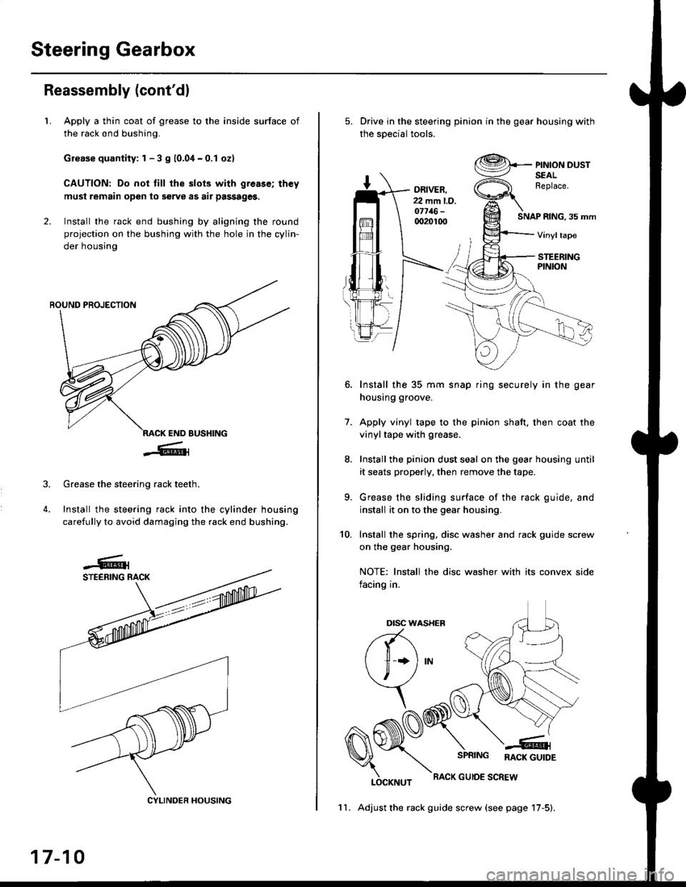
Reassembly (cont'dl
LApply a thin coat of grease to the inside surface of
the rack end bushing.
Grease quantity: 1 - 3 S 10.04-0.1 ozl
CAUTION: Do not till the slots with greas€; th€y
must remain open to serve as air passages,
Install the rack end bushing by aligning the round
projection on the bushing with the hole in the cylin-
der housing
4.
Grease the steering rack teeth.
Install the steering rack into the cylinder housing
carefully to avoid damaging the rack end bushing.
CYLINDER HOUSING
17-10
11. Adjust the rack guide screw (see page 17-5).
Drive in the steering pinion in the gear housing with
the soecial tools.
ORIVER.22 mm l.D.o7716-qr20100SNAP RING, 35 mm
PINION DUSTSEALReplace.
Vinyltape
STEERINGPINION
7.
Install the 35 mm snap ring securely in the gear
housing groove.
Apply vinyl tape to the pinion shaft, then coat the
vinyltape with grease.
Install the pinion dust seal on the gear housing until
it seats properly, then remove the tape.
Grease the sliding surface of the rack guide, and
install it on to the gear housing.
Install the spring, disc washer and rack guide screw
on the gear housing.
NOTE: Install the disc washer with its convex side
facing in.
LOCKNUT
SPRING RACK GUTDE
RACK GUIOE SCREW
10.
Dtsc w,
a(-\
l1 *l
\, ,/
\
Page 1073 of 2189
)
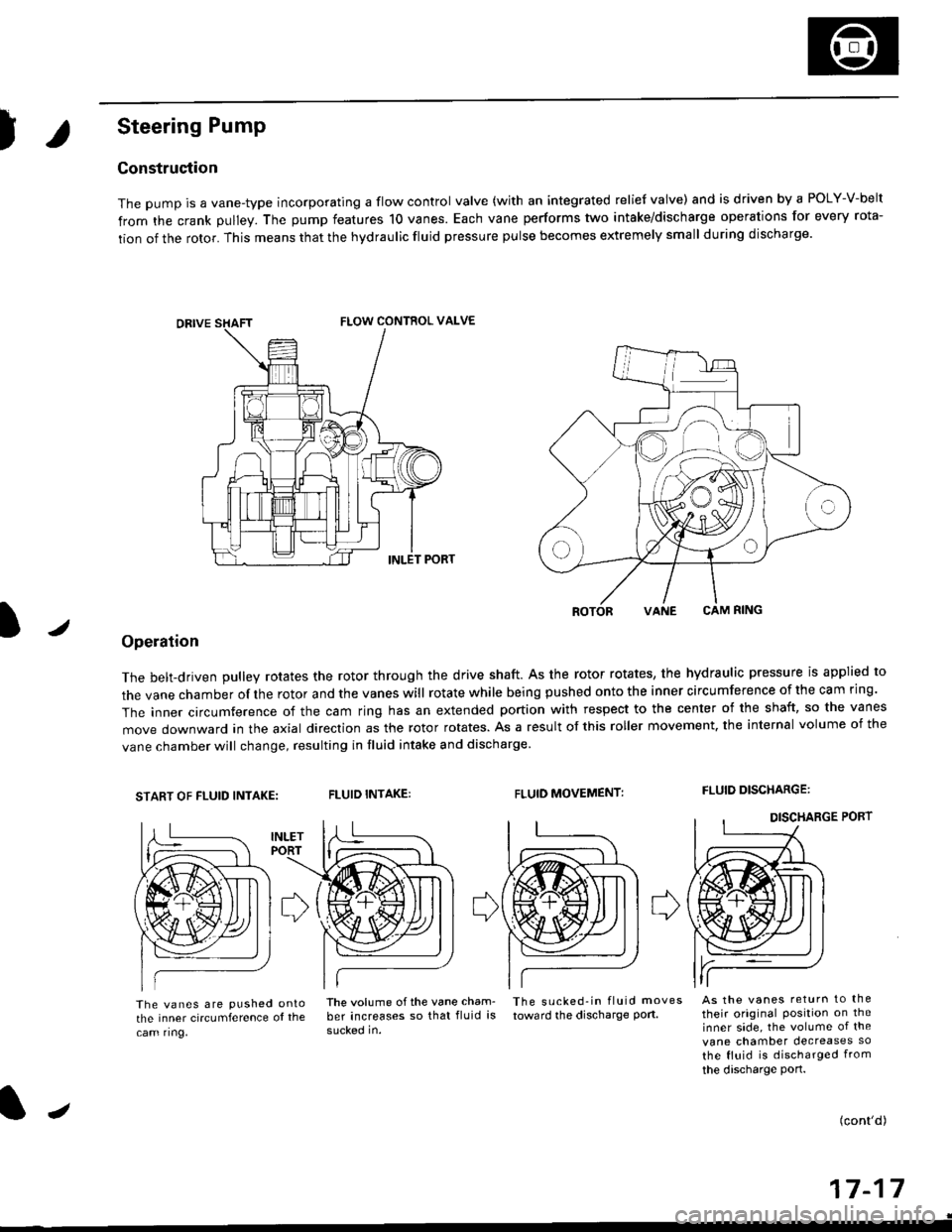
Steering Pump
Construction
The pump is a vane-type incorporating a flow control valve (with an integrated relief valve) and is driven by a POLY-V-belt
from the crank pulley. The pump features 10 vanes. Each vane performs two intake/discharge operations for every rota-
tion of the rotor. This means that the hydraulic fluid pressure pulse becomes extremely small during discharge.
/
ROTORVANE CAM RING
Operation
The belt-driven pulley rotates the rotor through the drive shaft. As the rotor rotates, the hydraulic pressure is applied to
the vane chamber of rhe rotor and the vanes will rotate while being pushed onto the inner circumference of the cam ring.
The inner circumference of the cam ring has an extended portion with respect to the center of the shaft, so the vanes
move downward in the axial direction as the rotor rotates. As a result of this roller movement. the internal volume of the
vane chamber will change, resulting in fluid intake and discharge
START OF FLUID INTAKE:FLUID INTAKE:FLUID MOVEMENT:FLUID DISCHARGE:
The vanes are pushed ontothe inner circumference ol the
cam ring,
lhe volume ofthe vane cham- The sucked-in fluid moves
ber increases so that fluid is toward the discharge port.
sucked in.
As the vanes return to the
their original Position on theinner side, the volume of the
vane chamber decreases so
the fluid is discharged from
the discharge port.
(cont'd)
a-t 4-I I- | t
FLOW CONTROL VALVE
J
Page 1091 of 2189
Steering Wheel
l,/
Removal
SRS components are located in this area Review the
SRS component locations, precautions, and procedures
in the SRS section (24) before performing repairs or ser-
vice.
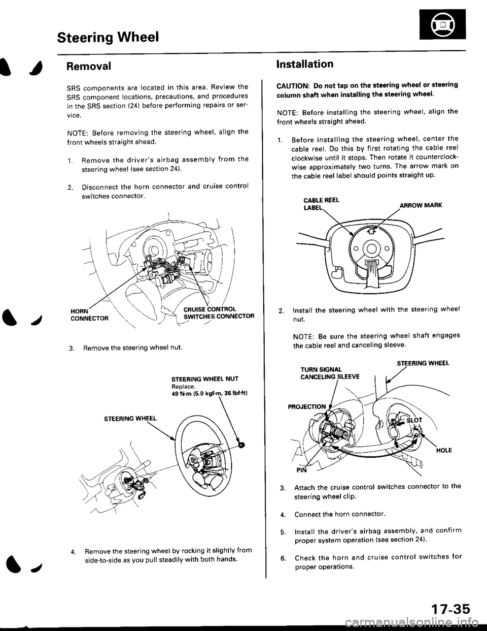
NOTE: Before removing the steering wheel. align the
front wheels straight ahead.
1. Remove the driver's airbag assembly from the
steering wheel (see section 24)
2. Disconnect the horn connector and cruise control
switches connector.
CRUISESWITCHES CONNECTOR
3. Remove the steering wheel nut
STEERING WHEEL NUT
Replace.
Remove the steering wheel by rocking it slightly from
side-to-side as you pull steadily with both hands.
ag N.m {5.0 kgt rn, 36lbfft)
1.,
17-35
lnstallation
CAUTION: Do not tap on the steering wheel or steering
column shaft when installing the stsering wheel.
NOTE: Before installing the steering wheel, align the
front wheels straight ahead.
1. Before installing the steering wheel, center the
cable reel, Do this by first rotating the cable reel
clockwise until it stops. Then rotate it counterclock-
wise approximately two turns The arrow mark on
the cable reel label should points straight up.
Install the steering wheel with the steering wheel
nut.
NOTE: Be sure the steering wheel shaft engages
the cable reel and canceling sleeve.
Attach the cruise control switches connector io the
steering wheel cliP,
Connect the horn connector.
Install the driver's airbag assembly, and confirm
proper system operation (see section 24).
Check the horn and cruise control switches for
proper operatrons.
CAELE REEL
Page 1093 of 2189
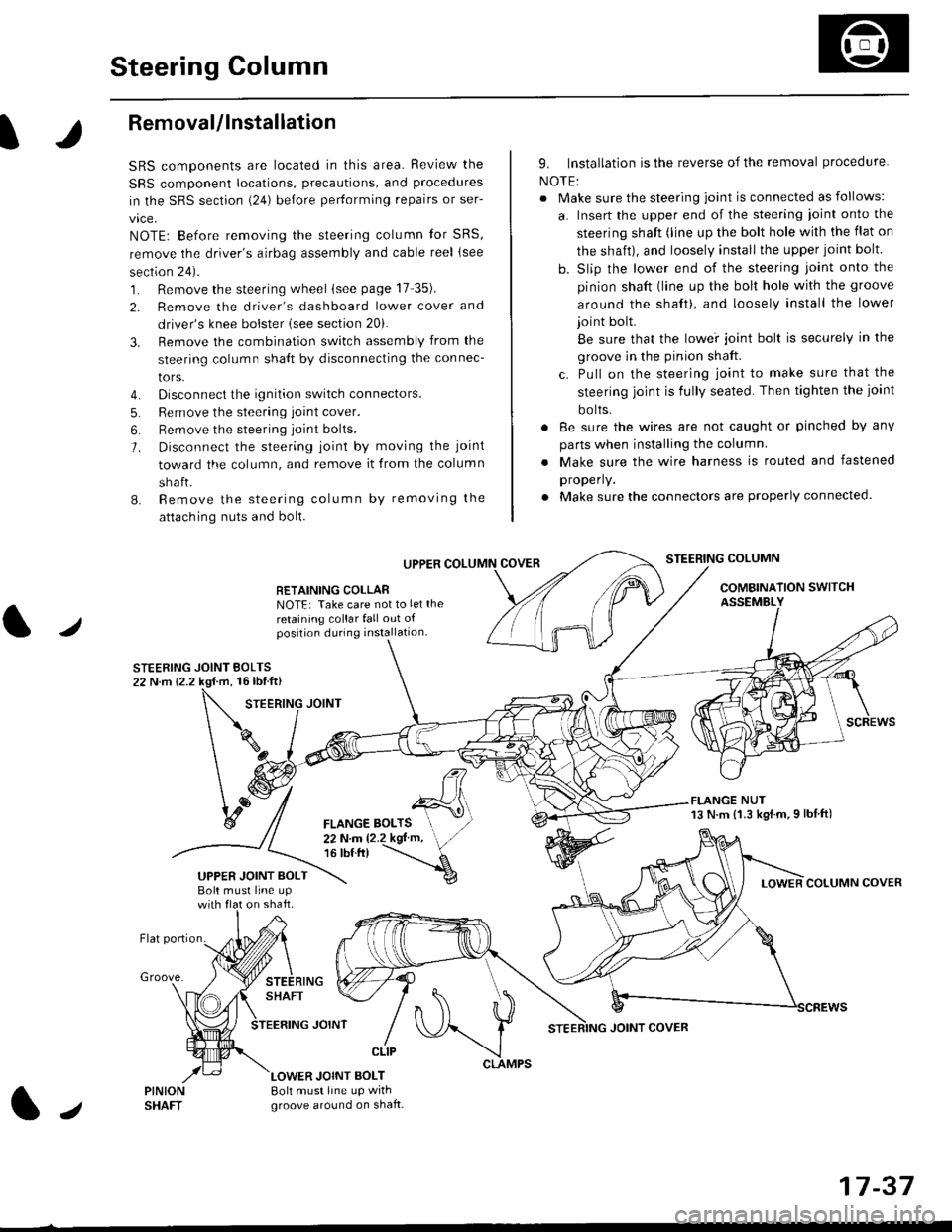
Steering Column
I
Removal/lnstallation
SRS components are located in this area. Review the
SRS component locations, precautions, and proceclures
in the SRS sectron (24) before pertorming repairs or ser-
vice.
NOTE: Before removing the steering column for SRS,
remove the driver's airbag assembly and cable reel lsee
section 24).
1. Remove the steering wheel (see page 17 35).
2. Remove the driver's dashboard lower cover and
driver's knee bolster (see section 20).
3. Remove the combination switch assembly from the
steering column sha{t by disconnecting the connec-
tors.
4. Disconnect the ignition switch connectors.
5. Remove the steering joint cover.
6. Bemove the steering joint bolls.
7. Disconnect the steering ioint by moving the joint
toward the column, and remove it from the column
shaft.
8. Remove the steering column by removing the
attaching nuts and bolt.
UPPER
RETAINING COLLABNOTE: Take care not to let the
retaining collar fall out ofposition during installation.
STEERING JOINT BOLTS22 N.m {2.2 kgf.m, 16lbtft}
9. Installation is the reverse of the removal procedure
NOTE:
. Make sure the steering joint is connected as follows:
a. Insert the upper end of the steering ioint onto the
steering shaft (line up the bolt hole with the flat on
the shait), and loosely install the upper joint bolt.
b. Slip the lower end of the steering joint onto the
pinion shaft (line up the bolt hole with the groove
around the shaft), and loosely install the lower
joint bolt.
Be sure that the lowei joint bolt is securely in the
groove in the pinion shaft.
c. Pull on the steering joint to make sure that the
steering joint js fully seated. Then tighten the ioint
bolts.
. 8e sure the wires are not caught or pinched by any
parts when installing the column
. Make sure the wire harness is routed and fastened
properly.
. Make sure the connectors are properly connected.
STEERING COLUMN
COMBINATION SWITCHASSEMBLY
FLANGE NUT13 N.m {1.3 kgl.m.9 lbf ft)
COLUMN COVER
FLANGE BOLTS22Nm12.2kgl'm,16 tbt.tr)
UPPER JOINT BOLTBolt musl line upon shaft.
Groove.
LOWER JOINT BOLT8oh must line up wrthgroove around on shaft.
CLIP
J
JOINT COVER
17-37
Page 1097 of 2189
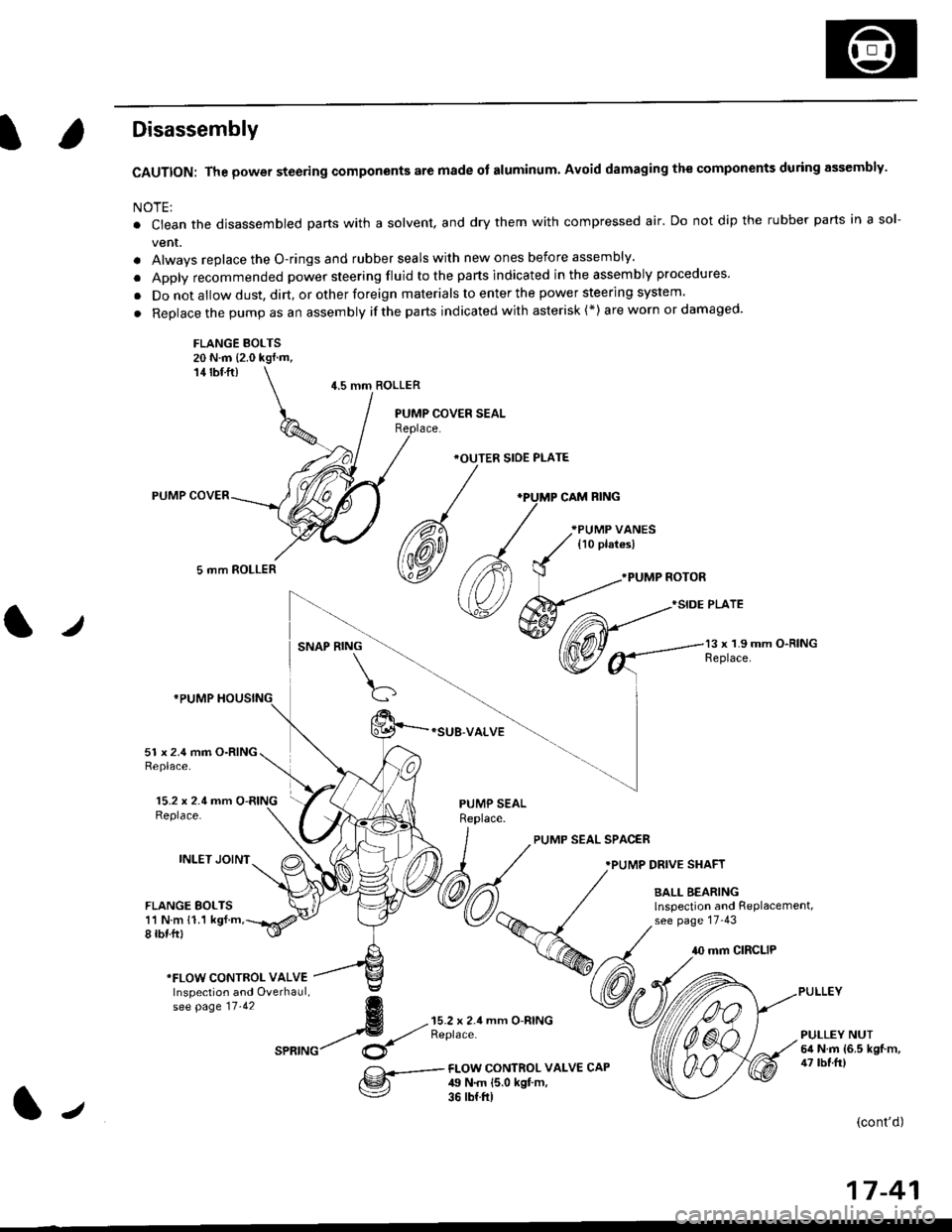
Disassembly
CAUTION: The power steering components are made of aluminum. Avoid damaging the components during assembly.
NOTE:
. Ctean the disassembled parts with a solvent, and dry them with compressed air. Do not dip the rubber parts in a sol-
vent.
. Alwavs replace the O-rings and rubber seals with new ones before assembly.
. Apply recommended power steering fluid to the parts indicated in the assembly procedures'
. Do not allow dust, dirt, or other foreign materials to enter the power steering system.
. Replace the pump as an assembly ifthe parts indicated with asterisk (*) are worn or damaged'
FLANGE BOLTS20 N.m {2.0 kgf.m,14 rbf ft)
5 mm ROLLER
4.5 mm ROLLER
*OUTER SIOE PLATE
*SUB-VALVE
.PUMP NOTOR
}SIDE PLATE
l,/SNAP RING13 x 1.9 mm O-RINGReplace.
15.2 x 2.4 mm O-RINGReplace.
INLET JOINT
51 x 2.4 mm O-RINGReplace.
FLANGE BOLTS11 N m 11.1 kgf.m,8 rbf.ftl
PUMP SEALReplace.
PUMP SEAL SPAC€R
.PUMP DRIVE SHAFT
BALL BEARINGlnspection and RePlacement,see page 17-43
10 mm CIRCLIP
*FLOW CONTROI- VALVEInspection and Overhaul,se[ pase tt.tz g
4 --{;'rX!;'seatuc/ $
mm O-RINGPULLEY NUT6il N.m {6.5 kgf.m,47 tbf.frlFI-OW CONTROL VALV€ CAP49 N.m {5.0 kgt m,36 rb{.ft)
(cont'd)
17-41
J