1996 HONDA CIVIC Drive shaft
[x] Cancel search: Drive shaftPage 1098 of 2189
Power Steering Pump
Disassembly (cont'dl
2.
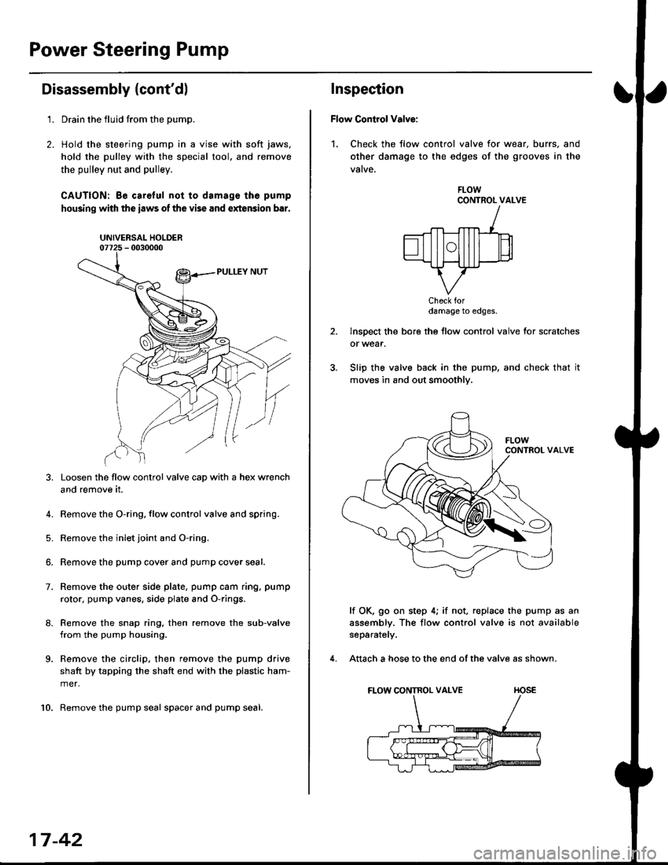
't.Drain the fluid from the pump.
Hold the steering pump in a vise with soft jaws,
hold the pulley with the special tool, and remove
the pulley nut and pulley.
CAUTION: Be careful not to damage the pump
housing with the iaws of the vise and extension bar.
UNIVERSAL HOLDER
Loosen the flow control valve cap with a hex wrench
and remove it.
4. Remove the O-ring, flow control valve and spring.
5. Remove the inlet joint and O-ring.
6. Remove the pump cover and pump cover seal.
7. Remove the outer side plate, pump cam ring, pump
rotor, pump vanes, side plate and O-rings.
8. Remove the snap ring, then remove the sub-valve
from the pump housing.
9. Remove the circlip, then remove the pump drive
shaft by tapping the shaft end with the plastic ham-
mer.
10. Remove the pump seal spacer and pump seal.
17-42
Inspection
Flow Control Valve:
1. Check the tlow control valve for wear. burrs, and
other damage to the edges of the grooves in the
vatve,
FLOWCONTROL VALVE
Check fordamage to edges.
Inspect the bore the flow control valve for scratches
or wear.
Slip the valve back in the pump, and check that it
moves in and out smoothly.
lf OK, go on step 4; if not, replace the pump as an
assembly. The flow control valve is not available
separately.
Attach a hose to the end of the valve as shown.
FLOW CONTROL VALVE TIOSE
4.
Page 1100 of 2189
Power Steering Pump
Reassembly
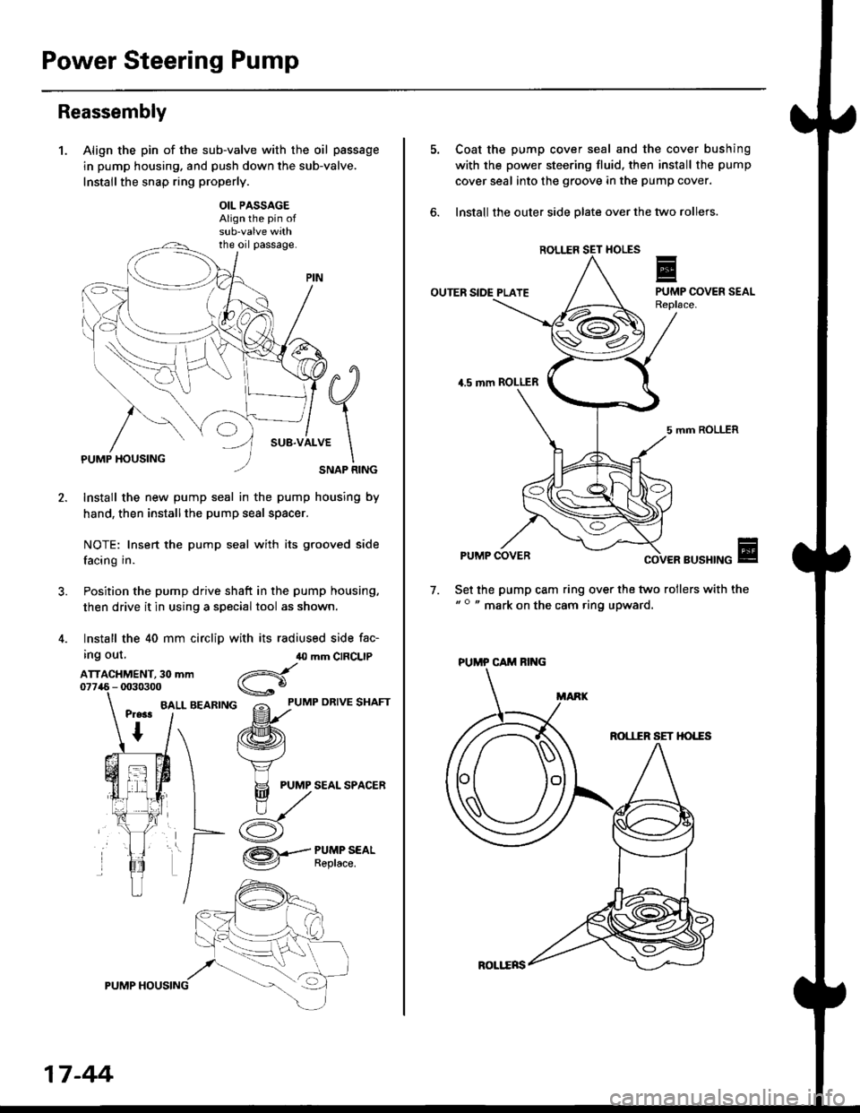
1.Align the pin of the sub-valve with the oil passage
in pump housing. and push down the sub-valve.
Installthe snap ring properly.
OIL PASSAGEAlign the pin of
the oil passage.
PUMP HOUSINGSNAP RING
Install the new pump seal in the pump housing by
hand, then installthe pump seal spacer.
NOTE: Insert the pump seal with its grooved side
facing in.
Position the pump drive shaft in the pump housing,
then drive it in using a special tool as shown.
Install the 40 mm circlip with its radiused side fac-
ing out,
ATTACHMENT, 30 mm
BALL BEARING
40 mm CIRCLIP
d
gf'uMP oRrvE sHAFr
/ffi\
f.\'vj
H PUMP SEAL SPACER
n,/
/:K
/ZA\.-- PUMP SEAL
V Reptace.
17 -44
ROLl.ERS
Coat the pump cover seal and the cover bushing
with the power steering fluid, then install the pump
cover seal into the groove in the pump cover.
lnstall the outer side olate over the two rollers.
ROL1IR
OUTER SIDE PLATE
4.5 mm ROLLER
5 mm ROLLER
PUMP COVERBUSHING
Set the pump cam ring over the two rollers with the" o " mark on the cam ring upward.
7.
ROI,IIR SET HO'"ES
PUMP CAM RING
Page 1113 of 2189
I
14.
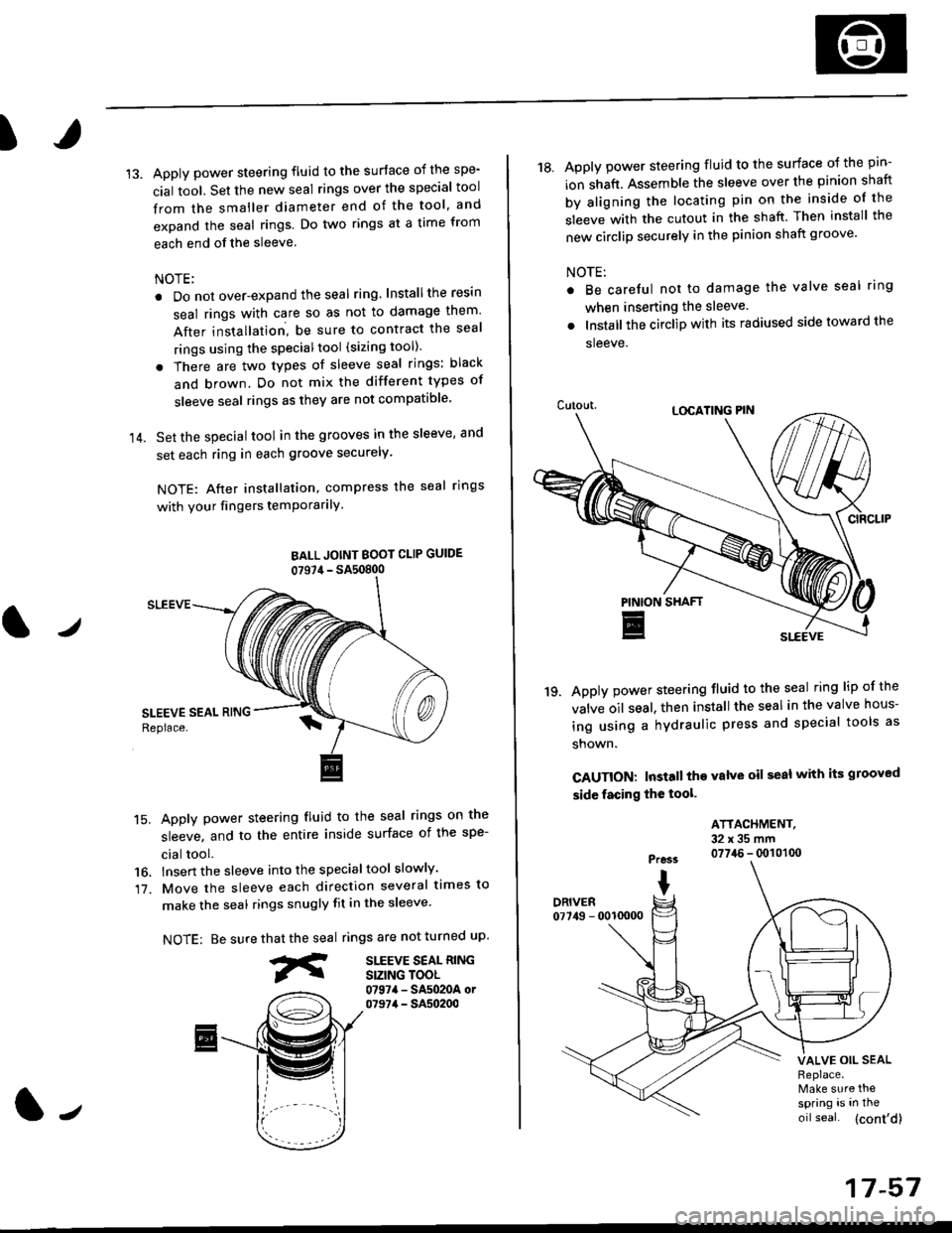
Apply power steering fluid to the surface of the spe-
cial tool. Set the new seal rings over the special tool
from the smaller diameter end of the tool, and
expand the seal rings. Do two rings at a time from
each end of the sleeve.
NOTE;
. Do not over-expand the seal ring. Installthe resin
seal rings with care so as not to damage them'
After installation, be sure to contract the seal
rings using the specialtool (sizing tool).
. There are two types of sleeve seal rings: black
and brown. Do not mix the different types of
sleeve seal rings as they are not compatible
Set the special tool in the grooves in the sleeve, and
set each ring in each groove securely.
NOTE: After installation, compress the seal rings
with your fingers temPorarilY
BALL JOINT BOOI CLIP GUIDE
07S7,1- SA50800
SLEEVE
15. Apply power steering fluid to the seal rings on the
sleeve, and to the entire inside surface of the spe-
cial tool.
16. lnsert the sleeve into the specialtool slowly'
17. Move the sleeve each direction several times to
make the seal rings snugly fit in the sleeve'
NOTE: Be surerings are not turned uP.
SITEVE SEAL RINGSIZING TOOL0797a - SA5020A or07974 - SA50200
that the seal
fr
J
17-57
18. Apply power steering fluid to the surface o{ the pin-
ion shaft. Assemble the sleeve over the pinion shaft
by aligning the locating pin on the inside of the
sleeve with the cutout in the shaft. Then install the
new circlip securely in the pinion shaft groove'
NOTE:
Be careful not to damage the valve seal ring
when inserting the sleeve.
Installthe circlip with its radiused side toward the
sleeve.
Apply power steering fluid to the seal ring lip of the
valve oil seal. then install the seal in the valve hous-
ing using a hydraulic press and special tools as
shown.
CAUTION: Install the valve oil seal with its grooved
side facing the tool.
'19.
ATTACHMENT.32x35mm0774.6 - q)101(x)Pre3s
IDRIVER07749 - 0010000
VALVE OIL SEALReplace.Make sure thespring is in the
oil seal. (cont'd)
Page 1114 of 2189
Steering Gearbox
Reassembly (cont'd)
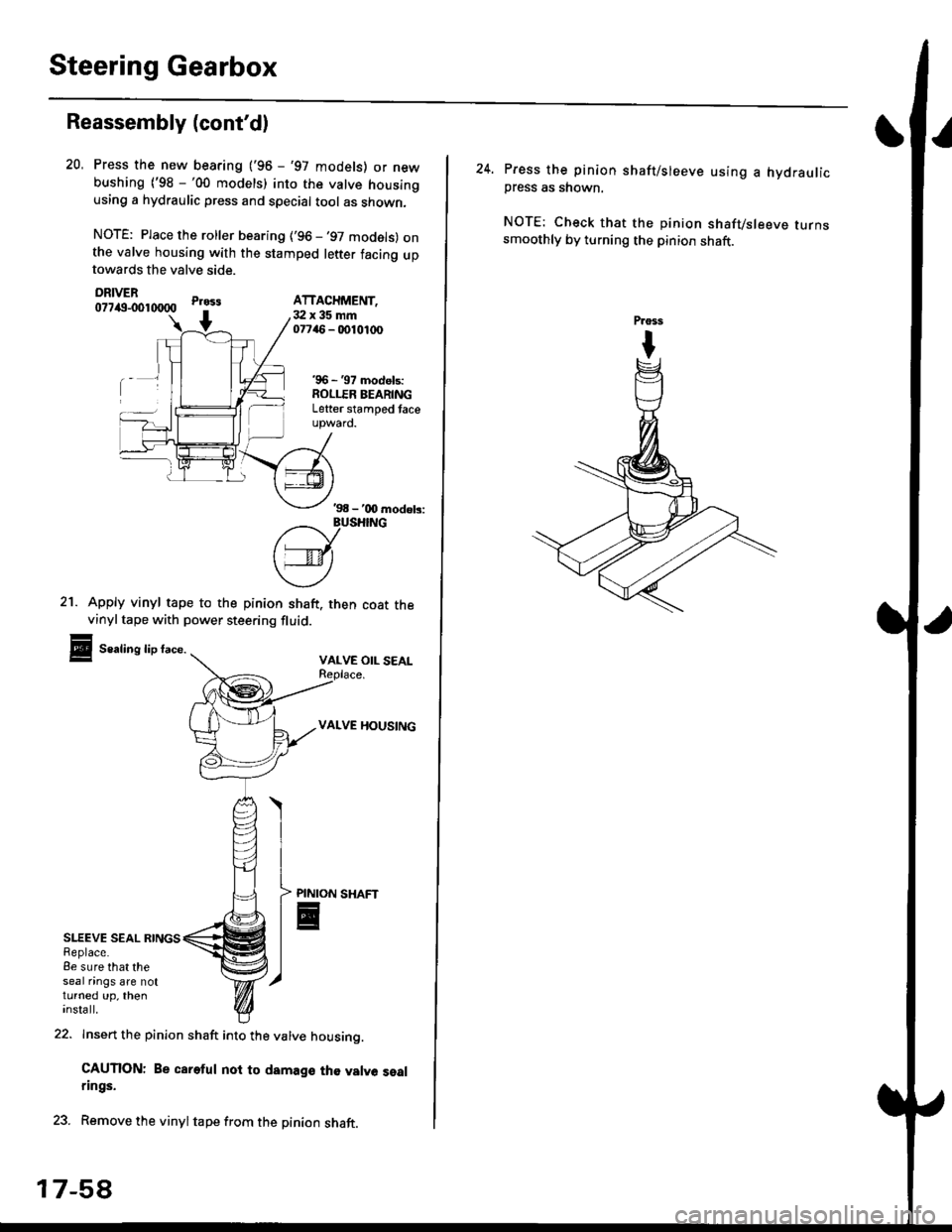
SLEEVE SEAL RINGSReplace.8e sure that theseal nngs are notturned up, theninsta ll.
21. Apply vinyl tape to the pinion shaft. then coat thevinyltape with power steering fluid.
Sealing lip face.VALVE OIL SEAL
VALVE HOUSING
Press the new bearing ('96 - '97 models) or newbushing ('98 -'00 models) into the valve housingusing a hydraulic press and special tool as shown,
NOTE: Place the roller bearing ('96 -'97 models) onthe valve housing with the stamped letter facing uptowards the valve side.
DRIVER077itg-001tXlOO
22. Insert the pinion shaft into the valve housino.
CAUTION: Be careful noi to damage th€ valve sealrings.
23. Remove the vinyltape from the pinion shaft.
20.
Pr033
+3:Ix35mm07746 - 0010,t(x)
'96 - '97 models:ROLLER BEARINGLetter stamped taceupward.
ATTACHMENT,
'98 - '00 modob:
?/_vusHrNG
['---v-lt
\4)
PINION
E
17-5A
24. Press the pinion shaft/sleeve using a hydraulicpress as shown.
NOTE: Check that the pinion shafvsleeve turnssmoothly by turning the pinion shaft.
Page 1126 of 2189
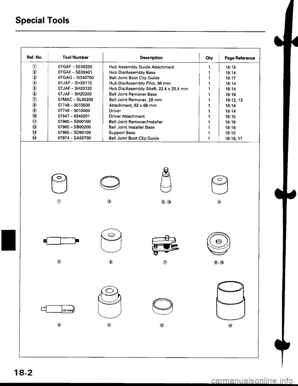
Special Tools
Ref. No. Tool NumborDescriptionOty Page Reteronc€
o
€)
@
\9
o
@aa\
@
o
@
@
@
07GAF - SE00200
07GAF - SE00401
07GAG - SD40700
07JAF - SH201 l0
07JAF - SH20120
07JAF - SH20200
07MAC - S100200
07746 - 0010500
07749 - 0010000
07947 - 6340201
07965 - SB00100
07965 - 5800200
07965 - SD90100
07974 - SA50700
Hub Assembly Guide Attachment
Hub DivAssembly Base
Ball Joint Boot Clip Guide
Hub Dis/Assembly Pilot, 38 mm
Hub Dis/Assembly Shaft,22.4 x25.4 mm
Ball Joint Remover Base
Ball Joint Remover,2S mm
Attachment, 62 x 68 mm
Driver
Driver Attachment
Eall Joint Remover/lnstaller
Ball Joint Installer Base
Support Base
Ball Joint Boot Clip Guide
,|
1
1
1
1
1
1
1
1
1
1
1
I
1
td- tc
18- 14
18-17
18- 14
18- 14
18-16
18-12, 13
18-14
18- 14
18- 15
18- 16
18- 16
18-15
18-16, 17
o@@.@@
@
o@
1a-2
Page 1134 of 2189
Front Suspension
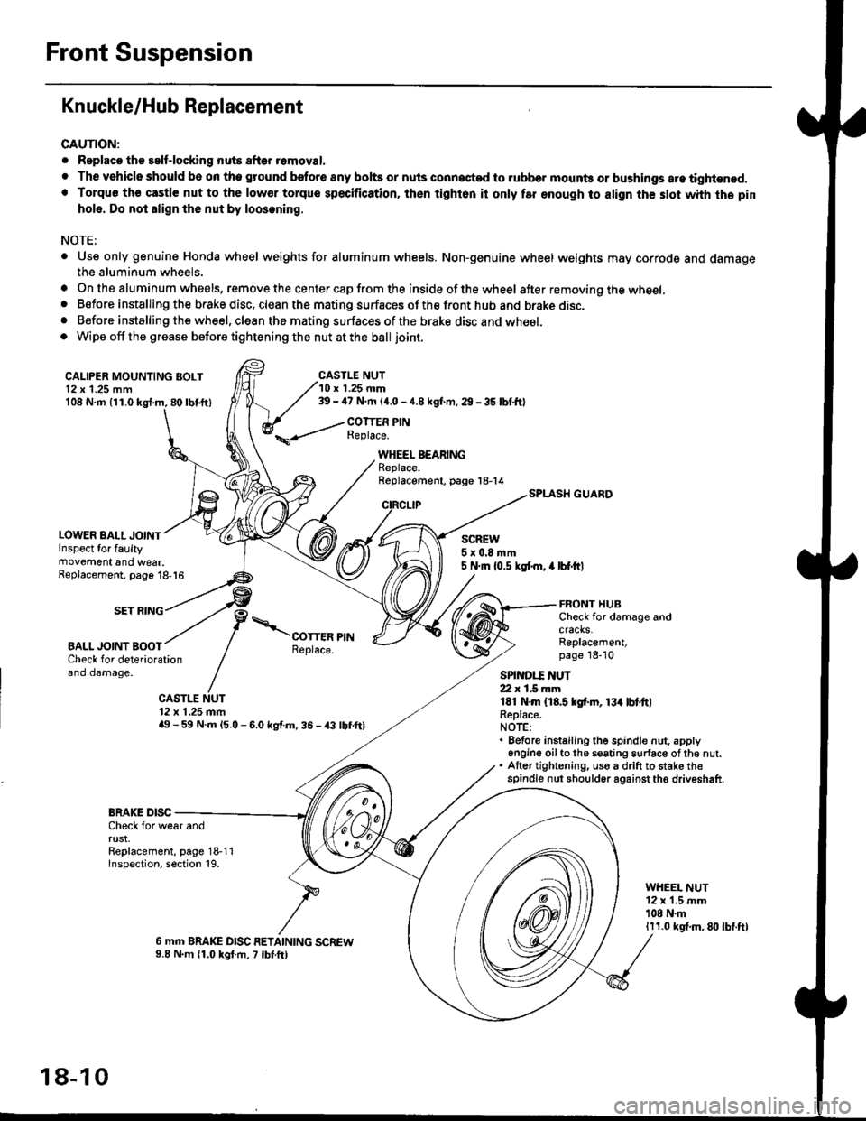
Knuckle/Hub Replacement
CAUTION:
. Replaco tho salf-locking nuts after romoval.
. The vehiclo should be on tho ground bsfore any bohs or nuls connected to rubber mounb or bushings are tightened.. Torqu€ th€ castle nut to the lowor torque specification, ihen tighton it only far enough to align th€ slot whh the pin
hole. Do not align the nut by loosening.
NOTE:
. Use only genuine Honda wheel weights for aluminum wheels. Non-genuine wheel weights may corrode and damagethe aluminum wheels.
. On the aluminum wheels, remove the center cap from the inside of the wheel after removing the wheel,. Before installing the brake disc, clean the mating surfaces of the front hub and brake disc,. Before installing the wheel, clean the mating surfaces of the brake disc and wheel.o Wipe off the grease before tightening the nut at the ball joint.
CALIPER MOUNTING BOLT12 x 1.25 mm108 N.m {11.0 kgl.m, 80lbf.ft)
LOWER BALL JOINTInspect for faultymovement and wear.
CASTLE NUT10 r 1.25 mm39 - ia7 N.m (4.0 - 4.8 kgf.m, 29 - 35 lbf,ftl
COTTER PINReplace.
WHEEL BEARINGReplace.Replacement, page 18-14
CIRCLIP
SCREW5x0.8mm5 N.m {0.5 ksl.m, 4 lbf.ftlReplacement, page 18-16
SET RING
BALL JOINT BOOT
FRONT HUBCheck for damage andcracks.Replacement,page 18-10Check for deteriorationand damage.
CASTLE NUT12 x 1.25 mm49 - 59 N.m l5.O - 6.0 kg{.m. 36 - /(} lbf,ftl
SPINDI.T ]{UT22 r 1.5 mmlEl N.m {18.5 kgf.rn, 13{ lbl.ttlReplace.NOTE:. Before instelling the spindle nut. apply6n9ine oilto th6 seating surface ofthe nut.. Atter tightening, uso a drift to stake thespindle nut should6r against the driveshaft.
BRAKE DISCCheck for wear andrust.Replacement, page 18-11lnspection, section 19.
WHEEL NUT12 x 1.5 mm'108 N.m1r1.0 kgf.m, 8lt lbf.ft)
6 mm BRAKE DISC RETAINING SCREW9.8 N.m 11.0 kgf.m, 7 lbtft)
18-10
Page 1135 of 2189
)
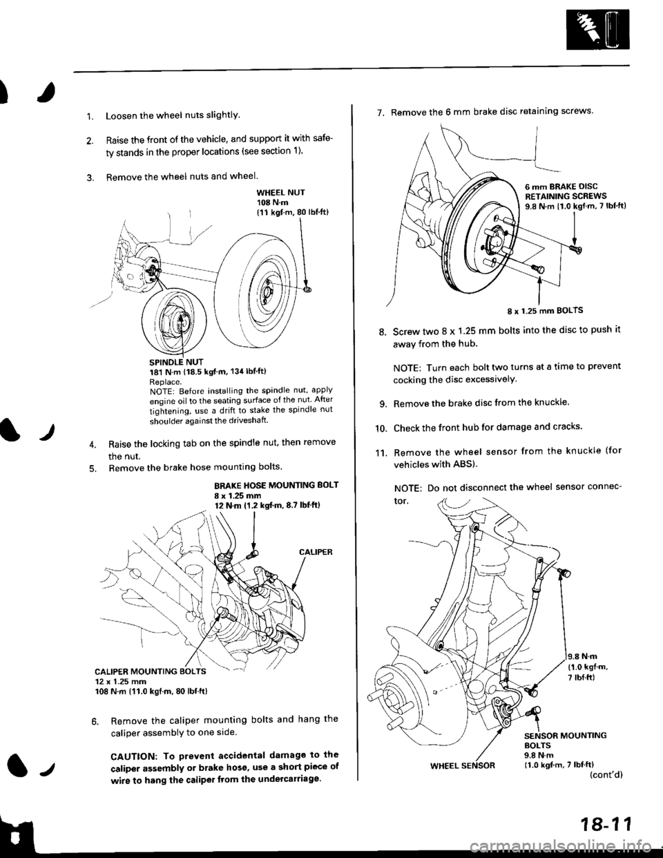
1.Loosen the wheel nuts slightlY.
Raise the front of the vehicle, and support it with safe-
ty stands in the proper locations (see section 1).
Remove the wheel nuts and wheel.3.
l)
WHEEL NUT'108 N.m
18'l N.m 118.5 kgf m, 134lblfti
Replace.NOTEI Before installing the spandle nut, apply
engine oil to the seating surface of the nut After
tightening, use a drift to stake the spindle nut
shoulder againsl the driveshaft
Raise the locking tab on the spindle nut, then remove
the nut.
Remove the brake hose mounting bolts.
BRAKE HOSE MOUNTING BOLT
I x 1.25 mm12 N.m (1,2 kgtm,8,7 lbf'ftl
6. Remove the caliper mounting bolts and hang the
caliper assembiy to one side
CAUTTON: To prevent accidental damage to the
caliper assembly or brake hoso' use a short piece of
wire to hang the caliPer tlom lhe undelcarriage.
{11 kgf m, 80 lbl.ft)
CALIPER MOUNTING BOLTS12 x 1.25 mm108 N.m {'11.0 kgtm, 80 lbt.ft)
7. Remove the 6 mm brake disc retaining screws.
8.
I x 1.25 mm BOLTS
Screw two 8 x 1.25 mm bolts into the disc to push it
away from the hub,
NOTE: Turn each bolt two turns at a tame to prevent
cocking the disc excessivelY.
Remove the brake disc from the knuckle.
Check the front hub for damage and cracks.
Remove the wheel sensor from the knuckle (for
vehicles with ABS).
NOTE: Do not disconnect the wheel sensor connec-
tor.
N.m
6 mm BRAKE OISCRETAINING SCREWS9.8 N.m t1.0 kgf.m, 7 lbf'ft)
{'1.0 kgf m,
7 tbf.ft)
10.
11.
MOUNTING
WHEEL
BOLTS9.8 N.m11.0 kgf,m, 7 lbf'ft)(cont'd)
Page 1137 of 2189
)
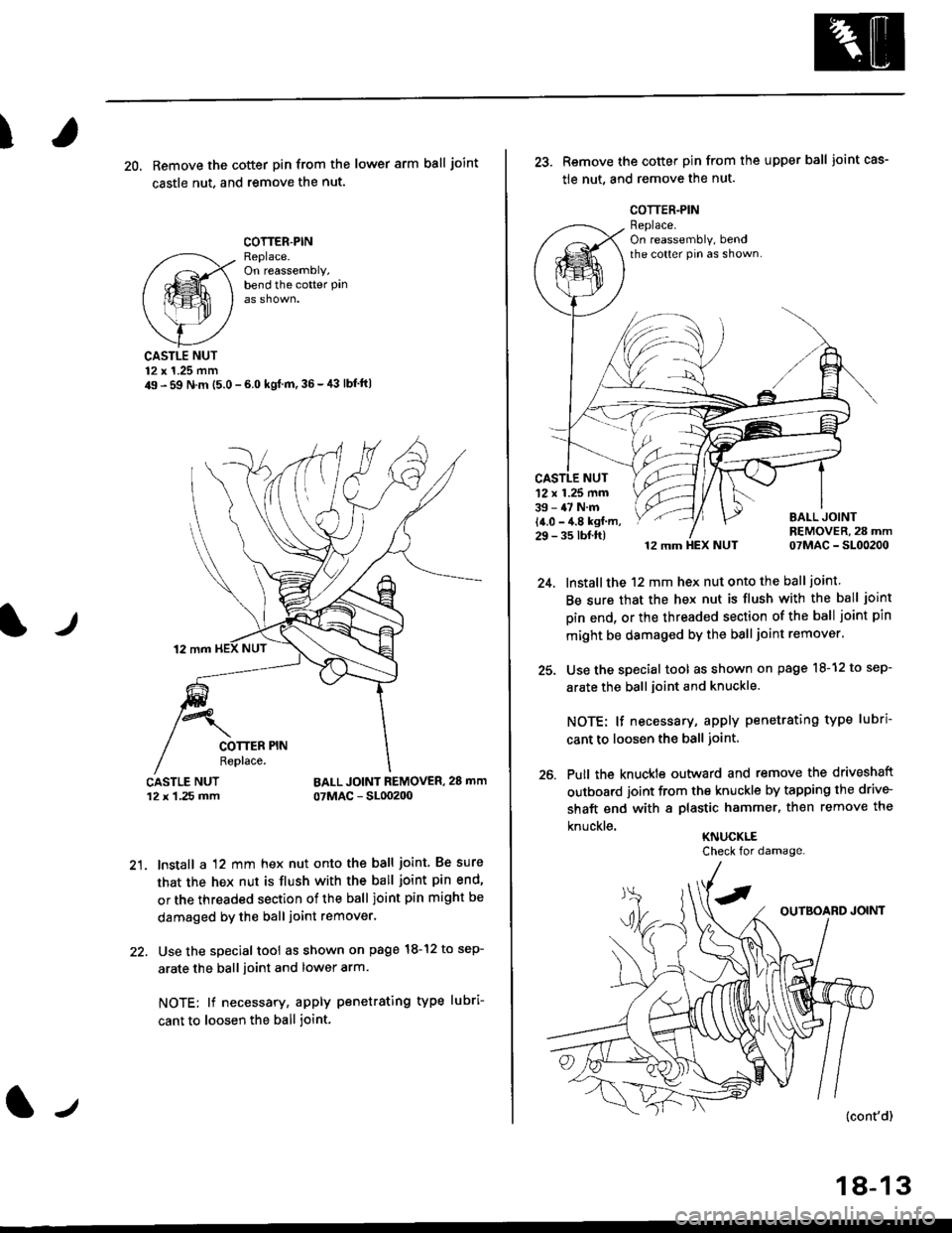
20, Remove the cotter pin from the lower arm ball joint
castle nut. and remove the nut.
COTTER.PINReplace.On reassembly,bend the cotter Pan
lr
CASTLE NUT12 x 1.25 mm49 - 59 N.m (5.0 - 6.0 kgl m,36-,13 lbf'ft|
BALL JOINT REMOVER, 28 mm
07MAC - SL00200
21. lnstall a 12 mm hex nut onto the ball joint. Be sure
that the hex nut is flush with the ball joint pin end'
or the threaded section of the ball joint pin might be
damaged by the ball joint remover.
22. Use the special tool as shown on page l8-12 to sep-
arate the ball ioint and lower arm.
NOTE; lf necessary, apply penetrating type lubri-
cant to loosen the ball joint.
lJ
18-13
25.
26.
Remove the cotter pin from the upper ball joint cas-
tle nut, and remove the nut.
12 mm HEX NUT 07MAC - SL00200
lnstall the 12 mm hex nut onto the ball joint
Be sure that the hex nut is flush with the ball joint
pin end, or the threaded section of the ball joint pin
mlght be damaged by the ball joint remover'
Use the special tool as shown on page l8-12 to sep-
arate the ball joint and knuckle.
NOTE: lf necessary, apply penetrating type lubri
cant to loosen the ball joint.
Putl the knuckte outward and remove the driveshaft
outboard joint from the knuckle by tapping the drive-
shaft end with a plastic hammer, then remove the
knuckle.KNUCKLE
'12 x 1.25 mm39 - 47 N.m
14.0 - 4.8 kgf m,29 - 35 tbf.ft)
Check for damage.