1996 HONDA CIVIC piston torque
[x] Cancel search: piston torquePage 123 of 2189

Valve Clearance
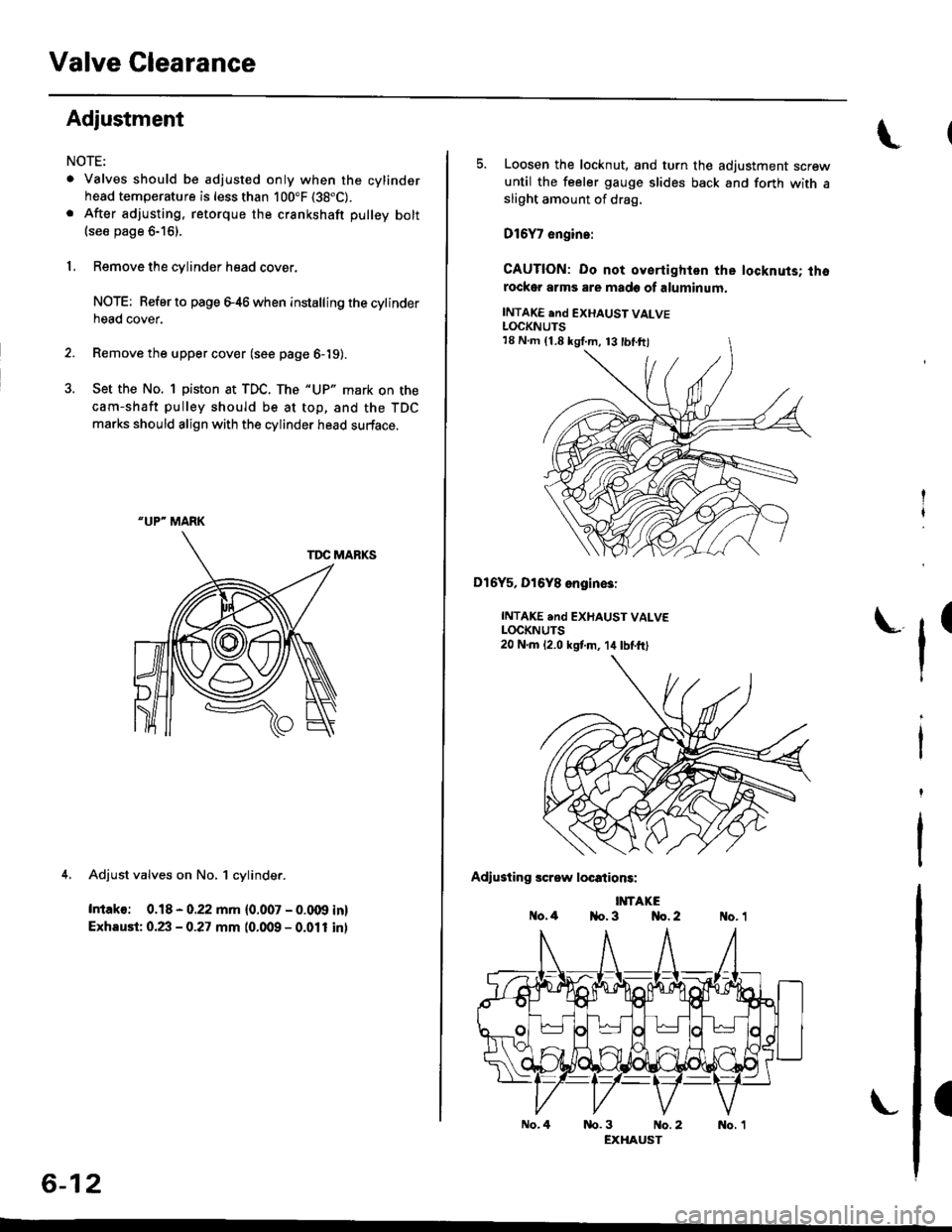
Adjustment
NOTE:
. Valves should be adjusted only when the cylindsrhead temperature is less than 100"F (38"C).
. After adjusting, retorque the crankshaft pulley bolt(see page 6-16).
1, Remove the cylinder head cover.
NOTE; Refer to page e46 when installing the cytinderhead cover.
2. Remove the upper cover (see page 6-19).
3. Set the No. 1 piston at TDC. The "UP" mark on the
cam-shaft pulley should be at top, and the TDC
marks should align with the cylinder head surface.
TDC MARKS
4. Adjust valves on No, 1 cylinder.
Intako: 0.18 - 0.22 mm {0.007 - 0.009 in}
Exhaust: 0.23 - 0.27 mm (0.009 - 0.011 inl
"UP" MARK
6-12
No.4
5. Loosen the locknut, and turn the adjustment screwuntil the feeler gauge slides back and forth with asliOht amount of drag,
D16Y7 engin.:
CAUTION: Do not oyertighlen the locknuts; thorockor arms are made of aluminum.
INTAKE end EXHAUST VALVELOCKNUTS
Dl6Y5, Dl6Y8 engin€3:
INTAKE .nd EXHAUST VALVELOCKNUTS20 N.m 12.0 kstm, 14lbtft)
Adiusting screw locations:
IMTAKEo.4 1{o. 3 No. 2
tr'
(
nb.3 No.2 No. 1EXHAUST
18 N.m (1.8 kgI.m, 13 tbl.ftl
Page 129 of 2189

Timing Belt
Inspection
1.
2.
3.
Remove the cylinder head cover.
. Refer to page 6 46 when installing.
Remove the upper cover (see page 6 19).
Inspect the timing belt for cracks and oil or coolantsoakrng.
NOTE:
. Replace the belt if oil or coolant soaKeo.. Remove any oil or solvent that gets on the belt.
Rotate pulleyand inspect belt.
After inspecting, retorque the crankshaft pullev bolt{see page 6- 16).
o- I6
Tension Adjustment
CAUTION: lt*ays aa;j"t the timing bett rension withthe engine cold.
NOTE:
. The tensioner is spring loaded to apply tension to thebelt automatically after making the following adjustment.
. Always rotate the crankshaft counterclockwise whenviewed from the pulley side. Rotating it clockwisemay result in improper adjustment of the belt ten-sion.
. lnspect the timing belt before adjusting the belt ten-ston.
1.Remove the cylinder head cover.
. Refer to page 6,46 when installing.
Remove the upper cover (see page 6,'19).
Rotate the crankshaft five or six revolutions to setthe belt.
Set the No. 'l piston at TDC (see page 6-21).
Loosen the adjusting bolt 180'.
2.
3.
4.
5.
\I
ADJUSTING BOLT44 N.m {4.5 kgt m,33 rbf.ft)
7.
8.
Rotate the crankshaft counterclockwise three teethon the camshaft pulley.
Tighten the adjusting bolt.
After inspecting, retorque the crankshaft pulley bolt(see page 6-16).
Page 167 of 2189

Valve Glearance
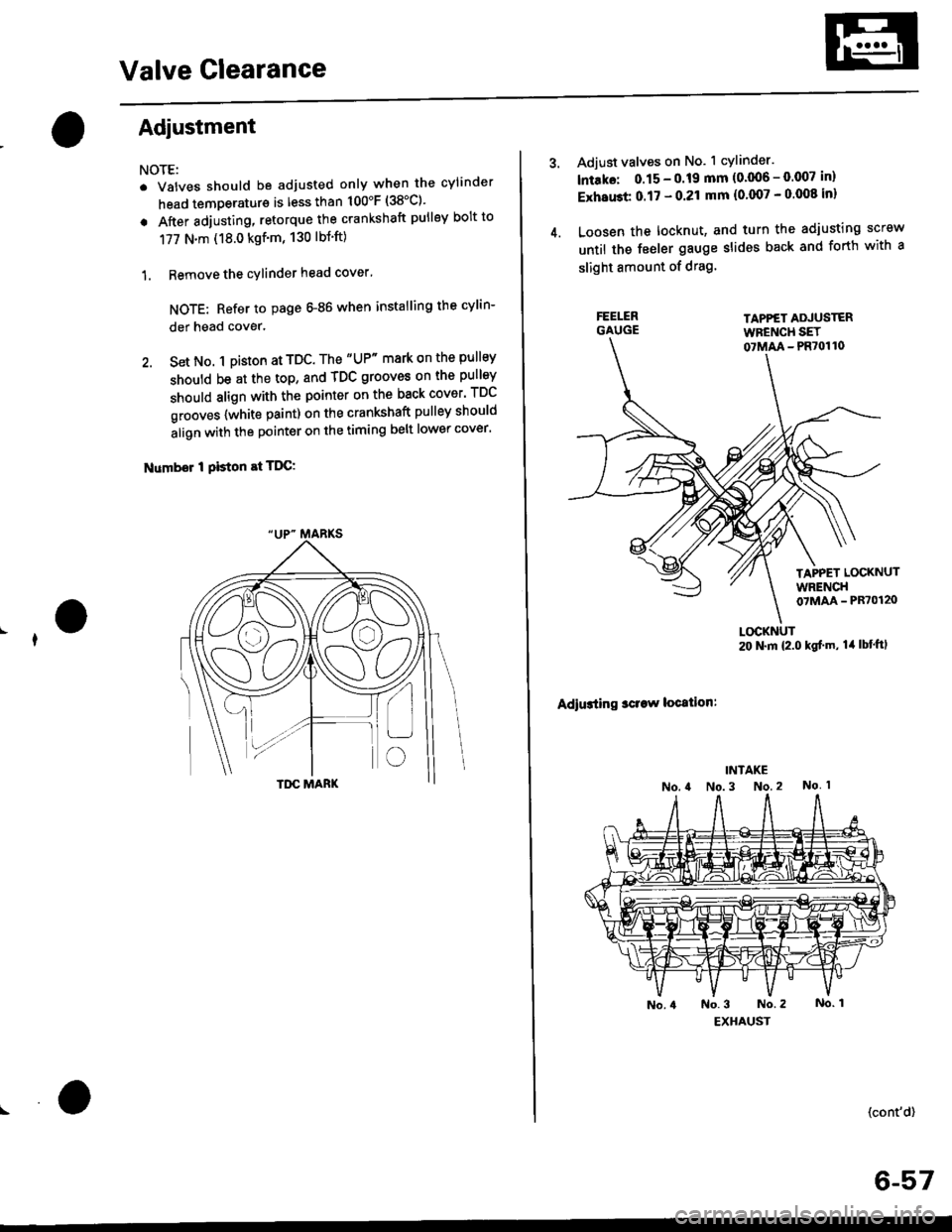
Adjustment
NOTE:
. Valves should be adjusted only when the cylinder
head temperaturs is less than 100'F (38'C)'
. After adjusting, retorque the crankshaft pulley bolt to
177 N.m (18.0 kgf'm, 130 lbt'ft)
1. Remove the cylinder head cover'
NOTE: Refer to page G86 when installing the cylin-
der head cover.
2. Set No. 1 pi$on at TDC. The "UP" mark on the pullsy
should be at the top, and TDC grooves on the pulley
should align with the pointer on the back cover' TDC
grooves {white paint) on the crankshaft pulley should
align with the pointer on the timing belt lower cover'
Number I Piston at TDC:
4.
Adjust valves on No. 1 cylinder.
lntako: 0.15 - 0.19 mm {0'006 - 0.007 in)
ExhaGt 0.17 - 0.21 mm {0'007 - 0 008 inl
Loosen the locknut, and turn the adjusting screw
until the feeler gauge slides back and forth with a
slight amount of drag.
TAPPET ADJUSTERWFENCH SET07MM - PR70110
TAPPET LOCKNUTWRENCH07MAA - PR70120
Adiusting sclaw location:
LOCKNUT20 N.m {2.0 kgf'm, lil lbt'ftl
(cont'd)
6-57
Page 171 of 2189

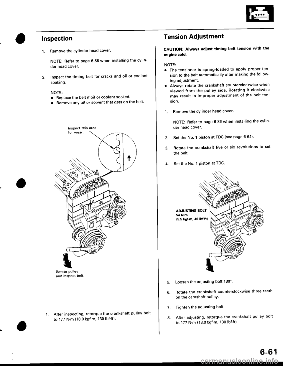
Inspection
Remove the cylinder head cover.
NOTE: Refer to page 6-86 when installing the cylin-
der head cover.
Inspect the timing belt for cracks and oil or coolant
soakrng.
NOTE:
. Replace the belt if oil or coola nt soaked.
. Remove any oil or solvent that gets on the belt'
I
Rotate PUlleYand inspect belt-
After inspecting, retorque the crankshaft pul
to 177 N.m (18.0 kgf'm, 130 lbf'ft)
'L
lnspect thrs area
Tension Adiustment
CAUTION: Always adiust timing belt tension with the
engine cold.
NOTE:
. The tensioner is spring-loaded to apply proper ten
sion to the belt automatically after making the follow-
ing adjustment.
. Always rotate the crankshaft counterclockwise when
viewed from the pulley side. Rotating it clockw'se
may result in improper adjustment of the belt ten-
sion.
1, Remove the cylinder head cover.
NOTE; Refer to page 6-86 when installing the cylin-
der head cover.
2. Set the No. 1 piston at TDC (see page 6-64)
3. Rotate the crankshaft live or six revolutions to set
the belt.
4. Set the No. 1 Piston at TDC
ADJUSTING BOLT
54 N.m(5.5 kgt.m, a0 lbtftl
5.
7.
8.
Loosen the adjusting bolt 180'.
Rotate the crankshaft counterclockwise three teeth
on the camshaft PulleY.
Tighten the adjusting bolt.
After adjusting, retorque the crankshaft pulley bolt
to 177 N.m (18.0 kgf'm, 130 lbnft)
ley bolt
6-61
Page 194 of 2189

I
Cylinder Head
Installation
lnstall the cylinder head in the reverse order of removal:
NOTE:
. Always use a new head and manifold gasket.. The cylinder head gasket is a metal gasket, Take carenot to bend it.
. Rotate the crankshaft, set the No. 1 piston at TDC (seepage 6-63).
. Do not use the middle cover and lower cover forstorang removed items.. Clean the middle cover and lower cover before instal_lation.
o Replace any washers that are damaged or deteriorated.
1. Install the cylinder head gasket, dowel pins and thehead oil control orifice on the cylinder head.
NOTE: Clean the oil control orifice when installing.
DOWEL PIN
6-84
2, Tighten the cylinder head bolts in two steps. In thefirst step, tighten all bolts in sequence to about 29N.m (3.0 kgf.m, 22 tbf.ftl. ln the final step, tighten inthe same sequence to 83 N.m (8.S kgf.m,6t lbf.ft).
NOTE:
. Apply clean engine oil to the bolt threads andunder the bolt head.. We recommend using a beam-type torquewrench. When using a preset-type torque wrench,be sure to tighten slowly and not to overtighten.. lf a bolt makes any noise while you are torquing it,loosen the bolt, and retighten it from the 1st step.
CYLINDER HEAD BOLT TOROUE SEOUENCE
11x 1.5 mm83 N.m 18.5 kgf.m, 61 tbf.ftl
Install the intake manifold and tighten the nuts in acflsscross pattern in two or three steps, beginningwith the inner nuts.. Always use a new intake manifold gasket.
Install the exhaust manifold and tighten the newself-locking nuts in a crisscross pattern in two orthree steps. beginning with the inner nuts.. Always use a new exhaust manifold gasket.
4.
Page 220 of 2189

PistonsGrankshaft
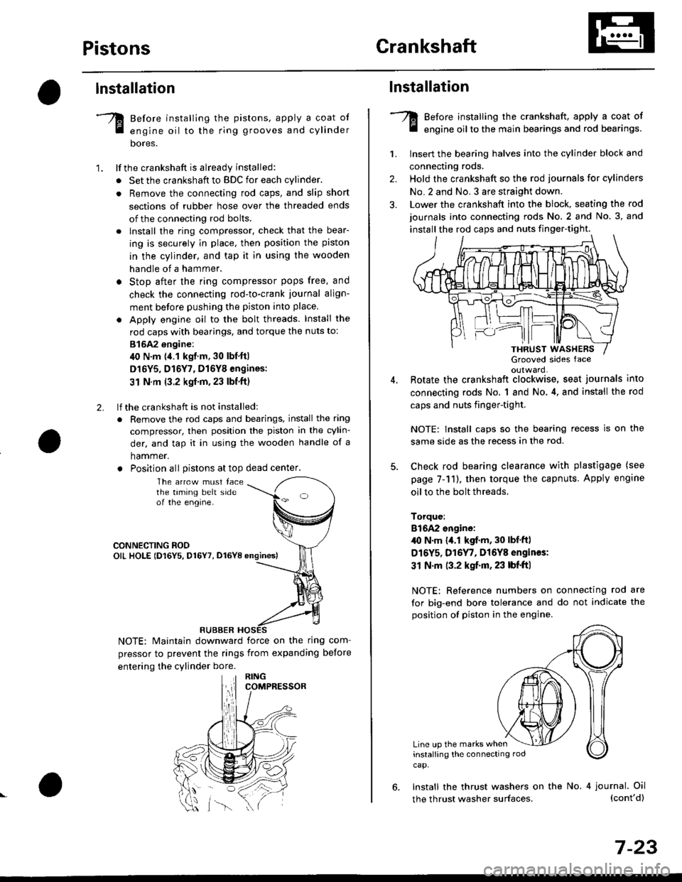
lnstallation
Before installing the pistons, apply a coat of
engine oil to the ring grooves and cylinder
bores.
lf the crankshaft is already installed:
. Set the crankshaft to BDC for each cylinder.
. Remove the connecting rod caps, and slip short
sections of rubber hose over the threaded ends
of the connecting rod bolts.
. lnstall the ring compressor. check that the bear-
ing is securely in place, then position the piston
in the cylinder, and tap it in using the wooden
handle of a hammer.
o Stop after the ring compressor pops free, and
check the connecting rod-to-crank journal align-
ment before pushing the piston into place
. Apply engine oil to the bolt threads. Install the
rod caps with bearings, and torque the nuts to:
815A2 engine:
40 N.m {,1.1 kgf.m, 30 lbf'ft|
D16Y5, D16Y7, D16Y8 engines:
31 N.m (3.2 kgf'm,23 lbf'ft)
lf the crankshaft is not installed:
. Remove the rod caps and bearings, install the ring
compressor, then position the piston in the cylin-
der, and tap it in using the wooden handle of a
hammer.
. Position all Distons at top dead center.
1.
2.
The arrcw must facethe taming belt sideof the engine.
CONNECTING ROOOIL HOLE lD16Y5, D16Y7, D16YB ongines)
NOTE: Maintain downward force on the ring com-
pressor to prevent the rings from expanding before
entering the cylinder bore.
RUBBER
,lll
lnstallation
Before installing the crankshaft, apply a coat of
engine oil to the main bearings and rod bearings.
Insert the bearing halves into the cylinder block and
connecting rods.
Hold the crankshaft so the rod journals for cylinders
No.2 and No. 3 are straight down.
Lower the crankshaft into the block, seating the rod
journals into connecting rods No. 2 and No. 3, and
install the rod caps and nuts finger-tight.
1.
2.
3.
5.
Grooved sides faceoulward.Botate the crankshaft clockwise, seat journals into
connecting rods No, 1 and No.4, and install the rod
caps and nuts finger-tight.
NOTE: Install caps so the bearing recess is on the
same side as the recess in the rod.
Check rod bearing clearance with plastigage (see
page 7-11), then torque the capnuts. Apply engine
oil to the bolt threads.
Torque:
816A2 sngine:/l{, N.m {a.l kgf.m, 30 lbf'ftl
D16Y5, D16Y7, Dl6Y8 engines:
31 N.m (3.2 kgf.m, 23 lbf'ft|
NOTE: Reference numbers on connecting rod are
for big-end bore tolerance and do not indicate the
position of piston in the engine.
Line up the marks wheninstalling the connectrng rod
cap.
6. Install the thrust washers on the No. 4 journal. Oil(cont'd)
7-23
the thrust washer surfaces,
Page 681 of 2189

Description
The automatic transmission is a 3-element torque converter and a dual-shaft electronically controlled unit which provides
4 soeeds forward and 1 reverse.
Torque Convertel, Geats, and Clutches
The torque converter consists of a pump, turbine and stator, assembled in a single unit. They are connected to the engine
crankshaft so they turn together as a unit as the engine turns. Around the outside of the torque converter is a ring gear
which meshes with the starter pinion when the engine is being started. The entire torque converter assembly seryes as a
flywheel while transmiuing power to the transmission mainshaft.
The transmission has two parallel shafts: the mainshaft and the countershaft. The mainshaft is in Iine with the engine
crankshaft. The mainshaft includes the 1st, 2nd and 4th clutches, gears tor 2nd, 4th, reverse and lst (3rd gear is integral
with the mainshaft, while the reverse gear is integral with the 4th gear). The countershaft includes the 3rd clutch, and
gears for 3rd,2nd, 4th, reverse. 1st and park. The gears on the mainshaft are in constant mesh with those on the counter-
shaft. When certain combinations of gears in transmission are engaged by clutches. power is transmitted from the main-
shaft to the countershaft to provide E, ld, E, and E positions.
Electronic Control
The electronic control svstem consists of the Powertrain Control Module {PCM), sensors, a linear solenoid and four
solenojd valves. Shifting and lock-up are electronically controlled for comtonable driving under all conditions. The PCM is
located below the dashboard, under the front lower panel on the passenger's side
Hydraulic Control
The valve bodies include the main vatve body, the secondary valve body, the regulator valve body, the servo body and the
lock-up valve body through the respective separator plates, They are bolted on the torque converter housang
The main valve body contains the manual valve, the 1-2 shift valve. the 2nd orifice control valve, the CPB {Clutch Pressure
Back-up) valve, the modulator valve. the servo control valve, the relief valve, and ATF pump gears The secondary valve
body contains the 2-3 shift valve. the 3-4 shift valve, the 3-4 orifice control valve, the 4th exhaust valve and the CPC (Clutch
pressure Control) valve. The regulator valve body contains the pressure regulator valve, the torque converter check valve,
the cooler relief valve, and the lock-up control valve. The servo body contains the servo valve which is integrated with the
reverse shift fork, and the accumulators. The lock-up valve body contains the lock-up shift valve and the lock-up timing
valve. The linear solenoid and the shift control solenoid valve Ay'B are bolted on the outside of the transmission housing,
and the lock-up control solenoid valve Ay'B is bolted on the outside of the torque converter housing. Fluid from regulator
passes through the manual valve to the various control valves. The clutches receive fluid from their respective teed pipes
or internal hydraulic circuit.
Shift Control Mechanism
Input from various sensors located throughout the car determines which shift control solenoid valve the PCM will activate
Activating a shift control solenoid valve changes modulator pressure, causing a shift valve to move. This pressurizes a line
to one of the clutches, engaging that clutch and its corresponding gear, The shift control solenoid valves A and B are con-
trolled by the PCM.
Lock-up Mechanism
In ,Dt1 position, in 3rd and 4th. and in E position in 3rd, pressurized fluid is drained from the back of the torque converter
through a fluid passage, causing the lock-up piston to be held against the torque converter cover. As this takes place, the
mainshaft rotates at the same as the engine crankshaft. Together with hydraulic control, the PCM optimizes the timing of
the lock-up mechanism. The lock-up valves control the range of lock-up according to lock-up control solenoid valves A and
B, and linear solenoid. When lock-up control solenoid valves A and B activate, the modulator pressure changes The lock-
up control solenoid valves A and B and the linear solenoid are controlled by the PCM.
(cont'd)
14-3
Page 711 of 2189

\
Lock-up System
Lock-up Clutch
1. Ooeration (clutch onl
with the lock-up clutch on, the fluid in the chamber between the torque converter cover and the lock-up piston is drained
off, and the converter fluid exerts pressure through the piston against the torque converter cover, As a result, the conven-
er turbine is locked to the convefter cover. The effect is to bypass the converter, thereby placing the vehicle in direct drive
LOCK.UP PISTONDAMPER SPRING
The power flows by way ot:
Engine
{
Drive plate
i
Torque converter cover
I
Lock-up piston
Damper spring
I
Turbine
Mainshaft
ODeration {clutch off}
With the lock-up clutch off, the fluid flows in the reverse of "clutch on." As a result, the lock-up piston moves away from
the converter cover, and the torque converter lock-up is releassd.
Engine
t
Drive plate
I
Torque convener cover
{
Pump
I
Turbine
Mainshaft
TOROUECOVER
(cont'd)
COI{VERTER
\
TURBNE
MAINSHAFT
14-33