1996 HONDA CIVIC Drive shaft
[x] Cancel search: Drive shaftPage 1138 of 2189
Front Suspension
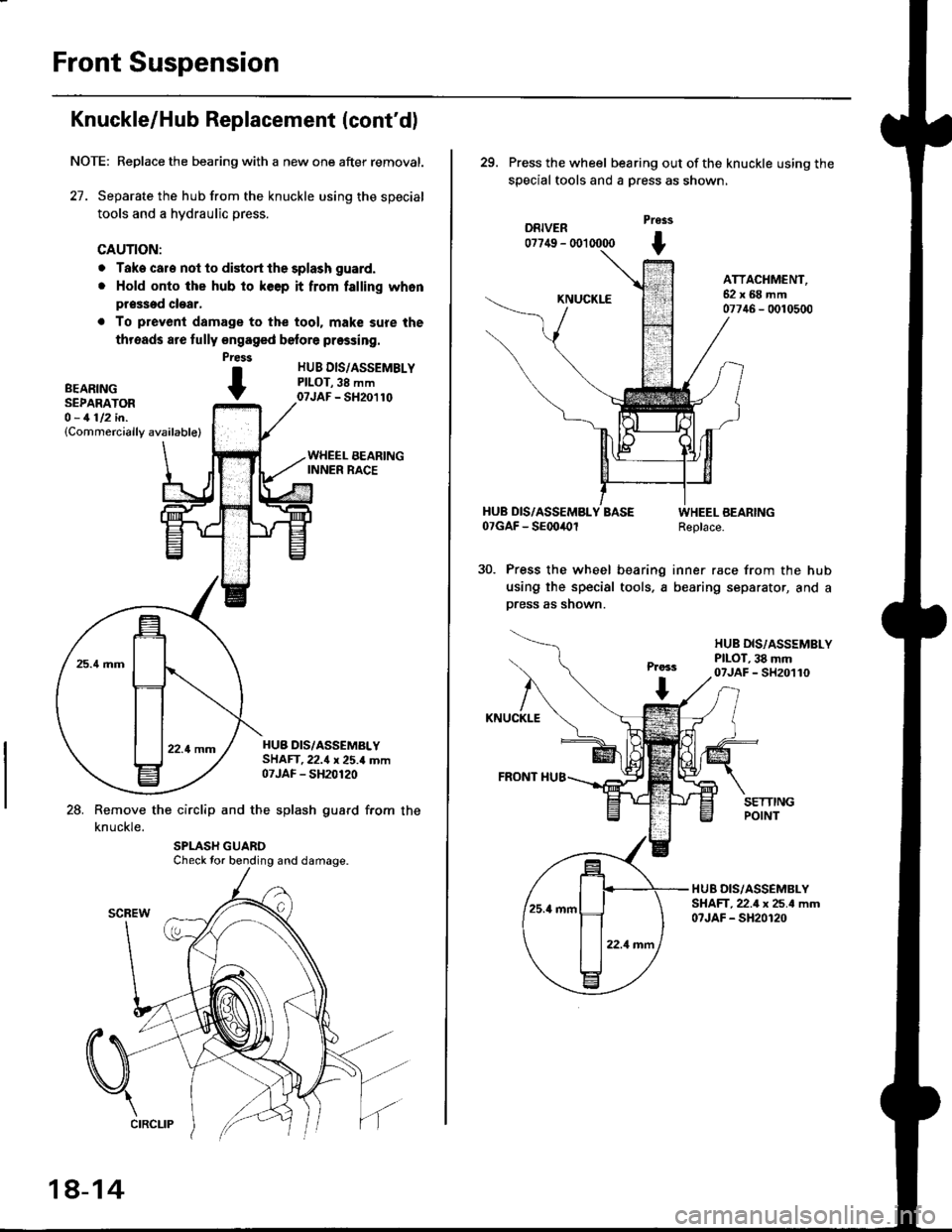
Knuckle/Hub Replacement (cont'dl
NOTE: Replace the bearing with a new one after removal.
27. Separate the hub from the knuckle using the special
tools and a hydraulic press.
CAUTION:
o Take cale not to distort the splash guard.
. Hold onto the hub to keep it from falling whon
pr$sed clear,
. To prevenl damage to the tool. mak€ sure the
threads are fully engaged belore pressing.
HUB DIS/ASSEMBLYPILOT,38 mm07JAF - SH20110
HUB DIS/ASSEMALYSHAFT.22.{ x 25.4 mm07JAF - SH20120
28. Remove the circlip and the splash guard from the
knuckle.
Press
BEARTNG tSEPARATOR -O - 1112 in.(Commercially available)
Check tor bending and damage.
18-14
29. Press the wheel bearing out ofthe knuckle using the
special tools and a Dress as shown,
DRIVER07749 - (X)l 0000
Pross
t
KNUCKLE
ATTACHMENT,62x68mm07746 - 0010500
HUB DIS/ASSEMBLY BASE07GAF - SEoo4Ol
Press the wheel bearing
using the special tools, a
press as shown.
WHEEL BEARINGReplace.
inner race from the hub
bearing separator, and a
HUB DIS,/ASSSMBLYPILOT, 38 mm07JAF - SH20110
KNUCKLE
FRONT I{U8
HUB DIS/ASSEMBLYSHAFT,22.4 x 25.4 mm07JAF - SH20120
Page 1144 of 2189
Front Damper
Installation (cont'd)
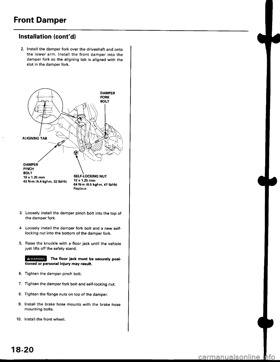
2. Install the damper fork over the driveshaft and onto
the lower arm. Install the front damper into the
damper fork so the aligning tab is aligned with the
slot in the damper fork.
ALIGNING TAB
DAMPERPINCHEOLT10 x 1.25 mm43 N.m 14.4 kgf.m, 32 lbtftl12 x 1.25 mm64 N.m 16.5 kgl.m, 47 lbtftlReplace.
Loosely install the damper pinch bolt into the top ofthe damper fork.
Loosely install the damper fork bolt and a new self-locking nut into the bottom of the damper fork.
Raise the knuckle with a floor jack until the vehiclejust lifts off the safety stand.
@E The ftoor ilck must be sscuroty posi-
lionsd or personal iniury may r€€uh.
Tighten the damper pinch bolt.
Tighten the damper fork bolt and self-locking nut.
Tighten the flange nuts on top of the damper.
Install the brake hose mounts with the brake hose
mounting bolts.
Install the front wheel.
7.
8.
9.
10.
1a-20
Page 1486 of 2189

Connector ldentification and Wire Harness Routing
Engine Wire Harness lD16Y5, D16Y8 enginss): '96 - 98 models
Connector or
Torminal
Numbsr of
CavitissLocationConnects toNot€s
c 101c102c103c104c104c105c106c107c108c 109c110c111c112c113c114c115c116cl17c118c119c120cl21
c122c123cl23c124
c125
c127c12Ac129c130c131c132c 133c134c135
c136
c138c139c140c 141c142c 143c144cl44c145c'146cl47
10
1
22
14l4322l0I
2
2
2
2120
3l
14
14
1222
2
2
22
Left side of engine compartmentMiddle of engineMiddle of engineLeft side of engine companmentLeft side of engine compartmentMiddle of engineMiddle of engineMiddle of engineMiddle of engineMiddle of enginefvliddle of engineMiddle of engineMiddle of engineMiddle of engineMiddle of engineMiddle of engineMiddle of engineLeft side of engine compartmentMiddle of engineMiddle of engineMiddle of engineMiddle of engine
Middle of engineMiddle of engineMiddle of engineMiddle of engineMiddle of engineMiddle of engineMiddle of engineMiddle of engineMiddle of engineRight side of engine companmentBehind right kick panelUnder right side of dashUnder riOht side of dashUnder right side of dashUnder right side of dashUnder right side of dashUnder right side of dash
Under right side of dash
Under right side of dash
Middle of engineMiddle ot enginel iddle of engineMiddle of engineMiddle of ongineMiddle of engineLeft side of engine compartmentMiddle of engineMiddle of engineRight side of engine compartmentRight side of engine compartmentRight side of engine compartment
USACanada
Afi
USA
-' (A/r)
Main wire harness (C303)Crankshaft speed fluctuation (CKF) sensorEngine oil pressure switchAlternatorAlternatorNo. 'l fuel injectorNo. 2 fuel injectorNo.3 fuel injectorNo. 4 fuel injectorIAC valveThrottle position (TP) sensorl\4anifold absolute pressure (MAP) sensorIntake air temperature (lAT) sensorPower steering pressure {PSPI switchEVAP purge control solenoid valveJunction connectorJunction conn€ctorVehicle speed sensor {VSS}Countershaft speed sensorEngine coolant temp€rature (ECT) switch ADistributorEngine coolant temperature (ECT) sendingunrtEngine coolant temperature (ECT) sensorPrimary HO2S (sensor'l)Primary HO2S (sensor 1)Back-up light switchLock-up control solenoid valveSecondary HO2S (sensor 2)Mainshaft speed sensorLinear solgnoid valveShift control solsnoid valveStarter solenoidJunction connectorMain wire harnesE (C446)ECM/PCMPCMECMiPCMECM/PCMMain wire harness (C305)
Main wire harness (C305)
Main wire harness (C305)
Knock sensor (KS)IAC valveVTEC solenoid valveVTEC pressure switchEVAP control canister vent shut valveEGR control solenoid valveSecondary gear shaft speed sensorEGR valveEGR valveDrive pulley speed sensorSolenoid connector {CVT)Driven pulley speed sensor
*, (M/T)M/T*" INT\
*, tAtf)
NT:'96 model*,(A,/T):'97 - 98mooets
moqets
M/T
-1 (l,/T)*, (A,/T)-,(4,/T)*1 {M/T)*, (A,/T)*1 (CW)*, (A,T)
T101r102Left side of engine companmentRight side of engine companmentAlternatorUnder-hood fuse/relay boxG 101Middle of engineEngine ground, via engine wire harness
2
*1: Dl6Y5 engine*2: D16Y8 engine*3: D16Y5 (Ay'T), D16Y8 engines
3-16
Page 1488 of 2189
Gonnector ldentification and Wire Harness Routing
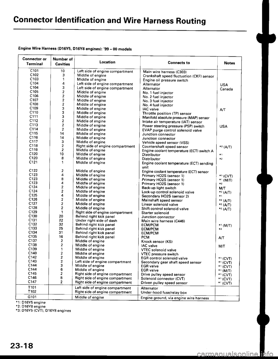
Engine Wire Harness (D16Y5, Dl6Yg engines): ,99 - 00 models
Connectot or
Terminal
Number ot
CavitiesLocationConn€cts toNotes
c'101cl02c103c104c 104c10s
c107c 108c'r09c110c111cl12c113cl14c l15c116cl17c118c119c120cl20c121
c122c123c123cl23cl24c124c125
c127c12Ac129c 130c131cl32c133c 134c135c137c138c 139c 140c142c143c144cl44c145c146c147
103,]
322223332221414322'10
8,l
2484224222120
32
2212223
282
No. 1 luel injector INo.2 fuel injectorNo.3 fuel injector ]No. 4 fuel injector iIAC valve I anThrottle position lTP) sensorManifold absolute pressure {MAP) sensor IIntake air temperature (lAT) sensor IPower steering pressure (PSP)switch USAEVAP purge control solenoid valve ]
Main wire harness 1C303)Crankshaft speed fluctuation (CKF) sensorEngine oil pressure switchAlternatorAlternator
Left side ot engine compartmentlvliddle of engineMiddle of engineLeft side ot engine compartmentLeft side of engine compartmentMiddle of engineMiddle ot engineMiddle of engineMiddle of engineMiddle oI engineMiddle of engineMiddle of engineMiddle of engineMiddle of engineNliddle of engineMiddle of engineMiddle of engineMiddle of engineRight side of engine compartmentMiddle of engineMiddle of engineN4iddle of engineMiddle of engine
Middle of engineMiddle ot engineMiddle ot engineMiddlo of engineMiddle of engineMiddle ot enginelrliddle of engineMiddle of engineMiddle oI engineMiddle ot engineRight side of engine compartmenlBehind right kick panelUnder right side of dashBehind right kick panelBehind right kick panelBehind righr kick panelBehind right kick panelMiddle ot engine[,liddle of engineN4iddle of engineMiddle of engineMiddle oI engineLeft side of engine compartmentMiddle of engineMiddle of engineRight side ol engine compartmentRight side of engine companmentRight side of engine compartment
USACanada
Junction connectorJUnct|On COnnectorVehicle speed sensor lVSS)Countershaft speed sensorEngine coolant temperature {ECT} switch ADistributorDistributorEngine coolant temperature (ECT) sendingunitEngine coolant temperature (ECT) sensorPrimary H02S (sensor 1)Primary HO2S (sensor 1)Primary HO2S lsensor 1)Back-up light switchLock'!p control solenoid valveSecondary HO2S (sensor 2)Mainshaft speed sensorLinear solenoid valveShift control solenoid valveStarter solenoidJunction connectorMain wire harness (C446)ECM/PCMECM/PCMECM/PCMPCtvtKnock sensor (KS)IAC valveVTEC solenoid valveVTEC pressure switchEGR control solenoid valveSecondary gear shaft speed sensorEGR valveEGR valveDrive pulley speed sensorSolenoid connector (CVT)Driven pulley speed sensor
*'� (A/TI
*1 (CVT)*, (M/T)
Mfia (A/Tl
" (A,/T)., (4,/r)-'� {AlrJ
*1 (M/T)
tvliT
*1 (CVT)*, (cvT)*' (cw)*1 (MiT)*1 {CVT)*1 {CVT)*, (cvr)
T101T102Left side of engine companmentRight side ot engine companmentAlternatorUnder'hood fuse/relay boxG 101Middle of englne IEngine ground, via engine wire harness*1: 016Y5*2: D16Y8*3: Dl6Y5
engineengine(CW), D16Y8 engines
23-14
Page 1569 of 2189
JBrush Holder Test
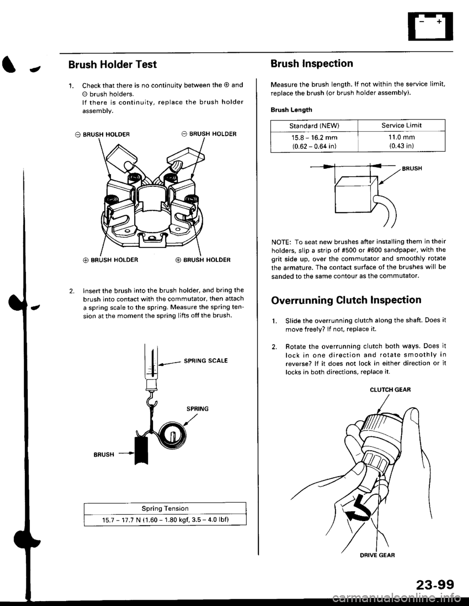
1. Check that there is no continuity between the O and
o brush holders.
lf there is continuity, replace the brush holder
assemoly.
O BRUSH HOLDER
@ BRUSH HOLDER€) BRUSH HOLDER
2. Insert the brush into the brush holder, and b.ing the
brush into contact with the commutator, then attach
a spring scale to the spring. Measure the spring ten-
sion at the moment the spring lifts off the brush.
SPRING SCALE
Spring Tension
15.7 - 17.7 N (1.60 - 1.80 kgf. 3.5 - 4.0 lbf)
ERUSH
Brush Inspection
Measure the brush length. lf not within the service limit,
replace the brush (or brush holder assembly).
Brush Length
NOTE: To seat new brushes after installing them in their
holders, slip a strip ot #500 or #600 sandpaper. with the
grit side up, over the commutator and smoothly rotate
the armature. The contact surface of the brushes will be
sanded to the same contour as the commutator.
Overrunning Clutch lnspection
Slide the overrunning clutch along the shaft. Does it
move freely? lf not, replace it.
Rotate the overrunning clutch both ways. Does it
lock in one direction and rotate smoothly in
reverse? lf it does not lock in either direction or it
locks in both directions, replace it.
2.
L
Standard (NEW)Service Limit
15.8 - 16.2 mm
(0.62 - 0.64 in)
1 1.0 mm
{0.43 in)
CLUTCH GEAR
DRIVE GEAR
Page 1593 of 2189
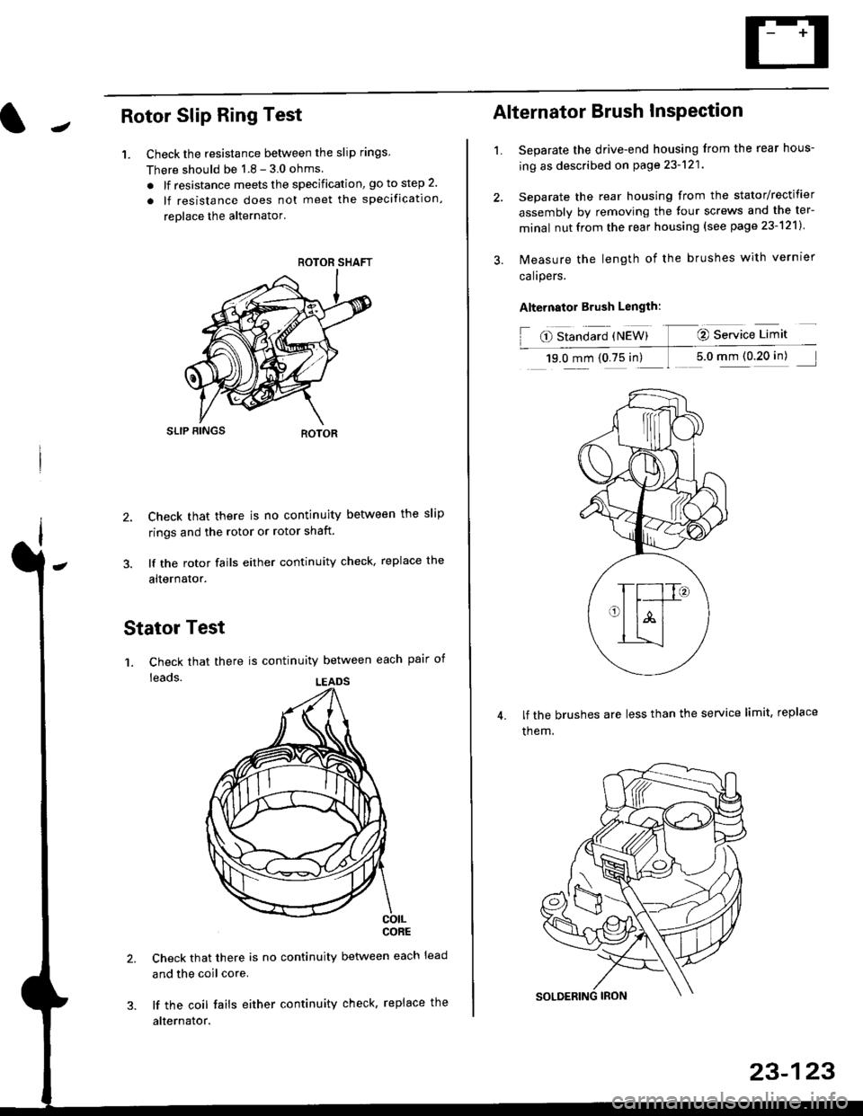
JRotor Slip Ring Test
1. Check the resistance betlveen the slip rings
There should be 1 8 - 3 0 ohms
. lf resistance meets the specification, go to step 2.
. lf resistance does not meet the specification,
reolace the alternator'
SLIP BINGS
2. Check that there is no continuity between the slip
rings and the rotor or rotor shaft.
3. lf the rotor fails either continuity check, replace the
alternator.
Stator Test
'1. Check that there is continuity between each pair of
leads.
CORE
Check that there is no continuity between each lead
and the coil core.
lf the coil fails either continuity check, replace the
alternator.
ROTOR SHAFT
LEADS
1.
Alternator Brush InsPection
Separate the drive-end housing from the rear hous-
ing as described on page 23-121
Separate the rear housing from the stator/rectifier
assembly by removing the four screws and the ter-
minal nutfrom the rear housing {see page 23-121}
lvleasure the length of the brushes with vernrer
calrpers.
Alternator Brush Length:
O Standard {NEW} @ Service Limit
19.0 mm (0.75 in) 1 5.0 mm (0 20 in)
lf the brushes are less than the service limit, replace
them.
23-123
Page 1840 of 2189

Ground-to-Components I ndex
f.,lONOTE: All ground wires are BLK unless otherwise noted.
GroundPageComponents or Circuit Grounded
Battery (BLKYEL)
Steering pump bracket
t+-rg ITransmission housing
l
G101
(-1)
G101
(-2)
14-2
and
14-3
ano
14-1
Powertrain or engine control module (PG1 and pG2 are BLK: LG1 and LG2 are
BRN/BLK), EGR control solenoid valve (CW, EGR valve and lift sensor (Dt6yS enginewith M,/T), Engine coolant temperature switch, pGM-Fl main relay, power steeringpressure switch (USA), Primary HO2S (D16Y5 engine with l\/,/T), Vehicle speed sensor,VTEC pressure switch (D16Y5/D16Y8 engines), CKF sensor (BRN/BLK), Transmission
control module (CYf) (Pc1 is BLK: LG1 is BRN/BLK)
Shielding betvveen the PCM or ECM and these components (all have BRN/BLK wires):
CKF sensor, TDC/CKP/CYP sensor. Primary and secondary heated oxygen sensors.
Knock sensor (CWDl6YB engine), Mainshaft speed sensor (AiT except CVT),
I Countershaft speed sensor (A/T except CVf)
Shielding between the TCM and these components (CVT) (all have BRN/BLK wires):
Drive pulley speed sensor, Driven pulley speed sensor, Secondary gear shaft
speed sensor
Powertrain or engine control module (PG1 and pG2 are BLK; LG1 and LGz are
BRN/BLK), EGR control solenoid valve (D16Y5 engine), EGR valve (Dt685), Engine
coolant temperature switch, Fuel pressure regulator shut-off solenoid valve (D1685),
PGM-FI main relay, Power steering pressure switch (USA), Vehicle speed sensor, VTECpressure switch (All except D16Y7 engine), CKF sensor (A
except 81642) (BRN/BLK)
Shielding between the PCM or ECM and these components (all have BRN/BLK wires):
CKF sensor, TDC/CKP/CYP sensor, Primary and secondary heated oxygen sensors,
Knock sensor (All except D16Y7 engine), i/ainshaft speed sensor (Arf except CW),
Countershaft speed sensor (A,/T except CVf), Drive pulley speed sensor (CW), Drivenpulley speed sensor (CVT), Secondary gear shaft speed sensor (CVf)
I Badiator fan motor, Right front parking/turn signat tight, Right headtight
G20214-4I Cruise control actuator, Left front parking/turn signal lights, Left headlight, Rear window
I washer motor, Windshield washer motor, Washer fluid level switch (,99-'00 Canada)
G401| +-o
and
14-7
Accessory power socket, Brake fluid level switch, Clutch interlock switch (M/T), Clutchswitch (lillT with cruise/D16Y5 engine with MfD, Combination wiper switch (Z wires),
Cruise control main switch, Cruise control unit, Dash lights brightness controller, Data
link connector, Daytime running lights control unit (Canada), Gauge assembly, Horn('96-'97 models), Integrated control unit, Interlock control unit (ArI), Keyless door lock
control unit ('99-'00 models with keyless), Moonroof close and open relays, Moonroof
switch, Park pin switch (A/r), Power window relay, Rear window defogger relay, Rear
window defogger switch ('96-'98 models), Steering lock, Stereo radio tuner (,96-,98
USA: LX, EX, and HX), Turn signal/hazard relay, Windshield wiper motor.....plus
everything grounded through G402
6-6
Page 1858 of 2189
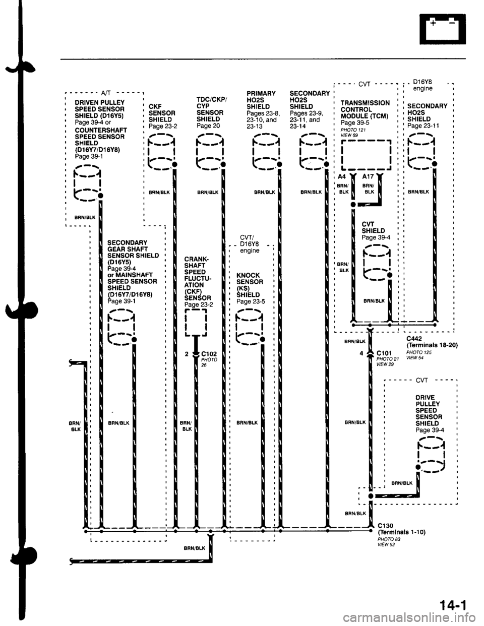
----" A/T -----t
DRIVEN PULLEY , ^.,.
;iftTBilis'".f l5Ftr,.""_
co'rinienixnn '. Pase 23'2
SPEED SENSOR ; .'-\.SHIELD 'F--.1
TDC/CKP/CYPSENSORSHIELDPage 20
ll
r_:.-i
23-13
t1
23- l4
tl
PRIMARY SECONDARYHO2S HO2SSHIELD SHIELDPages 23-8, Pages 23-9,23-10. and 23-11. and
--- CW ----.
TRANSMISSION ;CONTROLMODULE(TCM) ,Page 39-5 :PHO|O 121vlEw 69r____1 ,
tt:
tt:L----J,
. D16Y8engine
SECONDARY .
HO2S :SHIELD ;Page 23-11
l. - -..1 ;
tt:(D16Y/i D15Y8)Page 39-1
l.--.1
1l
r:--iBFN/BLKARN/BLK
A4
6FN/BLK' EFN/BI
i i srco"oo"t :' I GEAR SHAFT
I I Or MAtN!'tAt I. II SPEED SENSOR '
CW. - D16Y8 -, engine: N SENSoR SHTELD ,
i !i?il3li*u,, i
CWSHIELD :Page39-4,
CRANK-SHAFTSPEEDFLUCTU-ATION(cKF)SENSORPage 23-2
tl
ll
;I;..
26
i xNocx' SENSOR, (KS)' SHIELD
, Fage zJ-5
: F--.1
:ll
iilr-:i
----:.--------:
c442(Terminals 18-20)
c10.1 PHofo 125\HOTO 21 VIEW 54vtEw 29
'----- cw ----'
DRIVE
BFN/BLK
PULLEY :SPEEDSENSORSHIELDPage 39-4 :
1.---{ :I t;
cl30Oermlnal8'l-10)
vtEw 52
14-'�,