Page 112 of 2189

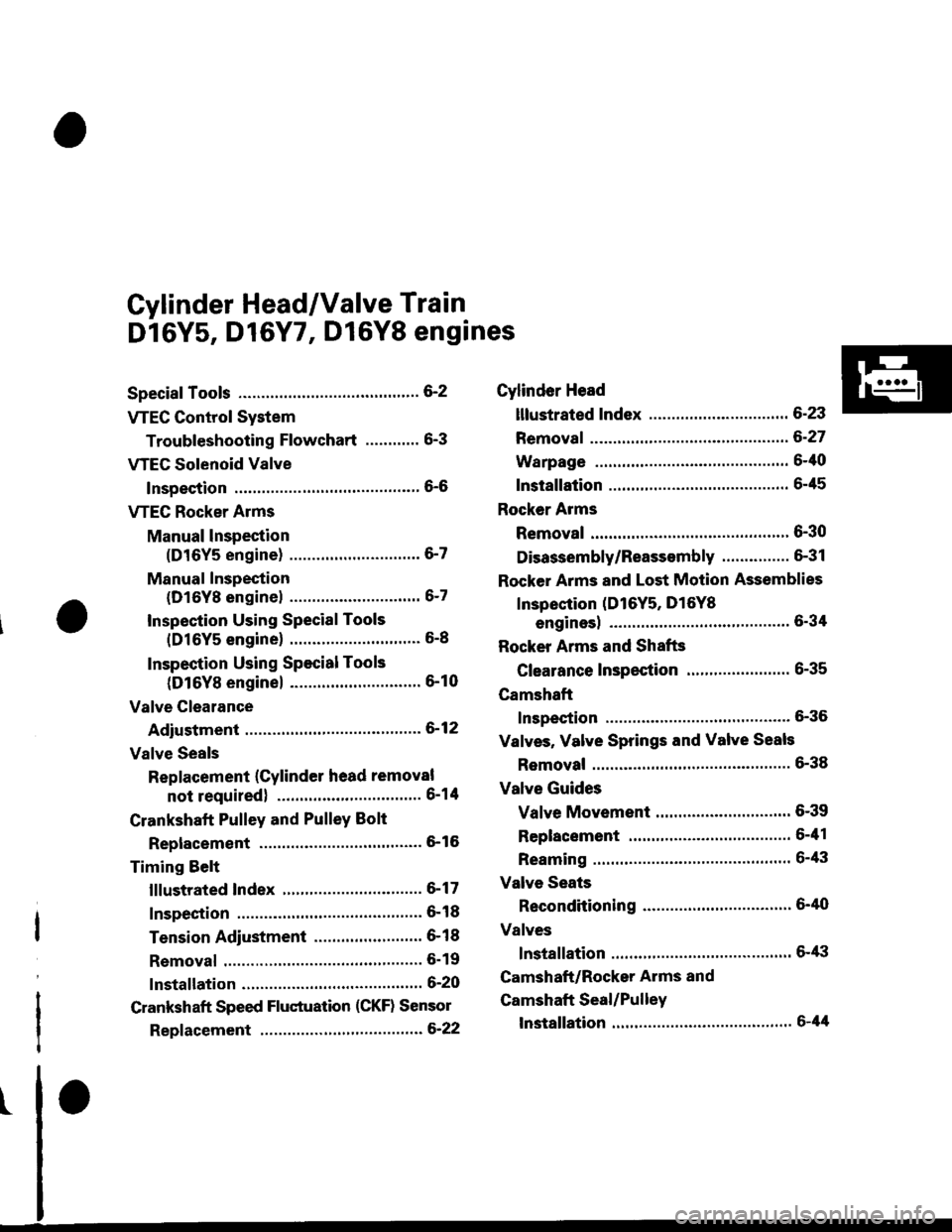
Cylinder Head/Valve Train
Dl6Y5, D16Y7, Dl6Y8 engines
Special Tools ............. G2
VTEC Control System
Troubleshooting Flowchart .........." 6-3
VTEG Solenoid Valve
Inspection ............" 6-6
VTEC Rocker Arms
Manual lnspection
(D16Y5 engine) ............................. 6-7
Manual Inspection
(D16Yg enginel ................'............ 6-7
Inspection Using Special Tools
{D16Y5 engine} .....................""'... 6-8
Inspection Using Special Tools
(D16Y8 engine) .........................'.'. 6-10
Valve Clearance
Adiustment ..."".....6-12
Valve Seals
Replacement (Cylinder head removal
not requiredl ................................ 6-1tl
Crankshaft Pulley and PulleY Bolt
Replacement ."...... &16
Timing Selt
lllustrated Index ............................... 6-17
Inspection .............. 6-18
Tension Adjustment ........................ 6- 1 I
Removal ......,,......... 6-19
lnstallation ............. 6-20
Crankshaft Speed Fluctuation (CKF) Sensor
Repf acement .........6'22
Cylinder Head
lllustrated Index ............................... 6-23
Removal ................. 6-27
Warpage ................ 6-40
lnstallation ............. 6-45
Rocker Arms
Removal ................. 6-30
Disassembly/Reassambly ............... 6-31
Rocker Arms and Lost Motion Assemblies
Inspection (D16Y5, D16Yg
enginesl "..........' 5-34
Rocker Arms and Shafts
Glearance Inspection ....................... 6-35
Camshaft
Inspection .............. 6-36
Valves, Valve Springs and Valve Seals
Removal ........""..... 6-38
Valve Guides
Valve Movement .............................. 6-39
Replacement .........6-41
Reaming .......'......'.' 6-43
Valve Seats
Reconditioning .'....6'40
Valves
lnstallation ............. 6-tt3
Camshaft/Rocker Arms and
Camshaft Seal/Pulley
lnstallation ............. 6-44
Page 121 of 2189
VTEC Rocker Arms
Inspection Using Special Tools (D16Y8 enginel
CAUTION:
o Before using the Valve Inspection Tool. mak6 surethat the air pressure gauge on the air comprsssor
indicates ovor 400 kPa {4 kgf/cm,, 57 psil.
. Inspect th6 valve clearanco before rockar arm inspec-
tion.
. Cov€r th€ timing belt with a shop towel to protect
the bolt.
. Check tho intake prima.y rockff arm of each cylindel
at TDC.
1.Remove the cylinder head cover.
NOTE: Refer to page 6-46 when installing the cylinder
neao cover,
Plug the relief hole with the specialtool.
OTLAJ - PR3O2OB
I,^ A IAo- tu
3. Remove the sealing bolt from the inspection hole
ancl connect an air pressure regulator with a 0 - 100psi gauge.
l0 x 1.0 mmSEALING EOLT20 N.m (2.0 kgf.m, 14 lbf.ft)
(AIR PRESSUREREGULATOR
{Commerciallyavailable). Pullthe dialandturn to adjust,
Page 138 of 2189

Removal
Engine removal is not required for this procedure
!!!s@ Make sure iacks and salety stands are
f ta"eata"ea propetty and hoist brackets are attached to the
correct positions on the engine.
CAUTION:
. Use tender covels to avoid damaging painted sul-
faces.
o To avoid damage, unplug the wiling connectors
carefully while holding the connector portion to
avoid damage.
. To avoid damaging the cylinder head, wait until the
engine coolant temperature drops below 100"F
{38"C} before loossning the tetaining bolts.
NOTE:
o Mark all wiring and hoses to avoid misconnectlon
Also, be sure that they do not contact other wiring or
hoses, or interfere with other parts.
. Inspect the timing belt before removing the cylinder
h ead.
. Turnthe crankshaft pu lley so that the No. lpistonisat
top dead center (see Page 6-21)
'1. Disconnect the negative terminal from the battery'
Drain the engine coolant (see page'10-7).
a Remove the radiator cap to speed draining.
Remove the intake air duct and air cleaner housing
(see page 5 3).
Remove the mounting bolt and lock bolt. then
remove the power steering (P/S) pump belt and
pump (see page 5'5).
Loosen the idler pulley center nut and adjusting
bolt' then remove the air conditioning (A'lc) com-
pressor belt (see Page 5-6).
Loosen the mounting nut and lock bolt. then
remove the alternator belt (see page 6-19).
Remove the P/S pump bracket (see page 5-12).
3.
4.
2.
6.
1.
8. Remove the throttle cable by loosening the locknut,
then slip the cable end out of the throttle linkage
NOTE:
. Take care not to bend the cable when removing it
Always replace any kinked cable with a new one
. Adjust the throttle cable when installing (see sec-
tion 1 1).
D16Y7 engine:
Dl6Y5, Dl6Y8 engines:
THFOTTLECABLE
(cont'd)
6-27
LOCKNUT
CABLE
Page 143 of 2189
Rocker Arms
Disassembly/Reassembly (cont'dl
NOTE:
. ldentify pans as they are removed to ensure reinstallation in original locations.. Inspect rocker shafts and rocker arms (see page 6-34).. Rocker arms must be installed in the same position if reused.t when removing or installing the rockerarm assembly, do not remove the camshaft holder bolts. The boltswill keeptheholders, springs and rocker arms on the shaft.
I erior to reassembring, crean a
the parts in sorvent, dry them and appry rubricant to any contact points.
D16Y5 engine:
ROCKER ARMS
TIMING PLATERUBBER BANO
(\
-]-
-P'g,rpt+.t't ll
\--,?|, -\2i lNo.5 CAMSHAFT _ lHOLDER l
No. 4 CAMSHAFTHOLDERNo. 3 CAMSHAFIHOLDERNo.2HOLDER
ra
I
EXHAUST ROCKERARM B{,1 plac€s)
EXHAUST ROCKEE SHAFT
Letter "A" is slamped
II{TAKE ROCKER SHAFT
!-r I
?h'ffi*ffi'
/^ ---IOCKER SHAFT
Letter "8" is stamped
6-32
Page 145 of 2189
Rocker Arms and Lost Motion Assemblies
Inspection (D16Y5, Dt6Y8 enginesl
NOTEr When reassembling the primary rocker arm,carefully apply air pressure to the oil passage of therocker arm.
1. Inspect the rocker arm piston. push it manually.- lf it does not move smoothly, replace the rockerarm assembty.
Dl6Y5 engine:
ROCKER ARM
TIMING PISTON
TIMING SPRING
SYNCHRONTZINGPISTON
SECONDARYROCKER ARM
MID ROCKER ARM
PRIMARY ROCKER
SYNCHRONIZINGPISTON A
NOTE:
. Apply oil to the pistons when reassembling.o Bundle the rocker arms with a rubber band to preventthem from separating.
6-34
(\
DI6YS engine:
NOTE: Set the timing plate and return spring as shownoerow.
RETURN
CAMSHAFT HOLDER
Dl6Yg engine:
2. Remove the lost motion assembly from the holderand inspect it. Test it by pushing the plunger withyour finger.- lf the lost motion assembly plunger does notmove smoothly, replace it.
LOST MOTION ASSEMBLY
\a
Pu3h
I
Page 148 of 2189

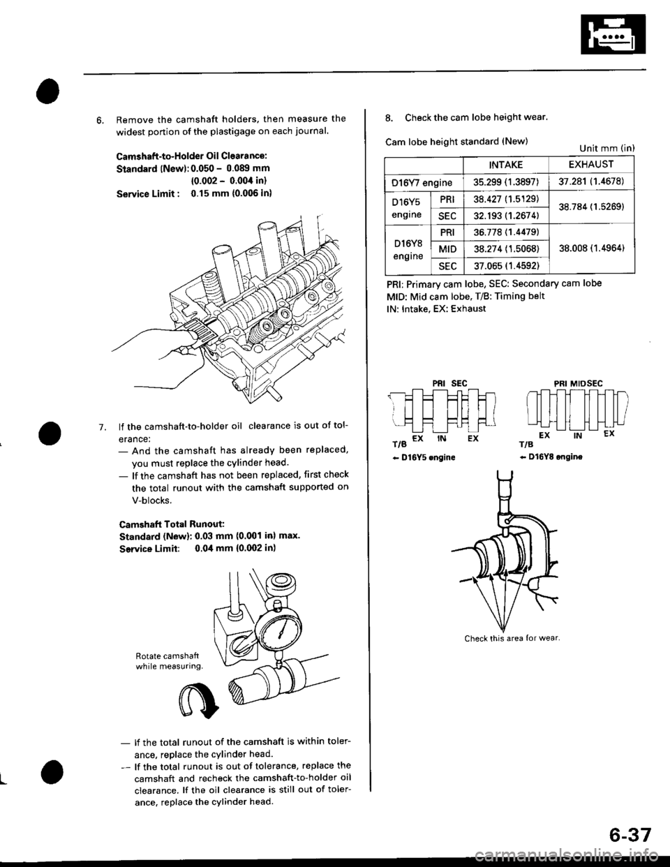
6, Remove the camshaft holders. then measure the
widest ponion of the plastigage on each journal.
Camshaft-to-Holder Oil Clearance:
Standard lNew):0.050 - 0.08!t mm
{0.002 - 0.004 in}
Service Limit : 0.15 mm {0.006 in)
lf the camshaft-to-holder oil clearance is out ot tol-
erance:- And the camshaft has already been replaced,
you must replace the cylinder head.
- lf the camshaft has not been replaced, first check
the total runout with the camshaft supported on
V-blocks.
Camshaft Total Runout:
Standard (New): 0.03 mm (0.001 inl max.
Service Limit: 0.04 mm {0.(X)2 in)
-7.
Rotate camshattwhile measuring.
L
- lf the total runout of the camshaft is within toler-
ance, replace the cylinder head.
- lf the total runout is out of tolerance, replace the
camshaft and recheck the camshaft-to-holder oil
clearance. lf the oil clearance is still out of toler-
ance. replace the cylinder head.
INTAKEEXHAUST
O16Y/ engine35.299 (1.3897)37.281 (1.4678)
D16Y5
engrne
PRI38.427 11.5129138.784 (1.5269)
SEC32.193 (1.2674)
D l6Y8
engrne
PRI36.77811.44791
38.008 (1.4964)MID38.274 (1.5068)
sEu37.065 (1.4592)
8. Check the cam lobe height wear.
Cam lobe height standard (New)
t/g a* rN Ex
- D16Y5 engine
PRI; Primary cam lobe, SEC: Secondary cam lobe
MtD: Mid cam lobe. T/B: Timing belt
lN: Intake, EX: Exhaust
PRIsEcMIDSEC
rts
- Dl6YE ongine
Unit mm (in)
Check this area {or wear.
6-37
Page 215 of 2189

Connecting RodsPiston Pins
Selection
Each rod falls into one of four tolerance ranges {from O to+ 0.024 mm (0 to + 0.0009 in), in 0.006 mm (0.0002 in)increments) depending on the size of its big end bore. lt,sthen stamped with a number {1, 2,3, or 4) indicating therange.
You may find any combination ot l, 2, 3, or 4 in any
engrne.
Normal Eore Size: 48.0 mm (1.89 in)
NOTE:
o Reference numbers are for big end bore size and doNOT indicate the position of the rod in the engine.. Inspect connecting rod for cracks and heat damage.
CONNECTING ROD AOREREFERENCE NUMBERHalf of number is stamped onbearing cap, the other half onconnectrng rod.
7-18
Installation
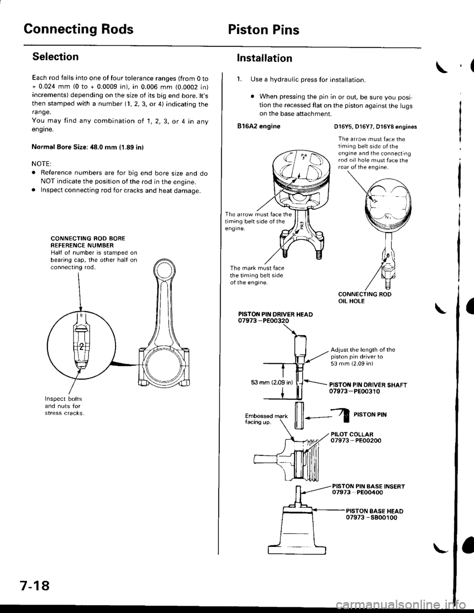
1. Use a hydraulic press for installation.
. When pressing the pin in or out, be sure you posi
tion the recessed flat on the piston against the lugson the base attachment.
816A2 engine
The arrow must face thetiming belt side of theeng Ine.
The mark must facethe timing belt sideof the engine.
D16Y5, D16Y7, O16Y8 engines
The arrow must face thetiming belt side o{ theengine and the connectingrod oil hole must face therear of the engine.
Adjust the length of thepiston pin driver to53 mm (2.09 4n)
PISTON PIN DRIVER SHAFT07973-PEOo3r0
PISTON PIN DRIVER HEAD
il--Z
P,"roNPrN
PILOT COLLAR07973-PE00200
PISTON PIN BASE INSERT07973 PEO0400
PISTON EASE HEAO07973 -5800100
,(
a
Page 239 of 2189

4.
Removal/lnspection/lnstallation
2.
3.
1.
5.
6.
1.
8.
Drain the engine oil.
Turn the crankshaft and align the white groove on
the crankshaft pulley with the pointer on the lower
cover.
Remove the cylinder head cover and upper cover'
Remove the power steering pump belt, air condi-
tioner beit and the alternator belt
Remove the crankshaft pulley and remove the lower
cover.
Remove the timing belt.
Remove the drive pulley.
Remove the oil pan and oil screen.
O.RINGReplaceOOWEL PIN
OIL SCREEN
9. Remove the oil PumP.
!'a
10.Remove the screws from the pump housing, then
separate the housing and cover'
Check the inner-to-outer rotor radial clearance on
the pump rotor. lf the inner-to outer rotor clearance
exceeds the service limit, replace the inner and
outer rotors.
lnner Rotor-to-Outer Rotor Radial Clearance
Standard {New}: 815A2 engine 0.04 - 0.16 mm
(0 002 - 0'006 in)
D16Y5, D16Y7, D16Y8 engines
0.02 - 0.14 mm 10.001 - 0.006 in)
Service Limit: 0.20 mm (0 008 inl
OUTER ROTOR
INNER ROTOR
Check the housing-to-rotor axial clearance on the
pump rotor. lf the housing-to rotor axial clearance
exceeds the service limit, replace the set of inner
and outer rotors and/or the pump housing
Housing-to-Rotor Axial Clearance
Standard (N€w): 816A2 engine 0.02 - 0.07 mm
(0.001 - 0.003 inl
D16Y5, D16Y7, D16Y8 engines
0.03 - 0.08 mm (0.001 - 0.003 inl
S€rvice Limit: 0.15 mm 10.006 in)
11.
't2.
(cont'd)
8-13