1996 HONDA CIVIC Dash harness
[x] Cancel search: Dash harnessPage 546 of 2189

\
'99 - 00 models excepi Dl6Y5 engine with M/T:
The scan tool indicates Diagnostic Trouble Code (DTC) P0452: A low voltage problem in the Fuel Tank Pressure
sensor.
The fuel tank pressure sensor converts fuel tank absolute pressure into electrical signals and inputs the ECM/PCM
OUTPUTVOLTAGE(vlt.5
0.5-7 kP.(-g) mmHg,-2 in.Hgl
+7 kP.
150 mmHg,2 in.Hgl
PRESSURE
I
Wire side of lemale terminals
FUEL TANKPRESSURE SENSORSUB.HARNESS6P CONNECTOR (C574 (C568)rl
vcc2(YEL/BLUIsG2{GRN/BLK}
Wire side o{ temale terminals
The MIL has been .eported on.
DTC P0452 is stored
Check the vacuum lines:
Check the vacuum lines of the
fuel tank pressure sensor lor mis-
routing, leakage, breakage and
cloggrng.
Are the vacuum hnes OK?
Problem veritication:1. Do the ECM/PCM Reset Proce-
du re,2. Bemove the fuel fill caP.
3. Turn the ignition switch ON {ll)
4. Monitorthe FTP Sensor voltage
with the Honda PGM Tester' or
measure voltage between body
groLrnd and ECM/PCM connec_
tor terminalA29.
lntermitlent tailure, 3Ystem b OK
at this time. Check for Poor con'
nections or loose wire3 at C131
{located under right side of dash},
C401 {located above under'dash
tuse/relay box), C574 (C568)*
llocdted under access Panel),C792 (tuel rank Prcssure sensorl
and ECM/PCM.
ls there approx.2 5 V?
Check for an open in wire {VCC2
line):1. Turn the ignition switch OFF.
2. Reinstall the ltrel fill caP
3, Remove the access Panel from
the floor.4. Disconnect the fuel tank Pres'sure sensor sub-harness 6P
5. Turn the ignition switch ON (ll).
6. At the access Panel side, mea_
sure voltage between the fuel
tank Pressure sensor sub-nar-
ness 6P connector No 5termi
nal and No. 6 termlnal.
Repair open in tho wire between
th6 fu€l tank Prossuro sen3oa and
the ECM/PCM lc28).ls there approx 5 V?
ECM/PCM CONNECTOR A (32P)
PTANK {LT BLUI
I
ll
(To page '11-278)
(cont'd)
Page 550 of 2189

\
'99 - 0O modols except Dl5Y5 engine with M/T:
rFo45'::n":"tooIindicatesDiagnosticTroub|ecode(DTc)P0453:Ahighvo|tageprob|emintheFUelTankPressure
Wire side of temale terminals
FUEL TANKPRESSUNE SENSOR
SUB.HARNESS6P CONNECTOR {C574 (C568)}}
vcc2{YEL/BLUI
sG2IGRN/BLK)
Wire side of female terminals
PTANK{LT GRNI
(cont'd)
11-281
ECM/PCM CONNECTOR A {32P)
PTANK {LT GRN)
The MIL has been reported on.
DTC P0453 is stored.
Check the vacuum lines:
Check the vacuum lines ot the
fuel tank pressure sensor for mis-
routing, leakage, breakage and
clogging.
Are the vacuum lines OK?
Problem verilication:1. Do the ECM/PCM Reset Proce-
du re,2. Remove the fuel fill caP
3. Turn the ignition switch ON (ll).
4. Monitor the FTP Sensor volt'
age with the Honda PGM
Tester, or measure voltage
between body ground and
ECM/PCM connector terminalA.29.
lntermittent failuro. svstem b OK
at this time. Check for Poor con_
noctions or loo3€ wire3 at C131
{located under tight side of dash),
C4Ol {located above underdash
fuse/relay boxl, C57{ (C5681'
llocaled unde. access Panell,C792 {fuel tank Pressure sensorl
aod ECM/PCM.
ls there approx.2.5 V?
Ch€ck for an open in the wira
{SG2line):1. Turn the ignition switch OFF.
2. Reinstall the fuel fill caP
3. Remove the access Panellrom the floor.
4. Disconnect the fuel tank Pres-sure sensor sub-harness 6P
5. Turn the ignition switch ON (ll)
6, At the access Panelside, mea-
sure voltage between the fuel
tank pressure sensor sub_har-
ness 6P connector termlnals
No.5 and No.6.
Repair open in the wire between
the fueliank Pres3ure 3ensor and
ECM/PCM {Cl8).ls there approx.5 V?
Check lor an oPen in the wire
{PTANK linel:At the access Panel side, mea
sure voltage between the fuel
tank pressure sensor suo_harness
6P connector No. 2 terminal and
No. 6 terminal.
ls there approx. 5 V?
(To page 11.282)
Page 1093 of 2189
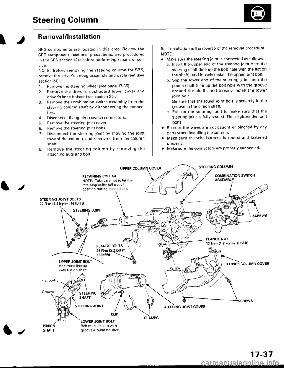
Steering Column
I
Removal/lnstallation
SRS components are located in this area. Review the
SRS component locations, precautions, and proceclures
in the SRS sectron (24) before pertorming repairs or ser-
vice.
NOTE: Before removing the steering column for SRS,
remove the driver's airbag assembly and cable reel lsee
section 24).
1. Remove the steering wheel (see page 17 35).
2. Remove the driver's dashboard lower cover and
driver's knee bolster (see section 20).
3. Remove the combination switch assembly from the
steering column sha{t by disconnecting the connec-
tors.
4. Disconnect the ignition switch connectors.
5. Remove the steering joint cover.
6. Bemove the steering joint bolls.
7. Disconnect the steering ioint by moving the joint
toward the column, and remove it from the column
shaft.
8. Remove the steering column by removing the
attaching nuts and bolt.
UPPER
RETAINING COLLABNOTE: Take care not to let the
retaining collar fall out ofposition during installation.
STEERING JOINT BOLTS22 N.m {2.2 kgf.m, 16lbtft}
9. Installation is the reverse of the removal procedure
NOTE:
. Make sure the steering joint is connected as follows:
a. Insert the upper end of the steering ioint onto the
steering shaft (line up the bolt hole with the flat on
the shait), and loosely install the upper joint bolt.
b. Slip the lower end of the steering joint onto the
pinion shaft (line up the bolt hole with the groove
around the shaft), and loosely install the lower
joint bolt.
Be sure that the lowei joint bolt is securely in the
groove in the pinion shaft.
c. Pull on the steering joint to make sure that the
steering joint js fully seated. Then tighten the ioint
bolts.
. 8e sure the wires are not caught or pinched by any
parts when installing the column
. Make sure the wire harness is routed and fastened
properly.
. Make sure the connectors are properly connected.
STEERING COLUMN
COMBINATION SWITCHASSEMBLY
FLANGE NUT13 N.m {1.3 kgl.m.9 lbf ft)
COLUMN COVER
FLANGE BOLTS22Nm12.2kgl'm,16 tbt.tr)
UPPER JOINT BOLTBolt musl line upon shaft.
Groove.
LOWER JOINT BOLT8oh must line up wrthgroove around on shaft.
CLIP
J
JOINT COVER
17-37
Page 1284 of 2189
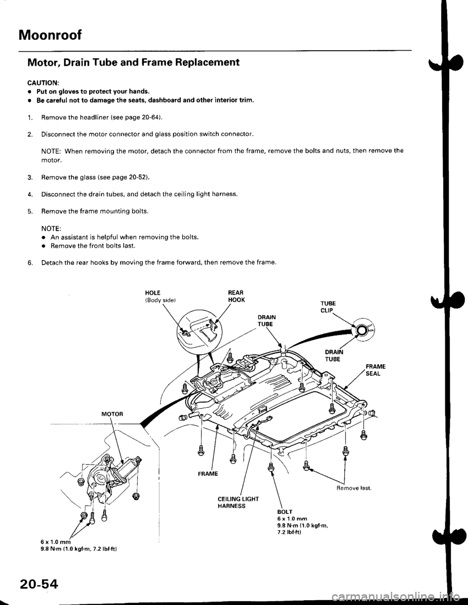
Moonroof
Motor, Drain Tube and Frame Replacement
CAUTION:
. Put on gloves to protecl your hands.
. Be careful not to damage the seats, dashboard and other interior trim.
'1. Remove the headliner {see page 20-64).
2. Disconnect the motor connector and glass position switch connector.
NOTE: When removing the motor, detach the connector from the frame, remove the bolts and nuts, then remove the
motor.
3. Remove the glass {see page 20-52).
4. Disconnect the drain tubes, and detach the ceiling light harness.
5. Remove the frame mounting bolts.
NOTE;
. An assistant is helpful when removing the bolts.
. Remove the front bolts last.
6. Detach the rear hooks by moving the frame forward, then remove the frame.
BOLT6x1.0mm9.8 N.m {1.0 kgt m,7.2 tht.hl
6x1.0mm9.8 N m (1.0 kgl.m, 7.2 lbtft)
20-54
\
Page 1300 of 2189
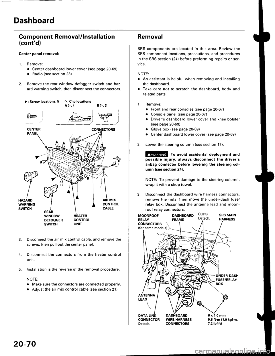
Dashboard
Gomponent Removal/lnstallation
(cont'd)
Center panel removal:
1. Remove:
. Center dashboard lower cover (see page 20-69)
. Radio {see section 23)
2. Remove the rear window defogger switch and haz-
ard warning switch, then disconnect the connectors.
>: Screw locations, 5 >: Clip locationsA>,4 B>,3
fii*-)
CENTERPANEI.
rt-xR.
W
IHAZARDWARNINGswlTcH
r44 "
F.IZvl
IIREARwtNoowOEFOGGERswtrcH
MtxCONTNOLCABLE
3. Disconnect the air mix control cable, and remove the
screws, then pull out the center panel.
4. Disconnect the connectors from the heater control
u nit.
5. Installation is the reverse of the removal procedure.
NOTE:
. Make sure the connectors are connected properly.
. Adjust the air mix control cable (see section 21).
20-70
Removal
SRS components are located in this area. Review the
SRS component locations, precautions, and procedures
in the SRS section (24) before preforming repairs or ser-
vice.
NOTE:
. An assistant is helpful when removing and installing
the dashboard.
. Take care not to scratch the dashboard, body and
related parts.
1. Remove:
o Front and rear consoles (see page 20-67)
. Console panel (see page 2O 67),
. Driver's dashboard lower cover and knee bolster(see page 20-68)
. Glove box (see page 20-69)
. Center dashboard lower cover (see page 20-69i
2. Lower the steering column (see section 17).
@ To avoid accidental deplovment and
possible injury, always disconnect the driver's
airbag connector belore lowering the steering col-
umn lsee section 241.
NOTE: To prevent damage to the steering column,
wrap it with a shop towel.
3. Disconnect the dashboard wire harness connectors,
remove the nuts, then move the under-dash fuse/
relay box. Disconnect the antenna lead and moon-
roof relay connectors.
DASHBOARD cltPs
CONNECTORS(for some models)
MOONROOFRELAY
ANTENNALEAO
FRAME
SRS MAINHARNESS
9.8 N.m (1.0 kgf m,7.2lbt.ltl
DATACONNECTOR WIRE HARNESSDetach. CONNECTORS
Page 1302 of 2189
![HONDA CIVIC 1996 6.G Workshop Manual Dashboard
Removal (contd)
7. lf necessary, remove the dashboard frame from the dashboard.
>: Screw localionsa>,21 B>,4a: Nut locations, 3
>: Clip locations
l^1./\
I Shl: OlbtvY/l\-]1
ra 6 x 1.0 m HONDA CIVIC 1996 6.G Workshop Manual Dashboard
Removal (contd)
7. lf necessary, remove the dashboard frame from the dashboard.
>: Screw localionsa>,21 B>,4a: Nut locations, 3
>: Clip locations
l^1./\
I Shl: OlbtvY/l\-]1
ra 6 x 1.0 m](/manual-img/13/6068/w960_6068-1301.png)
Dashboard
Removal (cont'd)
7. lf necessary, remove the dashboard frame from the dashboard.
>: Screw localionsa>,21 B>,4a: Nut locations, 3
>: Clip locations
l^1./'\
I Shl:' Olb'tvY/l\-]1
ra 6 x '1.0 mm
Yi.!i[11"-"'".
DASHBOARD BRACKETSIDE COVER
Installation is the reverse of the removal orocedure.
NOTE:
. Before tightening the bolts, make sure the dashboard wire harnesses are not pinched.a Make sure the connectors, antenna lead and air mix control cable are connected properly.
FRONT PASSENGER'S
OASHBOARD
20-72
Page 1411 of 2189
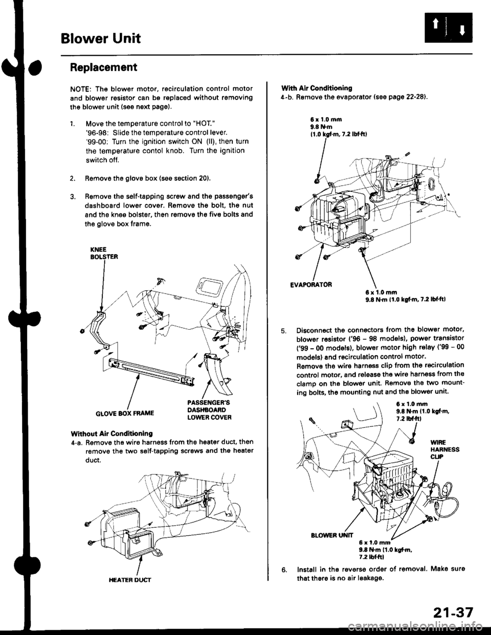
Blower Unit
Replacement
NOTE: The blower motor, recirculation control motor
and blower resistor can bs replacsd without rsmoving
th€ blower unit (see neld Page).
1. Move the temperature control to "HOT."
'96-98: Slide the temperature control lever.'99-00: Turn the ignition switch ON (ll), then turn
the temperature contol knob. Turn the ignition
switch off,
Remove the glovs box (ses ssction 20),
R€move ths s6lf-tapping screw and ths passsng6r's
dashboard low€r cover. Removo the bolt, the nut
and the kn€e bolst€r, then remove the fiv€ bolts and
the glove box trame,
Without Air Condhioning
4-a. Remove the wiro harness from the h68t€r duct, then
remove the two self-tapping scrsws and the heatsr
duct.
KNEE
GLOVE BOX FRAME
HEATER DUCT
21-37
Wrth Air Conditioning
4-b. Removo th6 ev8porator (sss pago 22-28).
6x1.0m|n9.8 N'm
6x1.0mm9.8 N'm lt'o tgf'm, t.2 lb{'ttl
Disconnoct the connectors trom th€ blower motor,
blowor r6sistor {'96 - 98 models), power transiator
('99 - 0O modsls), blowor motor high telay ('99 - 00
models) and recirculation control motor.
R€mov€ ths wiro harnoss clip from tho recirculation
control motor, and release the wir6 harnsss from ths
clamo on the blowor unit. Remove the two mount-
ing bolts, tho mounting nut and ths blowor unit'
9.8 .m 11.0 tgfm,1.2 tblfrl
lnstall in ths reverso order of removal. Mako surs
that thsre is no air leaka96.
6x1.0mm9,t N'm 11.0lgi.m,7.2 tbf.fil
Page 1414 of 2189
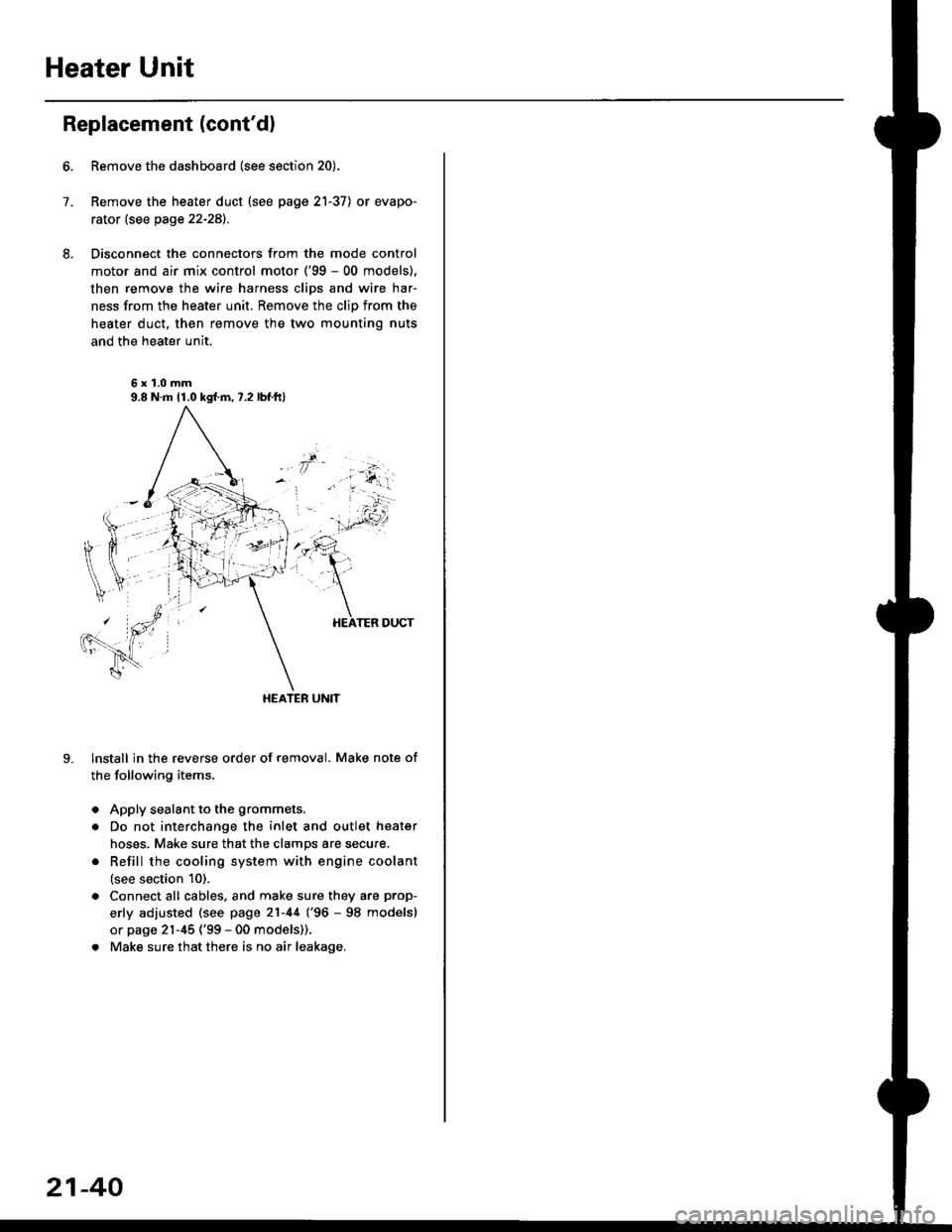
Heater Unit
Replacement (cont'dl
6.
7.
8.
9.
Remove the dashboard (see section 20).
Remove the heater duct (see page 21-37) or evapo-
rator (see page 22-28).
Disconnect the connectors from the mode control
motor and air mix control motor ('99 - 00 models),
then remove the wire harness clips and wire har-
ness from the heater unit. Remove the clip from the
heater duct, then remove the two mounting nuts
and the heater unit.
6x1.0mm9.8 N.m 11.0 kgl.m,7.2 lbf.ftl
HEATER UNIT
lnstall in the reverse order of removal. Make note of
the following items.
Apply sealant to the grommets.
Do not interchange the inlet and outlet heater
hoses. Make sure that the clamps are secure.
Refill the cooling system with engine coolant
(see section 10).
Connect all cables, and make sure they are prop-
erly adjusted (see page 21-44 (96 - 98 models)
or page 21-45 ('99 - 00 models)).
Make sure that there is no air leakage.
21-40