1996 HONDA CIVIC Timing
[x] Cancel search: TimingPage 59 of 2189
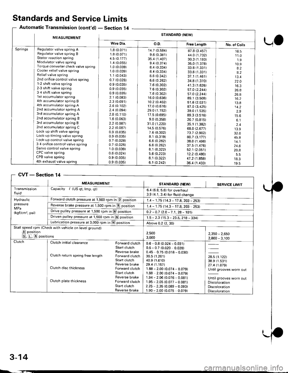
Standards and ServiceLimits
Section '14Automatic Transmission (cont'd)
UO
MEASUREMENTSTANDARD {NEW}
Wire Dia.o.D.Free LongthNo. ol CoilsHegulator valve spring ARegulato. valve spring BStator reaction springModulator valve springTorque convener check valve springCooler relief valve springRelief valve spring2nd oritice control valve spring1-2 shift valve spring2-3 sh ift valve spring3 4 shift valve spring'l st accumulator spring4th accumulator spring B4th accumulator spring A2nd accumulator spring A3rd accumulator spring A2nd accumulator spring B3rd acc!mulator spring B2nd accumulator spring CLock up shift valve springLock up timing valve springLock-up control valve spring3 4 ofifice control valve springServo control valve springCPC valve springCPB valve spring4th exhaust valve spring
Springs1.8 {0.071)1.8 {0.071)4.5 \O.117)1.4 (0.055)
1.0 10.039)1.0 (0.039)
1.1 (0.043)
0.7 (0.028)
0.9 (0.035)
0.9 (0.035)
0.9 (0.035)
2.1 (0.083)
2.3 (0.091)
2.610.102)2.4 (0.094)
2.8 (0.'110)
1.6 (0.063)
2.2 (0.087)
2.2 t0.041)0.9 (0.035)
0.9 (0.035)
0.7 (0.028)
0.7 (0.028)
1.0 (0.039)
0.6 (0.024)
0.9 {0.035)0.9 (0.035)
14.7 (0.584)
9.6 (0.381)
3s.4 (1.407)
9.4 (0.374)8.4 (0.334)
8.4 (0.334)
8.6 {0.342)6.6 (0.262)
7.6 (0.302)
7.6 (0.302)
7.6 (0.302)16.0 (0.636)10.2lo.402l17.0 {0.676)29.0 (1.152)
17.5 (0.6951
9.0 (0.358)
31.0 (1.220)
14.5 {0.576)7.6 (0.302)
8.1 (0.319)
6.610.262)6.6 (0.262)
8.1 (0.322)
5.6 (0.2231
8.1 10.322)6.1 10.242)
87.8 (3.457)
44.0 i.732l'30.3 (1.193)
35.0 {1.378)33.8 (1.331)
33.8 (1.331)
37.1 (1.461)
34.8 (1.370)
41.3 (1.626)
57.0 (2.2441
51 .0 \2.244189.1 {3.508)51.6 (2.031)
87.0 (3.425)
39.011.535)89.3 (3.516)
20.7 (0.815)
35.1 11.382)68.012.671173.7 12.902)80.7 (3.177)38.0 {1.496)37.5 fi.476)52.1 (2.051)
12.2 (0.480)
47.2 {1.858}36.4 {1.433)
16.511.01.910.94.24.213.422.016.326.826.a16.213.814.22.915.66.12.413.932.045.814.124.620.4
18.319.5
CVTSection 14
3-14
MEASUREMENTSTANDARD INEWISERVICE LIMITTransmissionfluidCapacity f {US qt, lmp. qt)6.4 {6.8, 5.6) for overhaul3.9 (4.1, 3.4) for fluid change
Hydraulicpressure
1kgflcm,, psi)
Forward clutch pressure at 1,500 rpm in E position1.4 - 1.15 114.3 - 11.A,203 - 2531Reverse brake pressure at 1,500 rpm in E position1.4 - 1.75 (14.3 11.8,203 2531Dr;ve pulley pressure at 1,500 rpm in E posrtrono.2 -0.7 12.0 -7.1,28- 1011Driven pulley pressure at 1,500 rpm in N positionr.5 - 2.3 115.3 - 23.5, 218 - 334)Lubrication pressure at 3,000 rpm in E posrtronAbove 0.212,30)Stall speed fpm (Check with vehicle on level ground)
E position
E, E, El positions2,5003,0002,350 - 2,6502,800 - 3, r00ClutchClutch initial clearance Forward clutchStart clutchReverse brakeClutch return spring free length Forward clutchStart clutchReverse brakeClutch disc thickness Forward clutchStart clutchReverse brakeClutch plate thickness Forward clutchSta rt clutchReverse brake
0.6 - 0.8 (0.024 - 0.031)0.5 - 0.7 (0.020 0.028)0.45 - 0.75 (0.018 - 0.030)30.5 {1.201)40.9 (1.610)
29.4 (1.157)
1.88 - 2.00 (0.074- 0.079)1.88 2.00 (0.074 - 0.079)1.94 - 2.06 (0.076 - 0.081)1.95 - 2.05 (0.077 -0.081)
2.25 2.35 (0.089 - 0.093)1.90 - 2.00 (0.075 0.079)
,*x.ar}38.9 (1.531)
27.411.019l'Until grooves worn out
Until grooves worn outDiscolorationDiscolorationDiscoloration
L.
Page 64 of 2189
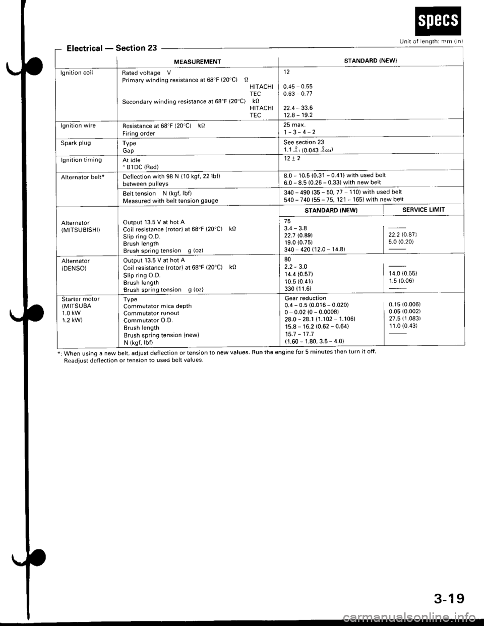
ElectricalSection 23
*: When using a new belt, adjust deflection or tension to new values. Run the engine for 5 minutes then turn it off
Readiust deflection or tension to used belt values
Unit of englh: mm {n)
MEASUREMENTSTANDARD {NEW}
lgnition coilRated voltage VPrimary winding resistance at 68'F (20'C) oHITACHITEC
Secondary winding resastance at 68'F 120"C) kOHITACHITEC
12
0.45 0.550.63 0.11
22.4 - 33.612.A - 19.2
lgnition wireResistance at 68'F (20'C) kf)
Firing order
25 max.1-3-4 2
Spark plugTypeGap
See section 231.1 3, (o.o€ -3*.)
lgnition timingAt idle' BTDC lRed)
Alternator belt+Deflection with 98 N (10 kgf,22lbf)between pulleys8.0 - 10.5 {0.31 - 0.41} with used belt
6.0 - 8.5 {0.26- 0.33)with new belt
Belt tension N (kgf, lbf)
Measured with belt tension gauge340 - 490 (35 - 50, 77 110) with used belt
540 - 740 (55 - 75, 121. 165)whh newbert
(MITSUBISHI)Output l3.5 V at hot ACoal resistance (rotor) at 68'F (20"C) kO
Slip rins O.D.Brush lengthBrush spring tension g (oz)
STANDARD INEWI SERVICE LIMIT
753.4-3.8 I -
Z2.j \0.A9) 22.2 \0.47)19.0 (0.75) 5.0 (0.20)
340 420 (12.0 14.8)
Alternator(DENSOiOutput '13.5 V at hot A
Coil resistance (rotor) at 68'F (20'C) k0
Slip ring O.D.Erush lengthBrush spring tension g (oz)
802.2 - 3.014.4 (0.57) | 14.0 (0.55)
10.5 (0.41) 1.5 (0.06)
330 {11.6)
Starter(MITSUEA
1.0 kw1.2 kW)
TvpeCommutator mica depthCommutator runoutCommutator O.D.Brush lengthBrush spring tension (new)
N (ksf, lbf)
Gear reduction0.4 - 0.5 (0.016 - 0.020) 0.15(0.006)
o o.o2 (o - 0.000e) | o.o5 (o.oo2)
28.0-28.1 (1.102 1.106) | 27.5(1.083)
15.8 - 16.2 10.62 - 0.64) 11.0 (0.43)
15.7 - 11 .1
{1.60 - 1.80, 3.5 - 4.0i
3-19
Page 112 of 2189
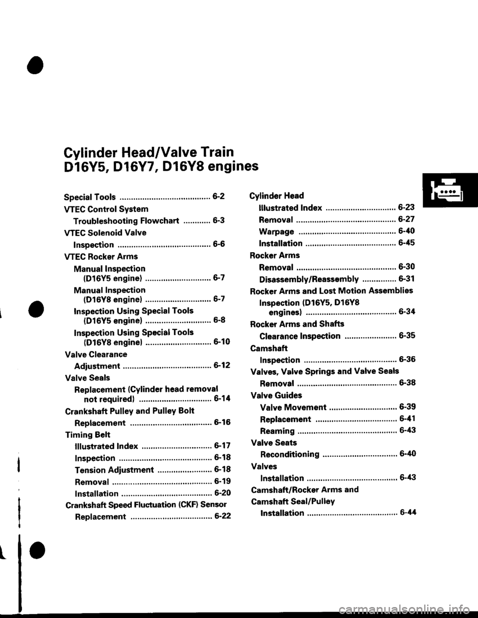
Cylinder Head/Valve Train
Dl6Y5, D16Y7, Dl6Y8 engines
Special Tools ............. G2
VTEC Control System
Troubleshooting Flowchart .........." 6-3
VTEG Solenoid Valve
Inspection ............" 6-6
VTEC Rocker Arms
Manual lnspection
(D16Y5 engine) ............................. 6-7
Manual Inspection
(D16Yg enginel ................'............ 6-7
Inspection Using Special Tools
{D16Y5 engine} .....................""'... 6-8
Inspection Using Special Tools
(D16Y8 engine) .........................'.'. 6-10
Valve Clearance
Adiustment ..."".....6-12
Valve Seals
Replacement (Cylinder head removal
not requiredl ................................ 6-1tl
Crankshaft Pulley and PulleY Bolt
Replacement ."...... &16
Timing Selt
lllustrated Index ............................... 6-17
Inspection .............. 6-18
Tension Adjustment ........................ 6- 1 I
Removal ......,,......... 6-19
lnstallation ............. 6-20
Crankshaft Speed Fluctuation (CKF) Sensor
Repf acement .........6'22
Cylinder Head
lllustrated Index ............................... 6-23
Removal ................. 6-27
Warpage ................ 6-40
lnstallation ............. 6-45
Rocker Arms
Removal ................. 6-30
Disassembly/Reassambly ............... 6-31
Rocker Arms and Lost Motion Assemblies
Inspection (D16Y5, D16Yg
enginesl "..........' 5-34
Rocker Arms and Shafts
Glearance Inspection ....................... 6-35
Camshaft
Inspection .............. 6-36
Valves, Valve Springs and Valve Seals
Removal ........""..... 6-38
Valve Guides
Valve Movement .............................. 6-39
Replacement .........6-41
Reaming .......'......'.' 6-43
Valve Seats
Reconditioning .'....6'40
Valves
lnstallation ............. 6-tt3
Camshaft/Rocker Arms and
Camshaft Seal/Pulley
lnstallation ............. 6-44
Page 119 of 2189
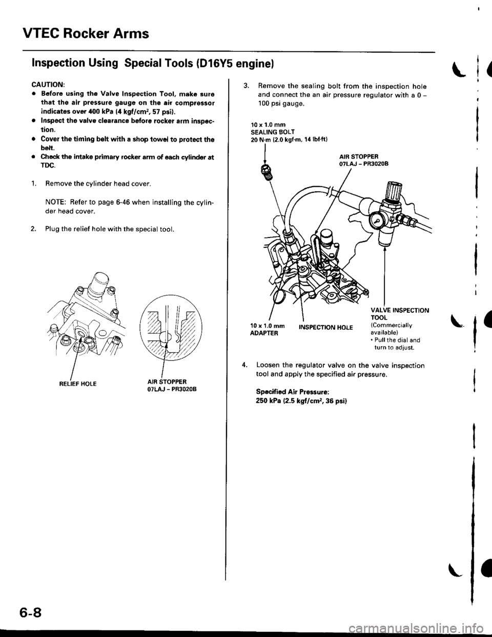
VTEC Rocker Arms
Inspection Using SpecialTools (Dl6Y5 enginel
CAUTION:
. Before using th6 Valve Inspection Tool, make 3ure
that ths air pressure gaugo on the air comptsssor
indicates over iloo kPa 14 kgf/cmr, 57 psi).
. Inspecl th6 valv€ clearance beforo rocker atm insDec"
tion,
'1.
Cover the timing belt with a shop towel to protect tho
belt.
Check ths intakg primaty rocker arm of each cylindqr atTDC.
Remove the cylinder head cover.
NOTE: Refer to page 6-46 when installing the cylin-
der head cover.
Plug the relief hole with the special tool.
YY
OTLAJ - PR3O2OB
(
3, Remove the sealing bolt from the inspection holeand connect the an air pressure regulator with a 0 -
100 psi gauge.
10 x 1.0 mmSEALING BOLT20 N.m {2.0 kgj'm. 14lblft}
l
I
'10 x 1.0 mmADAPTER;NSp€CTTONHOLE (Commercially
available)
l'Pullthe dial andturn to adlust,
Loosen the regulator valve on the valve inspection
tool and apply the specified air pressure.
Spocified Air Pressurei
250 kPa {2.5 kg,t/cm,,36 psi}
o-at
Page 120 of 2189
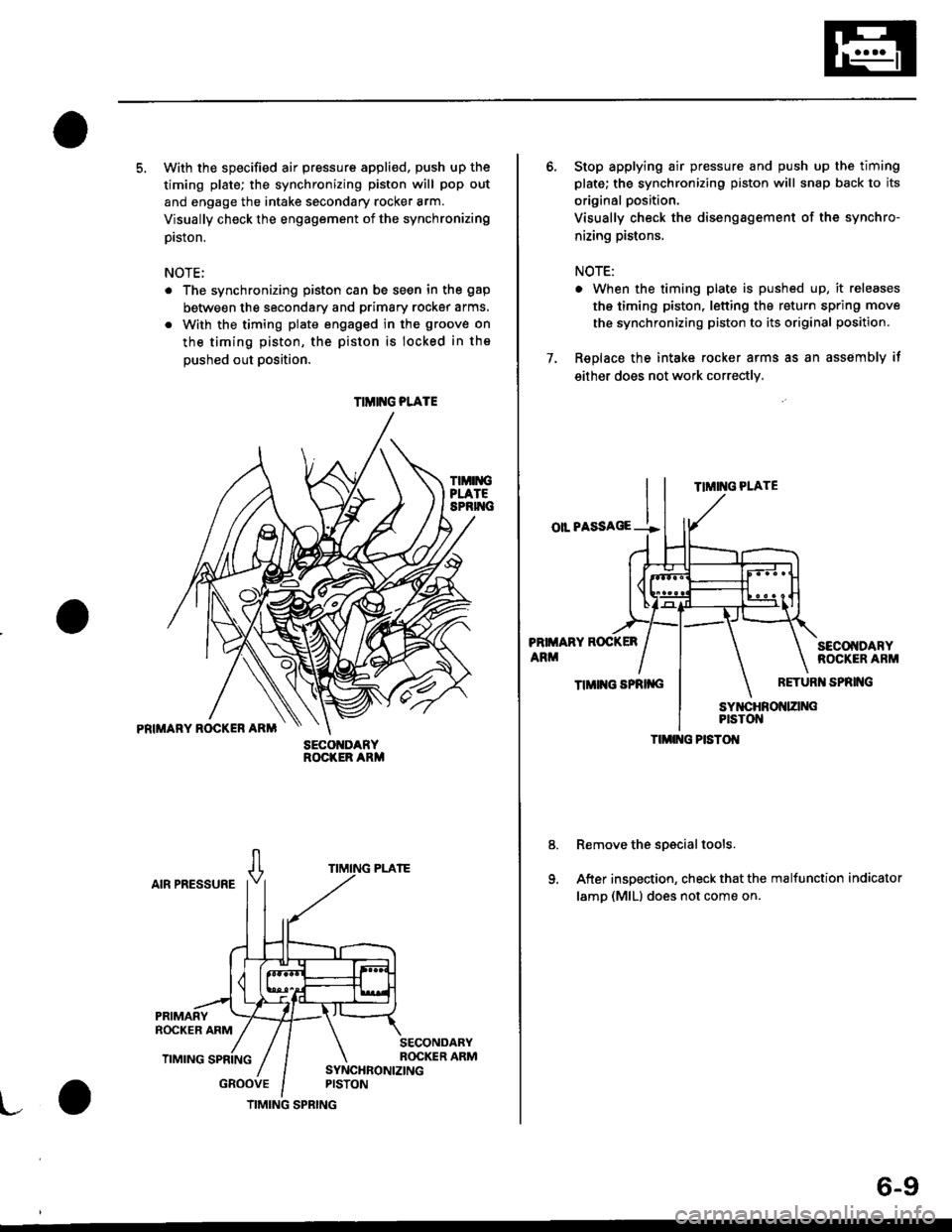
5. With the specified air pressure appli€d, push up the
timing plate; the synchronizing piston will pop out
and engage the intake secondary rocker arm.
Visually check the engagement of the synchronizing
prston.
NOTE;
The synchronizing piston can be seen in the gap
between the secondary and primary rocker arms,
With the timing plate engaged in the groove on
the timing piston, the piston is locked in the
oushed out Dosition.
TIMIiIGPLATESPRIT{C
PRIMARY ROCKER ARM
AIR PRESSURE
GROOVE
SECO DARYROCKER ARM
TIMIT{G PLATE
TIMING SPRING
6-9
6. Stop applying air pressure and push up the timing
plate; the synchronizing piston will snap back to its
original position.
Visually check the disengagement of the synchro-
nizing pistons.
NOTE:
. When the timing plate is pushed up, it releases
the timing piston, letting the return spring move
the synchronizing piston to its original position.
7. Replace the intake rocker arms as an assembly if
either does not work correctly,
TIMING PLATE
oll PASSAGE --!
PRIMARY ROCKER
ARMSECOI{DARYROCKER ARM
TIMII{G SPRII{GRETURI{ SPRING
Remove the spscial tools.
After inspection, check that the malfunction indicator
lamp (MlLl does not come on.
TIMI G PISTOI{
Page 121 of 2189
VTEC Rocker Arms
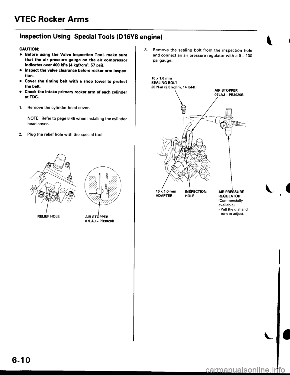
Inspection Using Special Tools (D16Y8 enginel
CAUTION:
o Before using the Valve Inspection Tool. mak6 surethat the air pressure gauge on the air comprsssor
indicates ovor 400 kPa {4 kgf/cm,, 57 psil.
. Inspect th6 valve clearanco before rockar arm inspec-
tion.
. Cov€r th€ timing belt with a shop towel to protect
the bolt.
. Check tho intake prima.y rockff arm of each cylindel
at TDC.
1.Remove the cylinder head cover.
NOTE: Refer to page 6-46 when installing the cylinder
neao cover,
Plug the relief hole with the specialtool.
OTLAJ - PR3O2OB
I,^ A IAo- tu
3. Remove the sealing bolt from the inspection hole
ancl connect an air pressure regulator with a 0 - 100psi gauge.
l0 x 1.0 mmSEALING EOLT20 N.m (2.0 kgf.m, 14 lbf.ft)
(AIR PRESSUREREGULATOR
{Commerciallyavailable). Pullthe dialandturn to adjust,
Page 127 of 2189
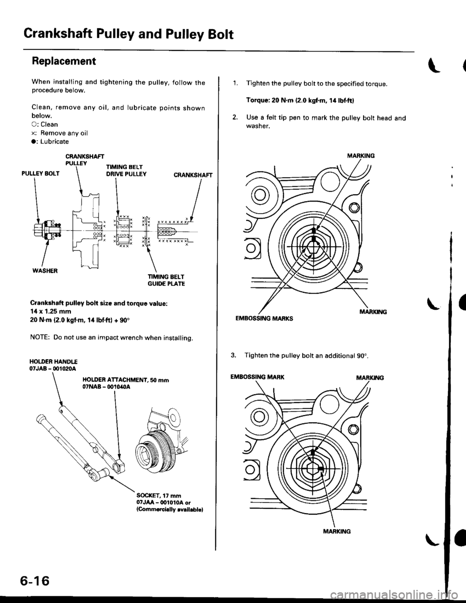
Crankshaft Pulley and Pulley Bolt
Replacement
When installing and tightening the pulley. follow theprocedure below,
Clean, remove any oil, and lubricate points shown
below.
O: Clean
x: Bemove any oil
a: Lubricate
TIMING BELTGUIOE PLATE
Crankhaft pulley bolt size and torque value:
14 x 1.25 mm
20 N.m {2.0 kgl.m, 14 lbf.ft) + 90'
NOTE: Do not use an impact wrench when installing.
HOI.I'ER HANDTI07JAB - 001020A
HOLDER ATTACHMENT. 50 mm07NAB - ootoilllA
S(rc(ET, 17 mm07JAA-lxtl010A or{Co.nm.rci.lly .v.il.bl.}
CRANKSHAFT
6-16
'1.Tighten the pulley bolt to the specified torque.
Torque: 20 N.m {2.0 kgf.m, 14 lbf'ft}
Use I felt tip pen to mark the pulley bolt head andwasher.
EMBOSSING MARKS
3. Tighten the pulley bolt an additional 90".
EMBOSSING MABKMARKING
\
MARKING
MARKING
I
Page 128 of 2189

Timing Belt
Illustrated lndex
NOTE:
. Refer to page 6-20 for how to position the crankshaft and pulley before installing the belt.
. Mark the direction of rotation on the belt before removing.
a Do not use the upper cover and lower cover for storing removed items,
. Clean the upper cover and lower cover before installing.
. Replace the ca mshaft seals and cra n kshaft sea ls if there is oil leakage.
. Refer to page 6-16 before installing the timing belt.
CYLINDER HEADCOVERReler to page 6-46when installing.
HEAD COVEB GASKETReplaco when l6akin9,domaged or deteriorated.Apply liquid gasket at
th€ lour corners of thetecessos.
d
@
TIMING BELTInspection, page 6-18Adjustment, page 6-18Removal, page 6-19Installation. page 6-20
I x 1.25 mm3t N.m {3.8 kgf'm, 27 lbfftl
Apply engine oilto the bolt
thleads.
CRANKSHAFT SPEED FI.UCTUATION
lcr(Fl sENsoRReplacement, Page 6-22
UPPER COVEB
lnstallwithsurface facing in.
TIMING BELTDRIVE PULLEYReplacement, page 6_16
6x1.0mm9.8 N'm 11.0 kgt m,7.2 tbf.ft)NUBBER SEALSReplace when damagedor deledorated.
LOWER COVER
FUBBERPLUG
CRANKSHAFT PULLEYReplacement, page 6'16
PULLEY BOLTlil x 1.25 mm20 N.m 12.0 kgt.m,14 lbt'ft) + 90"Replacement, page 6'16Do not us6 an impactwrench when installing.
x 1.0 mmBOLT o-RING10 x 1,25 mm Reolace.14 N.m {,1.5 kgt m, 33 lbt ftl
6x1.0mmt2 N.m 11.2 kgf'm,8.7 tbt f0
9.E N'm (1.0 kgt.m,?.2 tbf.ftl\.-,o
6-17