Page 1211 of 2189

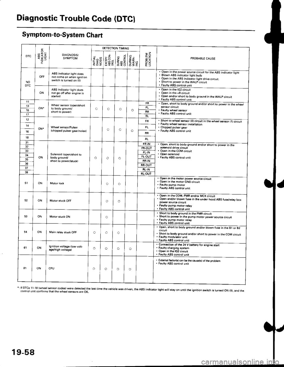
Diagnostic Trouble Code (DTCI
Symptom-to-System Chart
DTC
oH1=DIAGNOSIS/SYMPTOM
DETECTION TIMING
>=PNOBABLE CAUSEi.'sEV98€E
zr\9=6<_6
=t
6tz
NODTC
ABS indicator iighr doesnot com€ on when ignirionswrt.h is lu.ned on (ll)
, Open in the pow€. source circ!ir ror the ABS -.ndicato;l isht. Elown ABS indicalo.lighr butb' Open in rhe ABS indicaror tight drive cncuit.. Shori ro pow€r in theWALpcircuit. FaultyABS contrct!nit
ONABS indicator light doesnol90 oft 6frer engine isOpen in the lG2 circuitOpon in the +B circuirOp€n andlor short ro body ground jn the WALP circuitFaultv AAS coni.ol unnt1
oN.Wheel sensor (op€n/shortOooo13upen, snofiro bodyground and/or shodro power in rhe wh€61
Faulty ABS co.lrctunitllBL12
oN.(chipp€d pulser gea/noise)oao
Short to wh6sls€n6or (O)circuir in t'e.h;;Go-nso, trtcircutiFaulty whsel s€nsor insra|ation
Faulty ABS cont.olunir
I8
31
ONSolenoid (open/shon roaoa
Op.ni shon to bodyground and/o. shorrto powsr in rhe
op€n in lh6 coM circuit
Faulty ABS conlrclunit
32F8-OUTFL.IN3'lFT.OUTRF.IN88 OUT318t rN38RLOUT
ONoo
op€n in tho motor pow€..ourco circliaOp€n inih€ moro.cNOcircuit
Faulty ABS conrrol unit
52ONoo
Open in rh€ COM, PMR 6nd/o. MCKcircuirOp€n.n.Vor blown lus€ in the under hood AgS rusdretry box
Faufty pump moto. rotayfaulv ABS conlrolunit
53ONo
. Sho.tto bodygrou.d in the pMR circuit. Shon to powsr in tha puhp moror pow6rsource circu. r.urty pump motor.etay, FalltyABS contolunit
54ONooc
Open, rhorr ro bodygrcund and/or blown fus€ in the B1 or 82
Shonto body ground.n.Vor short to powor in rhe COM circuitFaulty modul.tor unnFaulty ABS controt unit
ONlgnition voltage (low vott-oooo
. Connection ot the24 V bariorv tor enqins starr. Faurtycharoins system. Op€n in th6lG2 circuit. Fa!lly ABS contrcl unil
81ONCPUoooo
E {€rml facior{sl en bs rhe ouse{sl ot |he probtemF.ulty ABS conrrot unit
r: It DTcs 1 1 18 {wheel sensor codes) wore del*ted the lasr time the v6h cls wEs d riv€n, rhe a8s indicator tight wi
stay on u ntit lh6 ignition swirch is rurn6d oN t), and theconnorunit contnms rhat rhe wheet sensoB . rc OK,
19-58
Page 1572 of 2189
lgnition System
Component Location Index
IGNITION TIMING CONTROL SYSTEM
. Troubleshooting, section 11
. ldle speed Inspection/Adjustment. section 11
. Inspection and Setting, page 23-105
SERVICE CHECK CONNECTOR {2P}Iwiie colors: 8RN and BLKI
TEST TACI{OMETER CONNECTOB
IGNITION WIRESlnspection and Test, page 23-110
PLUGSInspection, page 23 1 11
Replacement, page 23'106Overhaul, page 23-107lgnition Coil Test, page 23'110lgnition Control Module llCM)Input Test, page 23-109
23-102
Page 1575 of 2189

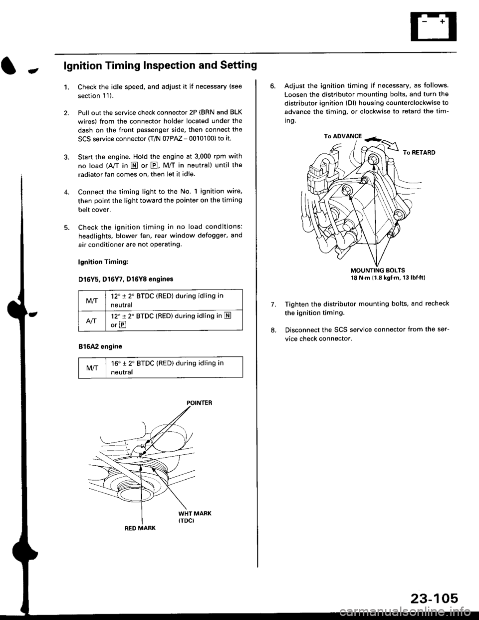
-lgnition Timing Inspection and Setting
1.Check the idle speed, and adjust it it necessary (see
section 'l '1 ).
Pull out the service check connector 2P (BRN and BLK
wires) from the connector holder located under the
dash on the front passenger side, then connect the
SCS service connector (T/N 07PAZ - 0010'100) to it.
Start the engine. Hold the engine at 3.000 rpm with
no load {A,/T in E or E. M/T in neutral) until the
radiator fan comes on, then let it idle.
Connect the timing light to the No. 1 ignition wire,
then point the light toward the pointer on the timing
belt cover.
Check the ignition timing in no load conditions:
headlights. blower fan, rear window defogger, and
air conditioner are not operating.
lgnhion Timing:
D15Y5. D16Y7, Dl6Yg engines
816A2 engine
MIT16" 12' BTDC (RED) during idling in
neutral
M/T12't 2" BTDC (RED) during idling in
neutral
l2'r 2" BTDC {RED) during idling in S
orE
POINTEB
RED MARK
23-105
ro ADVANCE -<;,
6. Adjust the ignition timing if necessary, as follows.
Loosen the distributor mounting bolts. and turn the
distributor ignition (Dl) housing counterclockwise to
advance the timing, or clockwise to retard the tim-
ing.
MOUNTING BOLTS18 N'm (1.8 kgfm, 13lblftl
Tighten the distributor mounting bolts, and recheck
the ignition timing.
Disconnect the SCS service connector from the ser-
vice check connector.
7.
Page 1576 of 2189

lgnition System
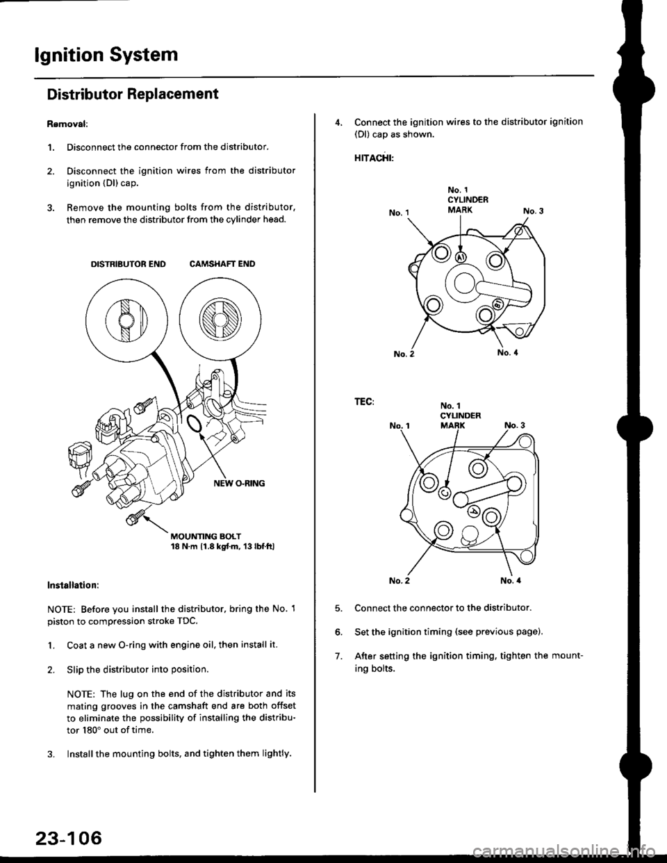
Distributor Replacement
Removal:
1. Disconnect the connector from the distributor.
2. Disconnect the ignition wires from the distributor
ignition {Dl) cap.
3. Remove the mounting bolts from the distributor,
then remove the distributor from the cylinder head.
DISTRIBUTOR END CAMSHAFT END
MOUNTING BOLT18 N.m 11.8 kgtm, 13lbf.ltl
lnstallation:
NOTE: Before you install the distributor. bring the No. 1
piston to compression stroke TDC.
1. Coat a new O-ring with engine oil, then install it.
2. Slip the distributor into position
NOTE: The lug on the end of the distributor and its
mating grooves in the camshaft end are both offset
to eliminate the possibility of installing the distribu-
tor 180" out of time.
3. Installthe mounting bolts, and tighten them lightly.
23-106
4, Connect the ignition wires to the distributor ignition
(Dl) cap as shown.
rracfit'
No. 1CYLINDERMARK
No. 1CYLINDER
TEG:
5.
6.
7.
No. 2No. a
Connect the connector to the distributor.
Set the ignition timing (see previous page).
After setting the ignition timing, tighten the mount-
ing bolts.
Page 1581 of 2189

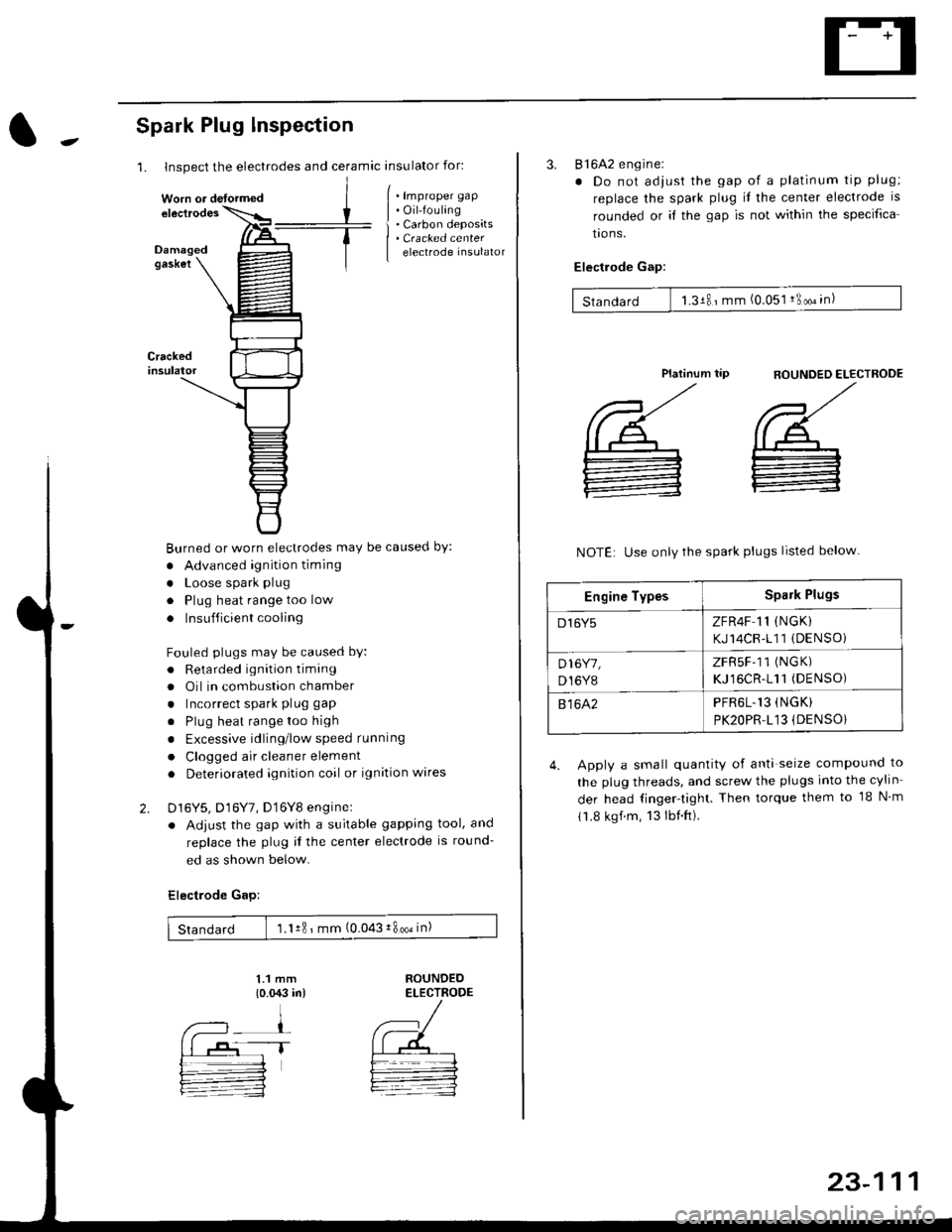
1. Inspect the electrodes and ceramic insulator for:
Spark Plug lnspection
Crackedinsulator
2.
[ . t.p,op", grp
| . Oil-fouling
i . Carbon deposits
| . Cracked center
I electrode insulator
Burned or worn electrodes may be causecl by:
. Advanced ignition timing
. Loose spark plug
. Plug heat range too low
. Insufficient cooling
Fouled plugs may be caused bY:
. Retarded ignition timang
. Oil in combustion chamber
. Incorrect spark plug gap
. Plug heat rangetoo high
. Excessive idling/low speed running
. Clogged air cleaner element
. Deteriorated ignition coil or ignition wares
D16Y5, D16Y7, D'16Y8 enginel
. Adjust the gap with a suitable gapping tool, and
replace the plug il the center electrode is round-
ed as shown below.
Electrode Gap:
1.1 mm
{o.{X:l in)ROUNDEDELECTRODE
Standard 1.1r8 ' mm (0.043i800oin)
Worn or detormed
1T
23-111
3. 816A2 engine:
. Do not adjust the gap of a platinum tip plug;
replace the spark plug il the center electrode is
rounded or it the gap is not within the specifica
tro ns.
Electlode Gap:
Standard 1.3181mm (0.051 !3oo" in)
flOUNDED ELECTROOE
',/
@_
:
Platinum tip
NOTE: Use only the spark plugs listed below
4. Apply a small quantity of anti seize compound to
the plug threads, and screw the plugs into the cylin
der head finger-tight. Then torque them to 18 N m
11.8 kgf.m, 13lbnft).
Engine TypesSpark Plugs
D16Y5ZFR4F 11 (NGK)
KJ14CR-111 (DENSOi
D16Y7,
D,I6Y8
ZFRSF-11 (NGK)
KJ16CR-111(DENSO)
81642PFR6L.13 (NGK)
PK2OPR.L13 (DENSO}