Page 626 of 2189
Special Tools
SpecialTools
I
I
I
./
Ref. No. Tool NumberD€scriptionOty I Remark
o
@
o-@
@
o
@
@
@
o
@
07GAJ - PG20110
07GAJ - PG20l30
07JAD - PH80l0'1
07736 - A010004
07746 - 0010300
07746 - 0010400
07746 - 0030100
07746 - 0030300
07746 - 0030400
07746 - 0041100
07749 - 0010000
07947 - SD90200
Mainshaft Holder
Mainshaft Base
Driver Attachment
Adjustable Bearing Puller,25 - 40 mm
Attachment, 42 x 47 mm
Attachment, 52 x 55 mm
Driver, 40 mm LD.
Attachment, 30 mm LD.
Attachment, 35 mm LD.
Pilot, 28 mm
Hand le
Driver Attachment
I
1
1
1
I
1'l
I
1
1
1'I
13-90
13-90
13-96
13-86, 87
13-86
13-86, 87
13-73,79,83,84
13-73,19
13-73,79
13-86
13-86,87,96
13-96* Must be used with commercially-available 3/8,,-16 Slide Hammer.
o
aol@(t4^
Page 630 of 2189
Transmission Assembly
Removal(cont'd)
14. Remove the driveshafts and the intermediate shaft(see section 16).
NOTE: Coat all precision the finished surfaces with
clean engine oil or grease. Tie plastic bags over the
driveshaft ends,
Remove the bolt, then disconnect the change elden-
sion.
Remove the clip and the spring pin, then disconnectthe change rod.
8x22mmSPRING PINCLIP Replace.
15.
13-50
17. Remove the front and the rear engine stiffensrs.
18. Remove the clutch cover.
CLUTCH COVER
6x1.0mm12 N.m (1.2 kg{.m,9 tbf.ftl
x 'l .25 mm
tJ
24 N.m {2.4 kgt m,17 rbt ftl
Page 653 of 2189

Reassembly
CAUTION:
. Press the 3rd/4th and the 5th synchro hubs on the
mainshaft without lubrication.
o When installing the 3rd/,lth and the sth synchro
hubs, support the mainshaft on steel blocks, and
installthe synchro hubs using a prsss.
. Install the 3rd/4th and the sth synchro hubs with a
maximum plessur€ of 19.6 kN (2,000 kg, 14,466 lbl.
NOTE: Refer to page 13-67 for reassembly sequence.
1, Support 2nd gear on steel blocks, then install the
3rd/4th synchro hub using the special tools and a
press, as snown.
NOTE:
. After installing. check the operation of the
3rd/4th synchro sleeve and hub.
. Assemble the 3rd/4th synchro hub and sleeve
together betore installing them on the mainshaft.
Closed end
3RD/4THSYNCHRO HU3DBIVER, 10 mm l.O.07746 - 00301U)
/ lrrlcHlileNr. ss .- t.o.07746 - 0030,100
l.
3RD/{THSYNCHROSLEEVE
2ND GEAR
2. Install the sth synchro hub using the special tools
and a press as snown.
DRIVER, {0 mm l.O.07746 - 0030100
ATTACHMENT,35 mm LD.
sTH SYNCHRO HUB
07716 - 0030,100
3. Install the angular ball bearing using the special
tools and a press as shown.
PRESS
+
DRIVER, 40 mm LD.0?7a6 - It030100
Page 659 of 2189
9. Support the countershaft on a steel block, and
install 4th gear using the special tools and a press.
as 5nown.
ATTACHMENT,35 mm LD.07746 - 0030400
Support the countershaft on a steel block, and
install 5th gear using the special tools and a press,
as shown.
ATTACHMENT, 30 mm I,D,07746 - 0030300
10.
\
'1'1. Install the needle bearing, then install the ball bear-
ing using the special tools and a press as shown.
PRESSDRIVER,40 mm LD.07746 - 0030100
ATTACHMENT,30 mm LD.07746 - 0030300
J.-12.Securely clamp the countershaft assembly in a
bench vise with wood blocks.
lnstall the spring washer, tighten the locknut, then
stake the locknut tab into the groove.
LOCKNUT
108- 0- 108N.m 111.0- 0- 11.0kgt.m,
80+ 0* 80 lbf'ftl
WOOD BLOCKS
13-79
Page 666 of 2189
Clutch Housing Bearing
Replacement
Mainshaft:
L Remove the ball bearing using the special tools asshown.
3/81_ 16 SLIDE HAMMER{commercially available)
ADJUSTAELE BEARINGPULLER, 25 - 40 mm07736 - A01000A
2. Remove the oil seal from the clutch housino.
13-86
CLUTCH HOUSING
BALL BEARING
(
3. Drive the new oil seal into the clutch housing usingthe special tools as shown.
HANOLE07749 - 0010000
ATTACHMENT, 42 x 47 mm07746 - 0010300
4.
OIL S€ALReplace.
Drive the ball bearing into the clutch housing using
the specialtools as shown.
HANDLE07749 - 0010000ATTACHMENT, 52 x 55 mm07746 - 0010il{)0
PILOT, 28 mm07746 - 0041100
Page 667 of 2189
Countershaft:
1. Bend the tab on the lock washer down, then remove
the bolt and bearing retainer plate.
BEARING RETAINER PLATE
cLutcH tlouslNG
Remove the needle bearing using the special tools
as shown, then remove the oil guide plate'
3/8' - 16 SLIOE HAMMER(CommerciallY available)
^ LOCK WASHERg Reolace.
d---""-
t
ADJUSTABLE BEARING
PULLER,25 - {o mm07736 - Aolmo A
3. Position the oil guide plate and new needle bearing
in the bore of the ctutch housing, then drive in the
needle bearing using the special tools as shown
NOTE: Position the needle bearing with the oil hole
facing up.
NEEDLE
OIL HOLE
NEEDLEBEARING
Install the bearing retainer plate and new lock wash-
er, then bend the tab against the bolt head'
8x10mm15 N'm (1.5 kgt'm, rl |bt'ft)
LOCKWASHERReplace.
13-47
Page 680 of 2189

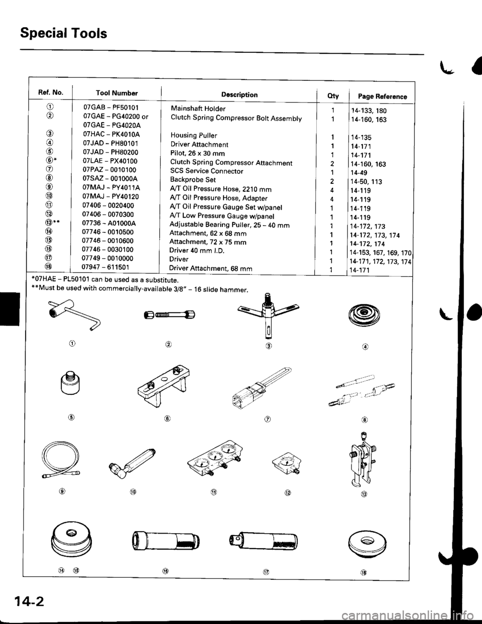
Special Tools
l.- a
Ref. No. Tool Number
o,6'\
€)
@)
@-
@
@
o
@
@
@
@..
@
@
@
@
@
07GAB - PF50101
07GAE - PG40200 or
OTGAE - PG4O2OA
07HAC - PK4010A
07JAD - PH80101
07JAD - PH80200
07LAE - PX40100
07PM - 0010100
07sM - 0010004
OTMAJ - PY4O1 1A
07MAJ - PY40120
07406 - 0020400
07406 - 0070300
07736 - A010004
07746 - 0010500
07746 - 0010600
07746 - 0030100
07749 - 0010000
07947 - 611501
Mainshaft Holder
Clutch Spring Compressor Bolt Assembly
Housing Puller
Driver Attachment
Pilot, 26 x 30 mm
Clutch Spring Compresso. Attachmenr
SCS Service Connector
Backprobe Set
IVT Oil Pressure Hose, 2210 mmAy'T Oil Pressure Hose, Adapter
Ay'T Oil Pressure Gauge Set dpanelA,/T Low Pressure Gauge WpanelAdjustable Bearing Pulter, 25 - 40 mmAftachment, 62 x 68 mm
Aftachment, 72 x 75 mmDriver 40 mm l.D.
Driver
Driver Attachment, 68 mm
I
1
1
1
I
1,l
'l
1
I
1
1
14-133, 180
14-160, 163
14-135
14-171
14-'�t7'l
14-160, 163
14-49
14-50, 113
r4-119
14- 1 19
14-119'14-1 19
14-172,173
14-172,'t73,114
14-172,174
14-153, 167. 169, 170
1+17 1 , 17 2, 173, 17
14-'t7'l
4
w
@o
*07HAE - P150101 can be used as a substitute.**Must be used with commercially-available 3/8,, _ 16 slide
E-E
@
@@
hammer.
=k
lalg
€)
ry
o
e
@
o
----a\\<-t-'- /\26
@@
@@@
aL
14-2
Page 682 of 2189

Description
(cont'dl
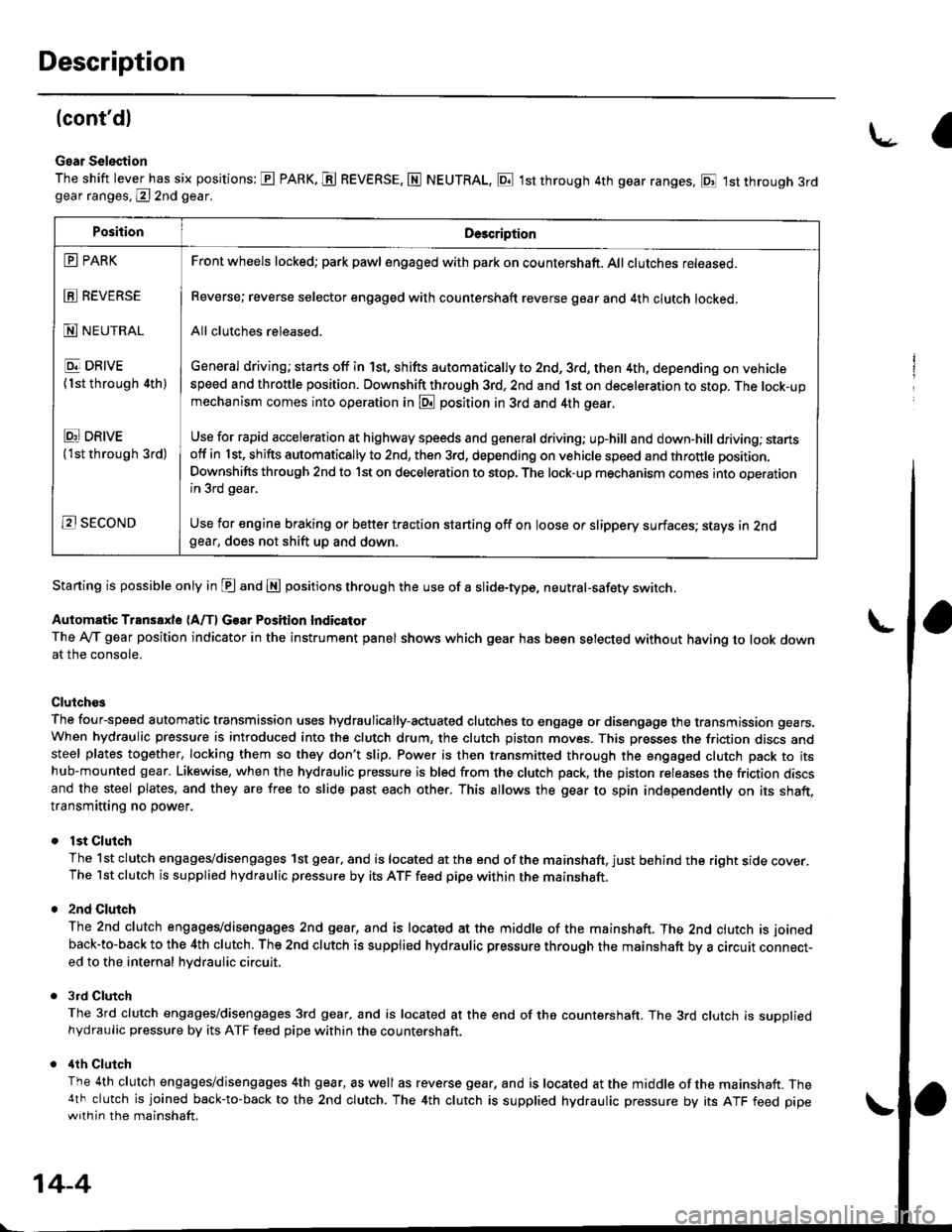
Gear Selection
The shift lever has six positions: E PARK. E REVERSE, N NEUTRAL, E 1st through 4th gear ranges, E 1st through 3rdgear ranges, @ 2nd gear.
Starting is possible only in E and E positions through the use of a slide-type, neutral-safety switch.
Automatic Transaxle (A/f, Gear Position Indicator
The Ay'T gear position indicator in the instrument panel shows which gear has been selected without having to look downat the console.
Clutch€s
The four-speed automatic transmission uses hydraulically-actuated clutches to engage or disengage the transmission gears.When hydraulic pressure is introduced into the clutch drum, the clutch piston moves. This presses the friction discs andsteel plates together, locking them so they don't slip. Power is then transmitted through the engaged clutch pack to itshub-mounted gear. Likewise, when the hydraulic pressure is bled from the clutch pack, the piston releases the friction discsand the steel plates, and they are free to slide past each other. This allows the gear to spin independently on its shaft,transmitting no power.
lst Clutch
The 1st clutch engages/disengages 1st gear, and is located at the end of the mainshaft, just behind the right sroe cover.The 1st clutch is supplied hydraulic pressure by its ATF feed pipe within the mainshaft.
2nd Clulch
The 2nd clutch engagegdisengages 2nd gear, and is located at the middle of the mainshaft. The 2nd clutch is joined
back-to-back to the 4th clutch. The 2nd clutch is supplied hydraulic pressure through the mainshaft by a circutr connect-ed to the internal hvdraulic circuit,
3rd Clutch
The 3rd clutch engages/disengages 3rd gear, and is located at the end of the countershaft. The 3rd clutch is suooliedhydraulic pressure by its ATF feed pipe within the countershaft.
ilth Clutch
The 4th clutch engages/disengages 4th gear, as well as reverse gear, and is located at the middle of the mainshaft. The4th clutch is joined back-to-back to the 2nd clutch. The 4th clutch is supplied hydraulic pressure by its ATF feed pipewith in the mainshaft.
\-a
PositionDe3cription
E PARK
E REVERSE
N NEUTRAL
E DRIVE
{1st through 4th)
Ei DRtvE('lst through 3rd)
B SECOND
Front wheels locked; park pawl engaged with pa* on countershaft. All clutches released.
Reverse; reverse selector engaged with countershaft reverse gear and 4th clutch locked.
All clutches released.
General driving; starts off in 1st, shifts automatically to 2nd, 3rd, then 4th, depending on vehiclespeed and throttle position. Downshift through 3rd, 2nd and 1st on deceleration to stop. The lock-upmechanism comes into operation in @ position in 3rd and 4th gear.
Use for rapid acceleration at highway speeds and general driving; up-hill and down,hill dfiving; stansotf in 1st, shifts automatically to 2nd, then 3rd, depending on vehicle speed and throttle position.
Downshifts through 2nd to lst on deceleration to stop. The lock-up mechanism comes into operationin 3rd gear,
Use for engine braking or better traction starting off on loose or slippery surfaces; stays in 2ndgear, does not shift up and down.
14-4