Page 204 of 2189
Flywheel and Drive Plate
Replacement
Manual Transmission:
816A2 engine:
Remove the eight flywheel bolts, then separate the fly-
wheel from the crankshaft flange. After installation'
tiohten the bolts in the sequence shown
RING GEAR HOLDER "-i
OTLAB PVOOlOO
D16Y5, D16Y7, D16Y8 engines:
Remove the six flywheel bolts, then separate the flywheel
from the crankshaft flange. After installation, tighten the
bolts in a crisscross Pattern.
RING GEABInspect ring gear
teeth lor wear or
damage.
RING GEARInspect ring gear
teeth lor wear orteetn lor wea( or /danase. ,///.'
12 x 1.0 mm103 N.m(10.5 kgf.m, 76 lbf.tt)
12 x 1.o mm1 18 N,m(12.0 kgI.m, 87 lbf.ftl
L
rurS;u'.\
$..3s'
Automatic Transmission:
Remove the six drive plate bolts, then separate the drive
olate from the crankshaft flange. Atter installation, tighten
the bolts in a crisscross Pattern.
t7.5 kgl.m, 54 lbl'ltl
12 x 1.0 mm74 N.m
7-7
Page 210 of 2189

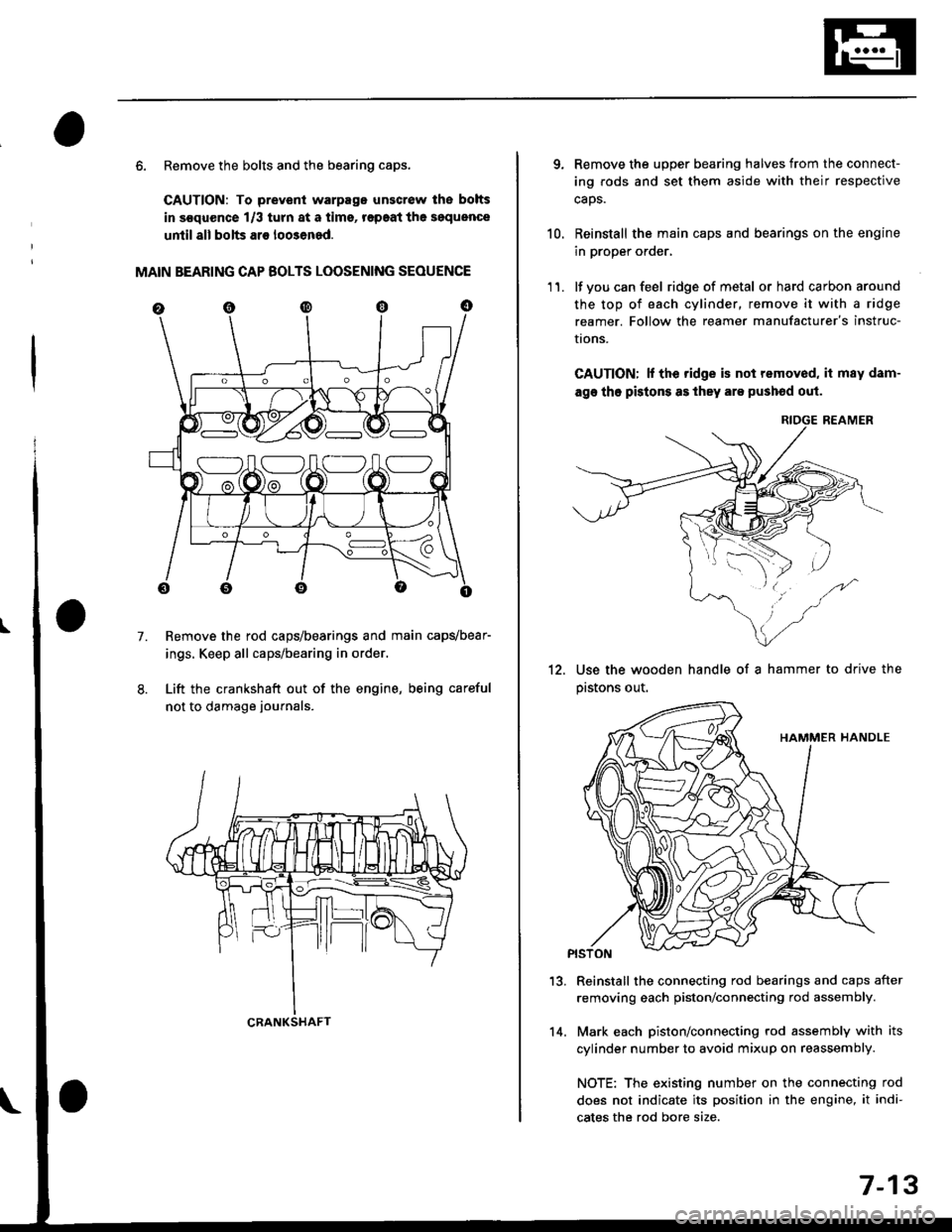
6. Remove the bolts and the bearing caps.
CAUTION: To prevenl warpago unscrow lhe bolts
in s€quence 1/3 turn at a tims, r€paat the soquence
until all bolts ar€ loo3ened.
MAIN BEARING CAP BOLTS LOOSENING SEOUENCE
Remove the rod caps/bearings and main capvbear-
ings. Keep all caps/bearing in order.
Lift the crankshaft out of the engine, being careful
not to damage journals.
7.
S:_]ILOJLOAO
CRANKSHAFT14.
7-13
qRemove the upper bearing halves from the connect-
ing rods and set them aside with their respective
caos.
Reinstall the main caps and bearings on the engine
in proper order,
lf you can feel ridge of metal or hard carbon around
the top of each cylinder, remove it with a ridge
reamer. Follow the reamer manufacturer's instruc-
I|ons.
CAUTION; lf the ridge is not removed, it may dam-
age tho pistons as they are pushod out.
RIOGE REAMER
10.
11.
12.Use the wooden handle of a hammer to drive the
pastons out.
13.Reinstall the connecting rod bearings and caps after
removing each piston/connecting rod assembly.
Mark each piston/connecting rod assembly with its
cylinder number to avoid mixup on reassembly.
NOTE: The existing number on the connecting rod
does not indicate its position in the engine, it indi-
cates the rod bore size.
Page 214 of 2189

Cylinder BlockPiston Pins
Bore Honing
1.Measure cylinder bores as shown on page 7-16. lf the
block is to be reused, hone the cylinders and remea-
sure the bores.
Hone cylinder bores with honing oil 8nd a fine (400
grit) stone in a 60 degree cross-hatch pattern.
NOTE:
. Use only a rigid hone with 400 grit or finer stone
such as Sunnen, Ammco, or equivalent.
. Do not use stones lhat are worn or broken.
When honing is complete, thoroughly clean the
engine block of all metal particles. Wash the cylin-
der bores with hot soapY water, then dry and oil
immediately to prevent rusting.
NOTE: Never use solvent. it will only redistribute the
grit on the cylinder walls.
lf scoring or scratches are still present in cylinder
bores after honing to the service limit, rebore the
cylinder block.
NOTE: Some light vertical scoring and scratching is
acceptable if it is not deep enough to catch your fin-
gernail and does not run the full length of the bore.
CYLINOES BLOCK
CYLINDER
NOTE:
. After honing, clean the cylinder thoroughly with
soapy warer.
. Onlv a scored or scratched cylinder bore must be
noneo.
Removal
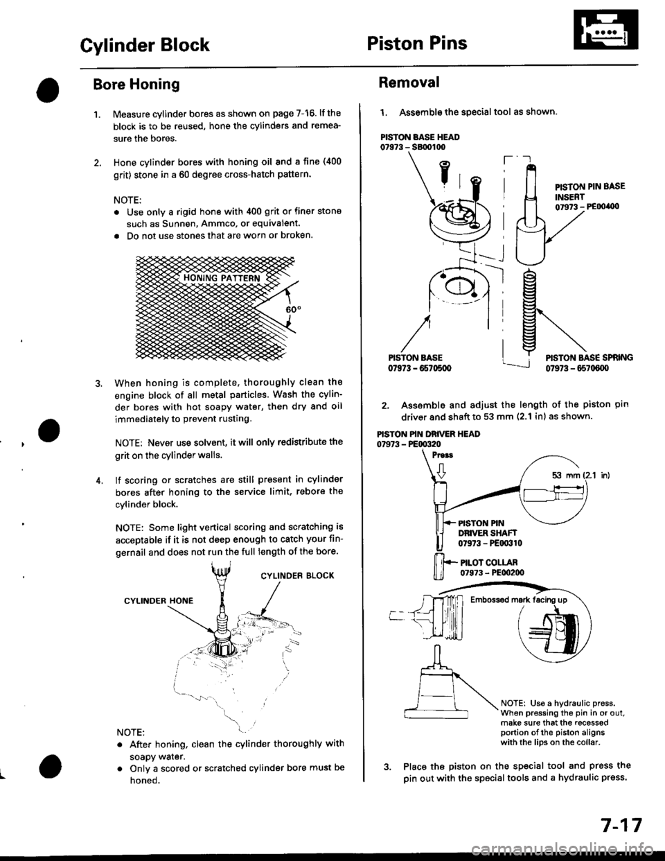
l. Assemble the special tool as shown.
PISTON BASE HEAD07973 - SBtx)too
ft
PISTON PIN BASE
INSERT01973 - PE00'0)
ptn
NOTEi Us6 a hydraulic press.When pressing the pin in or out.make sure that the recesssdportion of the piston alignswith the lips on the collar.
rg
g\
lj*N*,""
2. Assemble and adjust the length of the piston
driver and shaft to 53 mm (2.1 inl as shown.
PISTON PIN DRIVER HEAD07973 - PE00320
Proat
0
PISTON PINDRIVER SHAFT0t973 - PEqr310
PILOT COLLAR07973 - PE00200
3. Place the piston on the sp€cial tool and press the
pin out with the special tools and a hydraulic press.
Emboss6d mark facing up
7-17
Page 215 of 2189

Connecting RodsPiston Pins
Selection
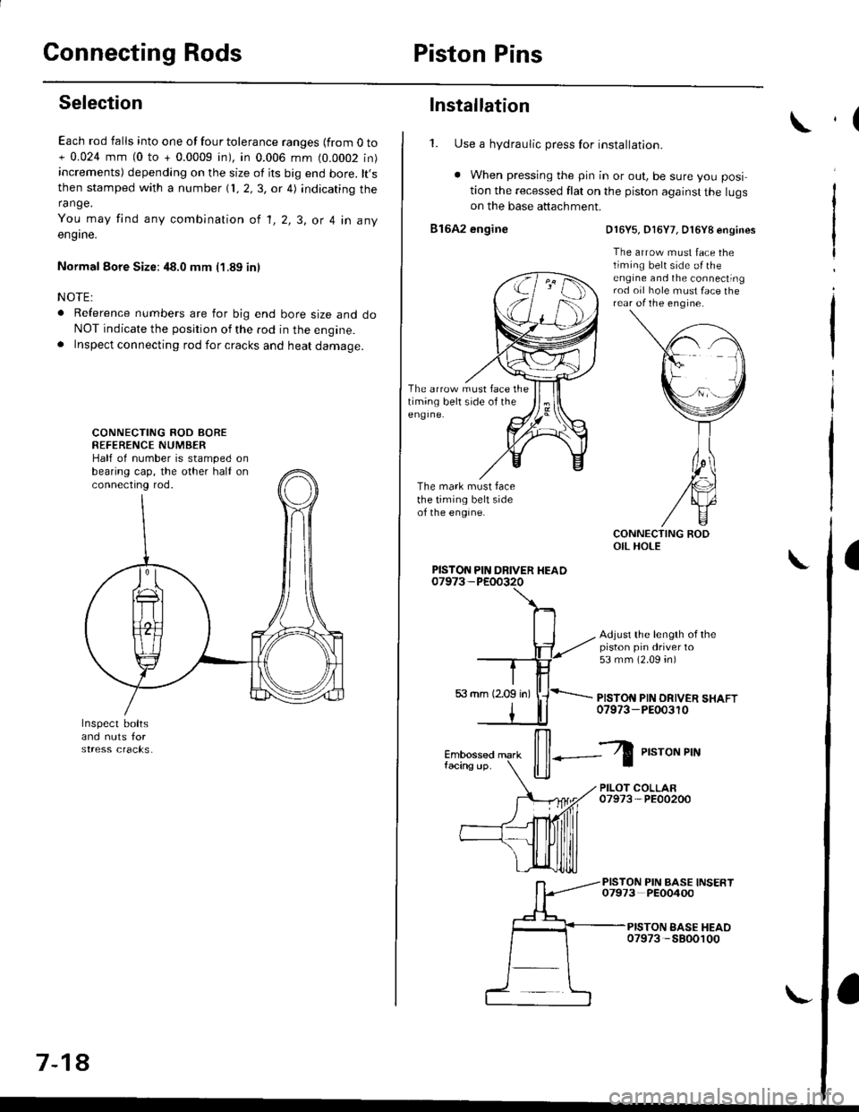
Each rod falls into one of four tolerance ranges {from O to+ 0.024 mm (0 to + 0.0009 in), in 0.006 mm (0.0002 in)increments) depending on the size of its big end bore. lt,sthen stamped with a number {1, 2,3, or 4) indicating therange.
You may find any combination ot l, 2, 3, or 4 in any
engrne.
Normal Eore Size: 48.0 mm (1.89 in)
NOTE:
o Reference numbers are for big end bore size and doNOT indicate the position of the rod in the engine.. Inspect connecting rod for cracks and heat damage.
CONNECTING ROD AOREREFERENCE NUMBERHalf of number is stamped onbearing cap, the other half onconnectrng rod.
7-18
Installation
1. Use a hydraulic press for installation.
. When pressing the pin in or out, be sure you posi
tion the recessed flat on the piston against the lugson the base attachment.
816A2 engine
The arrow must face thetiming belt side of theeng Ine.
The mark must facethe timing belt sideof the engine.
D16Y5, D16Y7, O16Y8 engines
The arrow must face thetiming belt side o{ theengine and the connectingrod oil hole must face therear of the engine.
Adjust the length of thepiston pin driver to53 mm (2.09 4n)
PISTON PIN DRIVER SHAFT07973-PEOo3r0
PISTON PIN DRIVER HEAD
il--Z
P,"roNPrN
PILOT COLLAR07973-PE00200
PISTON PIN BASE INSERT07973 PEO0400
PISTON EASE HEAO07973 -5800100
,(
a
Page 219 of 2189
Piston RingsCrankshaft Oil Seal
Alignment (cont'dl
TOP RING ---.>
SECOND RING >
MARK
,a-)
/\_4
o,.r^o( qffi<--sPACER
\Z-.
v
Rotate the rings in their grooves to make sure theydo not bind.
Position the ring end gaps as shown:
DO NOT position any ring gapat piston thrust surfaces.
DO NOT position any ring gapin line with the piston pin hole.OIL RING GAP
SECOND RING GAP
Approx.90
TOP RING GAP
7-22
Installation
The seal surface on the block should be dry.Apply a light coat of oil to the c.ankshaft and tothe lip of the seal.
1. Drive the crankshaft oil seal squarely into the right
side cover using the special tools.
HANDLE DRIVER07749 0010000
seal with thepan number sidefacing out.
Confirm that the clearance is equal all the way
around with a feeler gauge.
Clearance:0.5 - 0.8 mm (0.02 - 0.03 inl
NOTE: Refer to page 8-14 for installation of the oilpumo side crankshaft oil seal.
,(
\
Page 226 of 2189
Oil Seals
lnstallation
NOTE:
. Engine removal is not required.
. The crankshaft oil seal housing should be dry.
Apply a light coat of grease to the crankshaft and to
the lips of the seals.
1. Using the special tool, drive in the timing pulley-
end seal until the driver bottoms against the oil
pump.
When the seal is in place, clean any excess grease
off the crankshaft and check that the oil seal lip is
not distorted.
07947 -S800200
lnstall seal with thepart number sadefacing out.
I
2. Measure the flvwheel-end seal thickness and the oil
seal housing depth. Using the special tool. drive the
flywheel-end seal into the rear cover to the point
where the clearance between the bottom of the oil
seal and the right side cover is 0.5 - 0.8 mm (0.02 -
0.03 in) (see page 7-23).
NOTE: Align the hole in the driver attachment with
the Din on the crankshaft.
DRIVER ATTACHMENT0794a-s800101lnslall seal with thepart number sidefacing out.
DRIVER07749-0010000
7 -29
Page 239 of 2189

4.
Removal/lnspection/lnstallation
2.
3.
1.
5.
6.
1.
8.
Drain the engine oil.
Turn the crankshaft and align the white groove on
the crankshaft pulley with the pointer on the lower
cover.
Remove the cylinder head cover and upper cover'
Remove the power steering pump belt, air condi-
tioner beit and the alternator belt
Remove the crankshaft pulley and remove the lower
cover.
Remove the timing belt.
Remove the drive pulley.
Remove the oil pan and oil screen.
O.RINGReplaceOOWEL PIN
OIL SCREEN
9. Remove the oil PumP.
!'a
10.Remove the screws from the pump housing, then
separate the housing and cover'
Check the inner-to-outer rotor radial clearance on
the pump rotor. lf the inner-to outer rotor clearance
exceeds the service limit, replace the inner and
outer rotors.
lnner Rotor-to-Outer Rotor Radial Clearance
Standard {New}: 815A2 engine 0.04 - 0.16 mm
(0 002 - 0'006 in)
D16Y5, D16Y7, D16Y8 engines
0.02 - 0.14 mm 10.001 - 0.006 in)
Service Limit: 0.20 mm (0 008 inl
OUTER ROTOR
INNER ROTOR
Check the housing-to-rotor axial clearance on the
pump rotor. lf the housing-to rotor axial clearance
exceeds the service limit, replace the set of inner
and outer rotors and/or the pump housing
Housing-to-Rotor Axial Clearance
Standard (N€w): 816A2 engine 0.02 - 0.07 mm
(0.001 - 0.003 inl
D16Y5, D16Y7, D16Y8 engines
0.03 - 0.08 mm (0.001 - 0.003 inl
S€rvice Limit: 0.15 mm 10.006 in)
11.
't2.
(cont'd)
8-13
Page 310 of 2189
-'
GAUGEASSEMALY
DRIVE PULLEYSPEED SENSOR
ORIVEN PULLEYSPEED SENSOR
SECONOARYGEAB SHAFTSPEED SENSOR
SOLENOID
To INTERLOCK CONIBOL UNIT
*l : USA model
*2: a/T(D16Y/, D16Y8 engine)
,.3: CW(016Y5 engine)
*4: A/T and D16W engine
*5: Except A/T and Dl5Y7 engine
*6: Cw(Dl6Y5 engine), Dl5Y8 engine and 816A2 engine
(cont'd)
11-41
EcM/PcMA(32P)EcM/PcMB(25P)
7II1011
t41617181920121222324
ECM/PCMC(31P)ECM/PCMD(I6P)
I
TERMINAL LOCATIONS