1996 HONDA CIVIC Input shaft
[x] Cancel search: Input shaftPage 60 of 2189

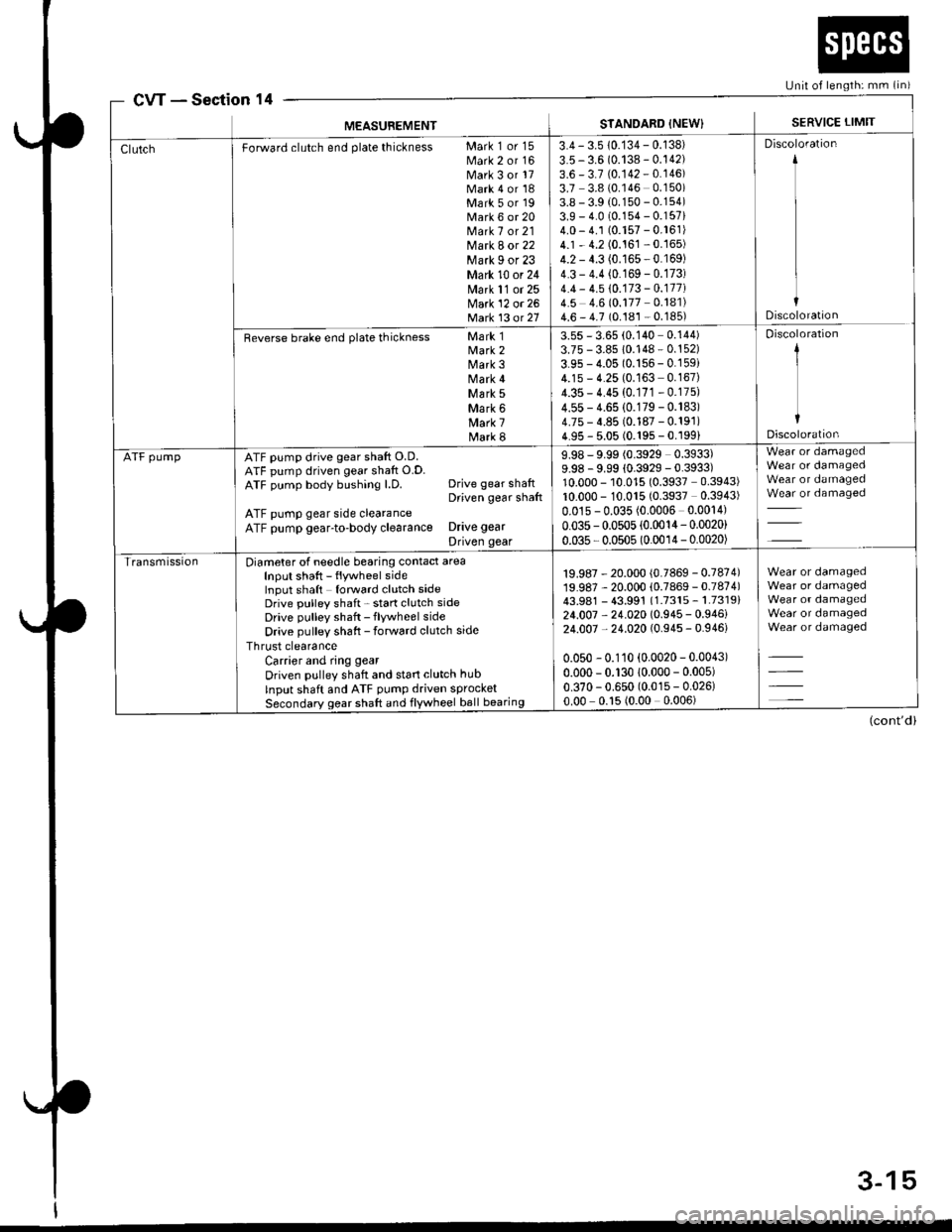
cwSection 14[Jnit of length: mm (in)
MEASUBEMENTSTANDARD {NEW}SERVICE LIMIT
Forward clutch end plate thickness Mark 1 or 15Mark 2 or 16Mark 3 or 17Mark 4 or 18Mark 5 or 19Mark 6 or 20Mark 7 or 21Mark 8 or 22Mark I or 23Mark 10 or 24Mark 11 or 25Mark 12 or 26Matk 13 ot 21
3.4 - 3.5 10.134 - 0.138)
3.5 - 3.6 (0.138 - 0.142)3.6 - 3.7 (0.142 - 0.146)3.7 3.8 (0.146 0.150)3.8 - 3.9 (0.150 - 0.154)3.9 - 4.0 (0.154 - 0.157i4.0 - 4.1 (0.157 - 0.161)4.1 - 4.2 (0.161 - 0.165)4.2 - 4.3 (0.165 - 0.169)4.3 - 4.4 (0.169 - 0.173)4.4 - 4.5 10.173 - 0.177i4.5 4.6 (0.177 0.181)4.6 - 4.7 (0.181 - 0.185)
Discoloration
Discoloration
Reverse brake end plate thickness Mark 1Mark 2Mark 3Mark 4\44 rk 5Mark 6Mark 7Mark 8
3.55 - 3.65 (0.140 0.144)3.75 - 3.85 10.148 - 0.152)
3.95 - 4.05 (0.156 - 0.159i4.15 - 4.25 (0.163 0.167)4.35 - 4.45 (0.171 - 0.175)
4.55 - 4.65 (0.179 - 0.183)4.75 - 4.85 (0.187 - 0.191)4.95 - 5.05 (0.195 - 0.199)
Discoloration
1
IDiscoloration
ATF pumpATF pump drive gear shaft O.D.ATF pump driven gear shaft O.D.ATF pump body bushing l.D. Drive gear shaftDriven gear shaft
ATF pump gear side clearanceATF pump gear-to-body clearance Drive gear
Driven gear
9.98 - 9.99 (0.3929 0.3933)9.98 - 9.99 {0.3929 - 0.3933)10.000 - 10.015 (0.3937 0.3943)10.000 - 10.015 (0.3937 0.3943)
0.01s - 0.035 (0.0006 0.0014)
0.035 - 0.0505 (0.0014- 0.0020)
0.035 - 0.0505 (0.0014 - 0.0020)
Wear or damagedWear or damagedWear or damagedWear or damaged
TransmissionDiameter of needle bearing contact areaInput shaft - flywheel sideInput shaft forward clutch sideDrive pulley shaft - start clutch sideDrive pulley shaft - flywheel side
Drive pulley shaft - forward clutch side
Thrust clearanceCarrier and ring gear
Driven pulley shaft and start clutch hub
Input shaft and ATF pump driven sprocketSecondary gear shaft and flywheel ball bearing
19.987 - 20.000 (0.7869 - 0.7874)19.987 - 20.000 (0.7869 - 0.7874)43.981 - 43.991 (1.7315 - 1.7319)24.007 - 24.020 (0.945 - 0.946)24.007 - 24.020 (0.945 - 0.946)
0.050 - 0.110 (0.0020 - 0.0043)
0.000 - 0.130 10.000 - 0.005)
0.370 - 0.650 (0.015 - 0.026)0.00 0.15 (0.00 0.006)
Wear or damagedWear or damagedWear or damagedWear or damagedWear or damaged
(cont'd)
3-15
Page 61 of 2189

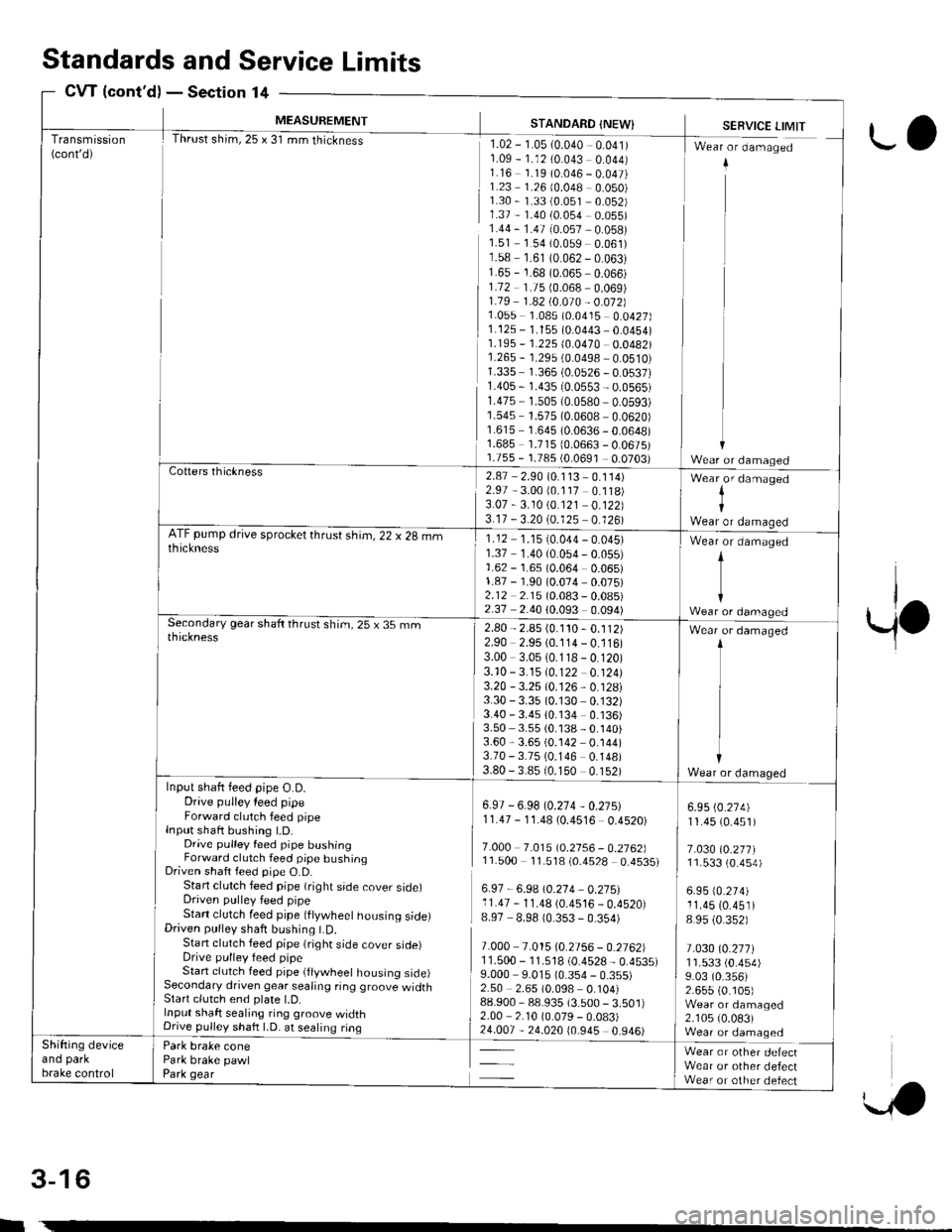
Transmission(cont'd)
MEASUREMENT
Thrust shim,25 x 31 mm thickness
STANDARD {NEW}
rlz-r-osr-o.o+o oolrr1.09 - 1.12 (0.043 0.044)1.16 1.19 (0.046 - 0.047)1.23 1.26 (0.048 0.050)1.30 - 1.33 (0.051 0.052)1.37 - 1.40 (0.054 0.055)1.44 - 1.47 (0.057 0.058)1.51 1.54 (0.059 0.061)1.58 1.61 (0.062 - 0.063)1.65 - 1.68 (0.065 0.066)1.72 1.75 {0.068 0.069)1.79 1 .a2 t0.O10 - 0.012]}1.055 1.085 (0.0415 0.0427)1.125 - 1.155 (0.0443 0.0454)1.195 - '�I.225 (0.0470 0.0482)1.265 - 1.29s (0.0498 0.0510)1.335 1.365 (0.0526 - 0.0537)1.40s - 1.435 (0.0553 - 0.0565)r.475 1.505 {0.0580 0.0593)1.545 1.575 (0.0608 0.0620)1.615 1.645 (0.0636 - 0.0648)1.685 1.71510.0663 - 0.0675)1.755 - 1.785 {0.0691 0.0703)
SERVICE LIMIT
I Wr"r - d-"-"g"d
ii
11
ir
Cotters thickness2.87 - 2.90 (0.1 13 - 0.114)2.97 - 3.00 (0.117 0.118)3.07 -3.10 \0.121 0.122)3.17 - 3.20 (0.125 0.126)
Wear,or damaged
IWear or damaoedATF pump drive sprocket thrust shim, 22 x 28 mmthickness1.12 1.1510.044 - 0.045)1.37 1.40 (0.054 - 0.055)1.62 - 1.65 (0.064 0.065)1.87 - 1.90 (0.074,0.075)2.12 2.15 (0.083 - 0.08s)2.37 2.40 (0.093 0.094)
Wear or damaged
t
{Wear or damagedSecondary gear shaft thrust shim, 25 x 35 rnmthickness2.80 - 2.85 (0.1'�t0 - 0.112)2.90 2.95 (0.114 - 0.116)3.00 3.05 (0.118 - 0.120)3.10 -3.15 10.122 0.124)3.20 - 3.25 (0.126, 0.128i3.30 - 3.35 (0.130 0.132)3.40 - 3.4s 10.134 0.136)3.50 3.55 (0.138 - 0.140)3.60,3.65 (0.142 0.144)3.70 - 3.75 (0.146 0.148)3.80 - 3.8510.150 0.152)
Wear or damaged
Wear or damaqedInput shaft feed pipe O.D.Drive pulley leed pipeForward clutch feed pipeInput shaft bushing t.D.Drive pulley feed pipe bushingForward clutch feed pipe bushingDriven shaft feed pipe O.D.Start clutch feed pipe (right side cover side)Driven pulley feed pipeStan clutch feed pipe (ftywheet housing side)Driven pulley shaft bushing LD.Stan clutch feed pipe (right side cover sroerDrive pulley feed pipeStart clutch feed pipe (flywheel housing side)Secondary driven gear sealing ring groove widthStart clutch end plate l.D.Input shaft sealing ring groove widthDnve pullev shaft LD. at sealing ring
Park brake conePark brake pawlPark gear
6.97 - 6.98 (0.274 - 0.27s)11.47 - 1'1.48 (0.4516 0.4520)
7.O0O 7.0t510.2156 - 0.2762]l11.500 11.518 (0.4528 0.4535)
6.97 - 6.9A \0.214 0.275:l11.47 - 11.48 (0.4516 _ 0.4520)8.97 8.98 10.353 - 0.354)
7.000 7.015 (0.2756 - 0.2762)1 1.500 - '11.518 (0.4528 - 0.4535)9.000 9.015 10.354 - 0.355)2.50 2.65 (0.098 0.104)88.900,88.935 (3.500 - 3.501)2.00 2.10 10.079 - 0.083)
5*
6.95 (0.274)
11.45 (0.451)
7.030 (0.277)11.533 (0.4s4)
6.95 (0.274)
11.45 (0.451)
8 95 (0.352)
t.030l0.2t7l1r.533 (0.454)
9.03 (0.356)2.655 (0. r05)Wear or damaged2.105 (0.083)Wear or damaqedShifting deviceano parKbrake control
Wear or other defectWear or other defectWear or other defect
Standardsand Service Limits
CW {cont'd)Section 14
rl
w
3-16
ro
Page 373 of 2189

PGM-FI System
System Description
CKP/TDC/CYP Sensor
MAP Sensor
IAT SensorTP SensorEGR Valve Lift Sensor*'Primary H02SSecondary HO2SVSSBARO SensorELD*'KS€Starter SignalALT FR SignalAir Conditioning SignalA/T Gear Position SignalBattery Voltage {lGN.1}Erake Switch SignalPSP Switch SignalFuel Tank Pressure Sensor*iVTEC Pressure Switch*5Clutch Switch Signal*6Countershaft Speed SensornBMainshaft Speed Sensorrs
-\
----t /
F;ilrr j"-----fi-tri-'r.;l
Fb"t."'i" d" c;;il
F,h"'c;;tr*".io";-l
@."r.l"sc;;ll
EaM/PcM B""k-p F"""till
r\
-:/
Fuel IniectorsPGM-Fl Main Belay {Fuel Pump)MILIAC Valve!y'C Compressor Clutch RelayRadiator Fan Relay*,Condenser Fan RelayALT*'lcMEVAP Purge Control Solenoid
Primary HO2S HeaterSecondary H02S HeaterEGR Control Solenoid Valve*rEGR valve*6EVAP Bypass Solenoid Valve*'EVAP Control Canister Vent Shut
VTEC Solenoid Valve*5DLCLock-up Control Solenoid Valve*aShift Control Solenoid Valve*3Linear Solenoid Valve*3
*1: Dl6Y5 engine*2: USA model*3: CW (D16Y5 ensine), D16Y8 engine and 81642 ensine*4: '96 D16Y8 engine lcoupe),'97 Dl6Y7 engine (coupe: KL model, sedan: KL (LX) model),'97 D16Y8 engine {coupe: all models, sedan: KLmodel),'98-all models,'99'all models,'00-all models+5: D16Y5, D16Y8,816A2 engine*6: M/T (D16Y5 enginei*7: CVT 1D'l6Y5 engine)+8: A/T (D16Y7, D16Y8 engine)*9: '96 D16Y5 engine,'96 D16Y7 engine,'96 Dl6Y8 engine (sedan),'97 D16Y5 engine,'97 Dl6Y7 engine (coupe: KA, KC models, sedan:KA, KC, KL (LX) models, hatchback: all models),'97 D16Y8 engine (sedan: KA, KC modelsi
PGM-FI Sy3lem
The PGM-Fl system on this model is a sequential multipon fuel injection system.
Fuel iniector Timing and Duration
The ECM/PCM contains memories for the basic discharge durations at various engine speeds and manifold air flow rates.
The basic discharge duration, after being read out from the memory. is further modified by signals sent from various sen-
sors to obtain the final discharge duration.
ldle Air Control
ldle Air Control Valve llAC Valve)
When the engine is cold. the A,/C compressor is on, the transmission is in gear, the brake pedal is depressed, the P/S load
is high, or the alternator is charging, the ECM/PCM controls current to the IAC Valve to maintain the correct idle speed.
lgnition Timing Control
. The ECM/PCM contains memories for basic ignition timing at various engine speeds and manifold air flow rates.
lgnition timing is also adjusted for engine coolant temperature.
. Aknockcontrol system was adopted which sets the ideal ignition timing for the octane rating ofthegasoline used.*3
Othgr Control Funqtions
1. Starting Control
When the engine is started, the ECM/PCM provides a rich mixture by increasing fuel injector duration.
2. Fuel Pump Control
. When the ignition switch is initially turned on, the ECM/PCM supplies ground to the PGM-Fl main relay that sup-plies current to the fuel pump for two seconds to pressurize the fuel system.. When the engine is running, the ECI\4PCM supplies ground to the PGM-FI majn relay that supplies current to the fuel
oumo.
. When the engine is not running and the ignition is on, the ECM/PCM cuts ground to the PGM-FI main relay which
cuts current to the fuel pump.
11-104
INPUTS
ENGINE CONTROL MODULE (ECMY
POWERTRAIN CONTROL MODULE (PCM) OUTPUTS
Page 469 of 2189

ldle Gontrol System
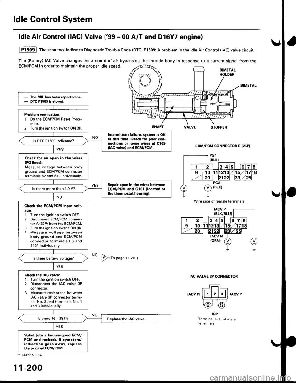
The (Rotary) IAC Valve changes the amount of air bypassing the throttle body in response to a current signal from the
ECM/PCM in order to maintain the proper idle speed.BIMETALHOLDER
BIMETAL
SHAFTVALVESTOPPER
ECM/PCM CONNECTOR B {25P}
(To page 11-201)
IAC VALVE 3P CONNECTOR
IACV NIACV P
ldle Air Control {lACl Valve ('99 - 00 A/T and Dl6Y7 enginel
YES
1P1509 lThescantool indicates Diagnostic Trouble Code (DTC) P1509:A problem inthe idleAirControl (lAC)valve circuit.
IGP
Terminal side of maleterminals
Sub3titute e known-good ECM/PCM .nd recheck. lf 3vmptom/indicalion goos away, replac6thc original ECM/PCM.
*: IACV N line
11-200
Tho MIL has b€en reported on.OTC P1509 is sto.ed.
Problem verilicationr1. Do the ECM/PCM Reset Proce-dure.2. Turn the ignition switch ON (ll).
Intermittont tailure, sy3tem i3 OKat thb time. Check for poor con'noctions or loose wiros at C109(lAC velvel and ECM/PCM.
ls DTC P1509 indicated?
Check for an oDen in the wilosIPG linesl:Measure voltage between bodyground and ECM/PCM connectorterminals 82 and 810 individually.
Ropail open in the wires be'tw€enECM/PCM .nd G101 llocated .tthe the.mostat housingl.ls there more than 1.0 V?
Check tho ECM/PCM input volt-age:1. Turn the ignition switch OFF.2. Disconnect ECM/PCM connec-tor A (32P)trom the ECM/PCM.3. Turn the ignition switch ON (ll).
4, Measure voltage betweenbody ground and ECM/PCMconnector terminals 86 and815* individually.
Chock the IAC v.lve:1. Turn the ignition sw;tch OFF.2. Disconnect the IAC valve 3Pconnoctor.3. Measure resistance betweenIAC valve 3P connector termi'nal No. 2 and terminals No. 1and 3 individually.
ls there 16 - 28 O?
Wire side of female terminals
Page 681 of 2189

Description
The automatic transmission is a 3-element torque converter and a dual-shaft electronically controlled unit which provides
4 soeeds forward and 1 reverse.
Torque Convertel, Geats, and Clutches
The torque converter consists of a pump, turbine and stator, assembled in a single unit. They are connected to the engine
crankshaft so they turn together as a unit as the engine turns. Around the outside of the torque converter is a ring gear
which meshes with the starter pinion when the engine is being started. The entire torque converter assembly seryes as a
flywheel while transmiuing power to the transmission mainshaft.
The transmission has two parallel shafts: the mainshaft and the countershaft. The mainshaft is in Iine with the engine
crankshaft. The mainshaft includes the 1st, 2nd and 4th clutches, gears tor 2nd, 4th, reverse and lst (3rd gear is integral
with the mainshaft, while the reverse gear is integral with the 4th gear). The countershaft includes the 3rd clutch, and
gears for 3rd,2nd, 4th, reverse. 1st and park. The gears on the mainshaft are in constant mesh with those on the counter-
shaft. When certain combinations of gears in transmission are engaged by clutches. power is transmitted from the main-
shaft to the countershaft to provide E, ld, E, and E positions.
Electronic Control
The electronic control svstem consists of the Powertrain Control Module {PCM), sensors, a linear solenoid and four
solenojd valves. Shifting and lock-up are electronically controlled for comtonable driving under all conditions. The PCM is
located below the dashboard, under the front lower panel on the passenger's side
Hydraulic Control
The valve bodies include the main vatve body, the secondary valve body, the regulator valve body, the servo body and the
lock-up valve body through the respective separator plates, They are bolted on the torque converter housang
The main valve body contains the manual valve, the 1-2 shift valve. the 2nd orifice control valve, the CPB {Clutch Pressure
Back-up) valve, the modulator valve. the servo control valve, the relief valve, and ATF pump gears The secondary valve
body contains the 2-3 shift valve. the 3-4 shift valve, the 3-4 orifice control valve, the 4th exhaust valve and the CPC (Clutch
pressure Control) valve. The regulator valve body contains the pressure regulator valve, the torque converter check valve,
the cooler relief valve, and the lock-up control valve. The servo body contains the servo valve which is integrated with the
reverse shift fork, and the accumulators. The lock-up valve body contains the lock-up shift valve and the lock-up timing
valve. The linear solenoid and the shift control solenoid valve Ay'B are bolted on the outside of the transmission housing,
and the lock-up control solenoid valve Ay'B is bolted on the outside of the torque converter housing. Fluid from regulator
passes through the manual valve to the various control valves. The clutches receive fluid from their respective teed pipes
or internal hydraulic circuit.
Shift Control Mechanism
Input from various sensors located throughout the car determines which shift control solenoid valve the PCM will activate
Activating a shift control solenoid valve changes modulator pressure, causing a shift valve to move. This pressurizes a line
to one of the clutches, engaging that clutch and its corresponding gear, The shift control solenoid valves A and B are con-
trolled by the PCM.
Lock-up Mechanism
In ,Dt1 position, in 3rd and 4th. and in E position in 3rd, pressurized fluid is drained from the back of the torque converter
through a fluid passage, causing the lock-up piston to be held against the torque converter cover. As this takes place, the
mainshaft rotates at the same as the engine crankshaft. Together with hydraulic control, the PCM optimizes the timing of
the lock-up mechanism. The lock-up valves control the range of lock-up according to lock-up control solenoid valves A and
B, and linear solenoid. When lock-up control solenoid valves A and B activate, the modulator pressure changes The lock-
up control solenoid valves A and B and the linear solenoid are controlled by the PCM.
(cont'd)
14-3
Page 721 of 2189

I
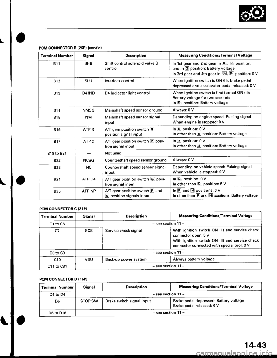
PCM CONNECTOR B {25P1 {cont'dl
Terminal NumberSignalDescriptionMeasuring Conditions/Terminal Vohage
811SHBShift control solenoid valve B
control
In 1st gear and 2nd gear in -q1, q11 position,
and in E] position: Battery voltage
In 3rd gear and 4th gear in lD.J, [Dr- position: 0 V
B't2SLUInterlock controlWhen ignition switch is ON (ll), brake pedal
deoressed and accelerator Dedal released: 0 V
813D4 INDD4 Indicator light controlWhen ignition switch is first turned ON (ll):
Battery voltage for two seconds
In E position: Baftery voltage
B't 4NMSGMainshaft speed sensor groundAlways: 0 V
E tcNMMainshaft speed sensor signal
input
Depending on engine speed: Pulsing signal
When engine is stopped: 0 V
816ATP RAy'T gear position switch Eposition signal input
InE position: 0V
In other than E position: Battery voltage
817ATP 2A/T gear position switch E posi-
tion signal input
InE position: 0V
In orher than E position: Battery voltage
818 to 821Not used
s22NCSGCountershatt speed sensor groundAlwaysr 0 V
B�23NCCountershaft speed sensor signal
input
Depending on vehicle speed: Pulsing signal
When vehicle is stopped: 0 V
B�24ATP D4Ay'T gear position switch lor posi-
tion signal input
InEposition:0V
In other than 6 position: 5 V
ATP NPA,/T gear position switch E and
N position signals input
InE and E positions: 0V
In otherthan E and N] positions: Battery voltage
PCM CONNECTOR C {31P)
Terminal NumberSignalDescriptionMeasuring Conditions/Terminal Voltage
Cl to C6- see section 11 -
c1Service check signalWith ignition switch ON (ll) and service check
connector oDen; 5 V
With ignition switch ON (ll) and service check
connector connected with sDecial tool: 0 V
C8 to Cg- see section 11 -
c10VBUBack-up power systemAlways battery voltage
C11 to C31- see section '11 -
PCM CONNECTOR D (16P}
Terminal NumberSignalDescriptionMeasuring Conditions/Terminal Voltage
Dl to D4- see section 11 -
D5STOP SWBrake switch signal inputBrake pedal depressed: Battery voltage
Brake pedal released: 0 V
D6 to D16- see section 1 l -
14-43
Page 725 of 2189

FCM CONNECTOR D {16P)
\o
14-47
Terminal NumberSignalDo3criptionMeasuring Conditions/Torminal Vohage
D1LCALock-up control solenoid valve A
control
When lock-up is ON: Battery voltage
With no lock-up: 0 V
SHBShift control solenoid valve B
control
In E position, in 1st and 2nd gear in E, E
position: Battery voltage
ln 3rd gear in E, E, in 4th gear in E posi-
tion;0 V
D3LCBLock-up control solenoid valve B
control
When full lock-up: Battery voltage
With half lock-up: Pulsing signal
D4Not used
D5VB SOLLock-up control solenoids, shift
control solenoids and linear
solenoid power supply electrode
with ignition switch oN (ll): Battery voltage
With ignition switch OFF: 0 V
D6ATP RAy'T gear position switch
E position input
tnEposition:0V
In other than E position: Approx. 10 V
SHAShift control solenoid valve A
control
In E] position, in 2nd and 3rd gear in p!, [Q]
position: Battery voltage
In 1st gear in E, @ position, in 4th gear in El
Dosition: 0 V
D8ATP D3A/T gear position switch
E position input
In E position:0V
In otherthan @ position: Approx. 10 V
D9ATP D4Ay'T gear position switch
E position switch
In El position: 0 V
In other than E position: Approx. 5 V
D10NCCountershaft speed sensor signal
input
Depending on vehicle speed: Pulsing signal
When vehicle is stooped: 0 V
D11NMMainshaft speed sensor signal
Inpur
Depending on engine speed: Pulsing signal
When engine is stopped: 0 V
D't2NMSGMainshaft speed sensor ground
D13ATP NPAy'T gear position switch E and
E position input
InE and E positions: 0V
In other than E and E positions: Approx. 10 V
D14AfP 2Ay'T gear position switch
E position input
tnEposition;0V
In other than E position: Approx. 10 V
D16NCSGCountershaft speed sensor
ground
Page 871 of 2189

Continuously Variable Transmission (CVTI
Special Tools ................ 14-194
Description .................... 14-195
Clutches/Reverse Brake/Planetary
Gear/Pulleys .......... 14-198
power Flow ..............,..... 14-200
Electronic Control SYstem(,96 - 98 Modets) ......14-203
Electronic Control System
('99 - oo Models) " 14-205
Hydraulic Control '....... 14-208
Hydraulic Flow .'..-.....'... '14-212
Park Mechanism .....-...'.' 14-222
Eleqtrical Systom
Component Locations'96 - 98 Models """"""' 14-224,99 - 00 Modets ............. 14-225
TCM Circuit Diagram ('96 - 98 Models) ............. 14-226
TCM Terminal Voltage/Measuring Condiiions ('96 - 98 Models) '.... 14-228
PcM Circuit Oiaqram{A/T Control System: '99 - 00 Models} ...--.... 14-230
PCM Terminal Voltage/Measuring Conditions('99 - 00 Models)
A/4 Control System .'.'...14-232
Troubleshooting Procedures ... . .... .....',........."' '14-234
Symptom-to-ComPonent Chart
Electrical System - '96 - 98 Models ......'..... '14-234
Electrical System -'99 - 00 Models ..'....-..-. '11-210
Electrical Troubleshooting
Troubleshooting Flowcharts('96 - 98 Models) """'11-242
Troubleshooting Flowchart
('99 - 0O Modets) ...... 14-265
Linear Solenoids/lnhibitor Solenoid
Test ......................... . ...... 14-29f
Drive Pulley/Driven Pulley/Secondary Gear
Shaft Speed Sensors
Replacement .........'...... .14-292
Start Clutch Control
Start Clutch Calibration Procedure ....... ....,. 14-293
Hydraulic SYstem
Symptom-to-ComPonent Chart
Hydraulic System '.'.......14-294
Road Test ............................ 14-296
Stall Speed
Test......................... ...... 14-294
Fluid Level
Checking/Changing ....... 14-299
Pressure Testing ................. 14-300
Lower Valve BodY AssemblY
Replacement ..........,... 14-302
ATF Filter
Removal/lnstallation ..... 14-303
Transmission
Transmission
Removal ........... . 14-304
lllustrated Index
Transmission/Lower Valve BodY
Assembly ................. 14-308
Transmission Housing/Flywheel Housing ... 14-310
End Cover/f ntermediate Housing ..........'.'.... 14-312
Transmission Housing/Lower Valve Body Assembly
Removal ..........'.... .. " 14-314
Transmission Housing/Flywhesl Housing
Removal ................. ........ 1+316
End Cover/lntermediate Housing
14-318Removal .........,...............
Manual Valve Body
Disassembly/lnspection/Reassemblv .'.'.'..... 1 4-320
Forward Clutch
lltustrated Index ........................................ 14-321
Disassemblv .................. 14-322
Reassemblv , ,, . ',','......14-324
Secondary Gear Shaft
25 x 35 mm Thrust Shim Selection ..'.'....-... 14-324
Differential
lllustrated lndex ...,.....................,.,...-.-.-...'... 14-329
Backlash Inspection .-....14-329
Bearing Replacement ......'........'....'... ....'... 14-330
Differential Carrier Replacement ........'........ 14-330
Oil Seal Removal ........... 14-331
Oil Seal Installation/Side Clearance ....... . . 14-331
Flywheel Housing Input Shaft Oil Seal
Replacement .....,.... ...'.'.. 14-333
Transmission Housing Bearings
Driven Pulley Shaft Bearing
Replacenient ...................'. . ...................'.. 14-334
Secondary Gear Shaft Bearing
Reolacbment ...................... . .......... . ........ 14-335
Flywheel Housing Beating
Secondary Gear Shaft BearingReo1acement..................,........................... 14-335
Ring Gear Bearing
Replacement......... ........ 14-336
Control Shaft Assembly
Removal/lnstallation ....................'........... 14-336
Transmission
Reassembly .................. 14-338
Flywheel/Drive Plate .. . ...... . ...... ... . ....-.....'.'...14-341
Transmission
lnstalation ..................... 14-348
Cooler Flushing .'......... 14-352
shift cable
Removal/lnstallation....'........." """ 14-354
Adjustment .......'........ 14-355
Shift Lever ........................,. 14'356
Shift Indicator Panel
Adjustment ................ 14-357
ATF Cooler/Hoses
lnsta llation ......,,...... .... 14-357