Page 1014 of 2189
Transmission
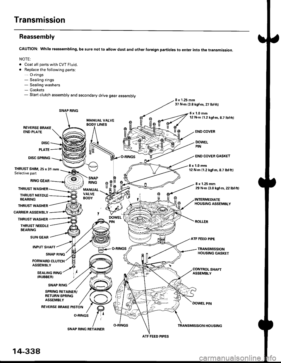
Reassembly
CAUTION: While reassembling. be sure not to sllow dust and othor foreign particles to enter into the transmission.
NOTE:
. Coat all parts with CVT Fluid.
. Replace the following parts:- O-rings- Sealing rings- Sealing washers- Gaskets- Start clutch assembly and secondary drive gear assembly8 x 1.25 mm37 N.m {3.8 kgf.m,27 lbtftl
MANUAL VALVE
6x1.0mm12 N m 11.2 kgf.m,8.7 lbl.ft)
LINESREVERSE BRAKEEND PLATE
Dtsc
PLATE
DISC SPRING
THRUST WASHER
CARRIER ASSEMBLY
THRUST WASHER
THRUST NEEDLEBEARING
END COVEB
DOWELPIN
END COVER GASKET
6x1.0mm12 N.m 11.2 kgtm,8.7 lbtft)THRUST SHIM,25 x 31 mmSelective part
RING GEAR
THRUST WASHER
THRUSTBEARING
8 x 1.25 mm29 N.m 13.0 kgl m, 22 lbtftl
INTERMEDIATEHOUSING ASSEMBLY
ROLI.IR
SNAPRINGeBH^cMANUALVALVEBOOY
SUN GEAR
INPUT SHAFT
(RUBEERI
ATF FEED PIPE
O-RINGSTRANSMISSIONHOUSING GASKETSNAP RING
FORWARD CLUTCH
SNAP RING
SHAFTASSEMALY
DOWEL PtN
SPRING RETAINER/RETURN SPRINGASSEMBLY
REVERSE BRAKE PISTON
O.RINGS
SNAP RING
ATF FEED PIPES
14-338
SNAP RING RETAINERTRANSMISSION HOUSING
Page 1016 of 2189
Transmission
16.
Reassembly (cont'dl
21.
17.
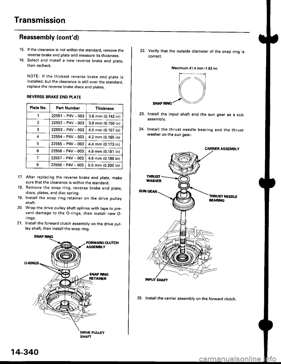
lf the clearance is not within the standard, remove thereverse brake end plate and measure its thickness.Select and install a new reverse brake end Dlate.then recheck.
NOTE: lf the thickest reverse brake end olate isinstalled, but the clearance is still over the standard,replace the reverse brake discs and plates.
REVERSE BRAKE END PLATE
After replacing the reverse brake end plate, makesure that the clearance is within the standard.Remove the snap ring, reverse brake end plate,
discs, plates. and disc spring.
Install the snap ring retainer on the drive pulley
shaft.
Wrap the drive pulley shaft splines with tape to pre-
vent damage to the O-rings, then install new O-n ngs.
Install the forward clutch assembly on the drive pul-
ley shaft, then installthe snap ring.
SITAP
O-RINGS
18.
19.
20.
SI{AP RIM;BETA EB
DRIVE PUI.IEYSHAFT
Plat6 No.Part NumberThickness
122551 - P4V - 0033.6 mm (0.142 in)
22552-P4V-0033.8 mm (0.150 in)
22553-P4V-0034.0 mm (0.157 in)
422554-P4V-0034.2 mm (0.165 in)
522555-P4V-0034.4 mm (0.173 in)
622556-P4V-0034.6 mm (0.181 in)
722557 -P4V -OO34.8 mm (0.189 in)
822558-P4V-0035.0 mm (0.200 in)
14-340
25. Installthe carrier assembly on the forward clutch.
22. Verity that the outside diameter ol the snap ring iscorrect.
SI{AP RIiIG
Install the input shaft and the sun gear as a subassemDry.
Install the th.ust needle bearing and the thrustwasher on the sun gear.
CARRIER ASSEMBLY
THFUST I'IEEDI!EEARIT{G
Msximum 41.4 mm 11.63 in)
IHruST
Page 1019 of 2189
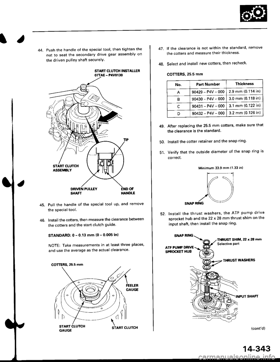
44. Push the handle of the special tool, then tighten the
nut to seal the secondary drive gear assembly on
the driven pulleY shaft securelY.
STAAT CLUTCH Ii'ISTALIIR07TAE - PaV0130
OF
46.
SHAFTHA'{DI,-E
Pull the handle of the special tool up, and remove
the special tool.
lnstallthe cotters, then measure the clearance Delween
the cotters and the start clutch guide
STANDARD: 0 - 0.13 mm (0 - 0.005 inl
NOTE: Take measurements in at least three places,
and use the average as the actual clearance
GAUGE
lil(il
COTTERS, 25.5 mm
START 1
GAUGCSTART CLUTCH
14-343
47.
48.
lf the clearance is not within the standard, remove
the cotters and measure their thickness
Select and install new cotters, then recheck.
COTTERS, 25.5 mm
After replacing the 25.5 mm cotters, make sure that
the clearance is the standard
lnstall the cotter retainer and the snap rlng
Verify that the outside diameter of the snap ring is
correct.
Minimum 33.9 mm (1.33 in)
SNAP RII{G
lnstall the thrust washers. the ATF pump drrve
sprocket hub and the 22 x 28 mm thrust shim on the
inDUt shaft, then install the snap ring.
49.
50.
52.
THRUST WASXERS
INPUT SHAFT
(cont'd)
No.Part NumberThickness
90429-P4V-0002.9mm(0.114 in)
B90430-P4V-0003.0mm(0.118 in)
c90431 -P4V-0003.1 mm (0.122 ln)
D90432-P4V-0003.2 mm (0.126 in)
SNAPRING\
ATF PUMP DRIVESPROCKET HUB
THFUST SHIM, 22 x 2a mm
Selective pan
Page 1024 of 2189
Transmission
Installation
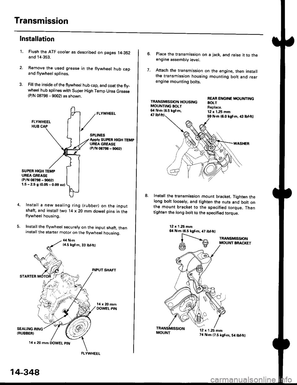
Flush the ATF cooler as described on pages 14-352and 14-353.
Remove the used grease in the flywheel hub caDand flywheel splines.
Fill the inside of the flywheel hub cap, and coat the fly-wheel hub splines with Super High Temp Urea Grease(P/N 08798 - 9002) as shown.
L
SEALING RING{RUEBER)
SPLINESApply SUPEB HlcH TEMPUREA GREASElPlN 08798 - 90O2t
SUPER HIGH TEMPUREA GREASE(P/N 08798 - !)00211.5-2.5 g 10.05-0.t9 oz)
Install a new sealing ring (rubber) on the inoutshaft, and install two '14 x 20 mm dowel Dins in theflywheel housing.
Install the flywheel securely on the input shaft, theninstallthe starter motor on the flywheel housing.
4,1Nmla.5 kgt.m, 33 tbt.ft)
INPUT SHAFT
STARTER
l4 x 20 mm DOWEL ptN
.4;i "lrj
,i rr,"r., ., a
14-348
FLYWHEEL
MOUI{T74 N.m (7.5 tstm,5a tbtftt
6. Place the transmission on s jack, and raise it to theengine assembly level.
7. Anach the transmission on the engine, then installthe transmission housing mounting bolt and rearengine mounting bolts.
TRANSMISSION HOUSINGMOUNTING BOIT6,1 N.m 16.5 kgl.m,47 tbtttl59 Nrn {6.0 kgl.m. ,€ lbt ftl
WASHER
lnstall the transmission mount bracket. Tighten thelong bolt loosely, and tighten the nuts and bott onthe mount bracket to the specified torque. Thentighten the long bolt to the specified torque.
REAR ENGINE MOUNTINGBOLTReplace.12 x 1.25 mm
12x 1.25 mn6,r N'm 16.5 kgtm,47 tbtftl
l-".--..-,^
G\V
TRANSMISSONMOUNT BRACKET
12 x 1.25 mn
Page 1076 of 2189
System Description
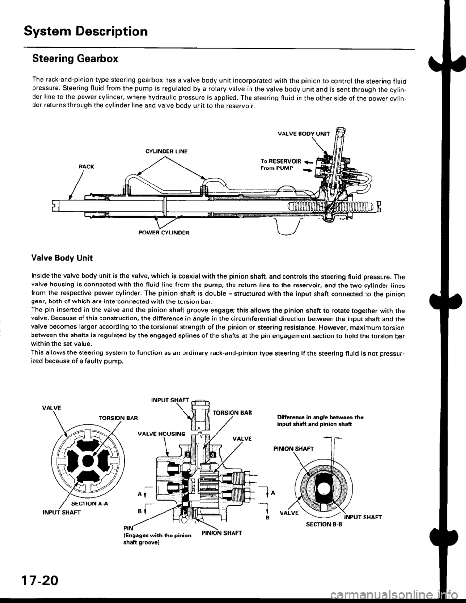
Steering Gearbox
The rack-and-pinion type steering gearbox has a valve body unit incorporated with the pinion to control the steering fluidpressure. Steering fluid from the pump is regulated by a rotary valve in the valve body unit and is sent through the cylin,der line to the power cylinder, where hydraulic pressure is applied. The steering fluid in the other side of the power cylin,der returns through the cylinder line and valve body unit to the reservoii.
VALVE EODY UNIT
CYLINDER LINE
To RESERVOm +-From PUMP -;
POWER CYLINDER
Valve Body Unit
Inside the valve body unit is the valve, which is coaxial with the pinion shaft, and controls the steering fluid pressure. Thevalve housing is connected with the fluid line from the pump, the return line to the reservoir, and the two cylinder linesfrom the respective power cylinder. The pinion shaft is double - structured with the input shaft connected to the piniongear, both of which are interconnected with the torsion bar.
The pin inserted in the valve and the pinion shaft groove engage; this allows the pinion shaft to rotate together with thevalve. Because of this construction, the difference in angle in the circumferential direction between the input shaft and thevalve becomes larger according to the torsional strength of the pinion or steering resistance. However, maximum torsionbetween the shafts is regulated by the engaged splines of the shafts at the pin engagement section to hold the torsion barwithin the set value,
This allows the steering system to function as an ordinary rack-and-pinion type steering if the steering fluid is not pressur-
ized because of a faulty pump,
VALVE
Difforence in angle botwoon theinput shaft and pinion shsft
PINION SHAFT
lo
INPUT SHAFT
-l
a
17-20
INPUT SHAFT
Page 1077 of 2189
Pressure Control
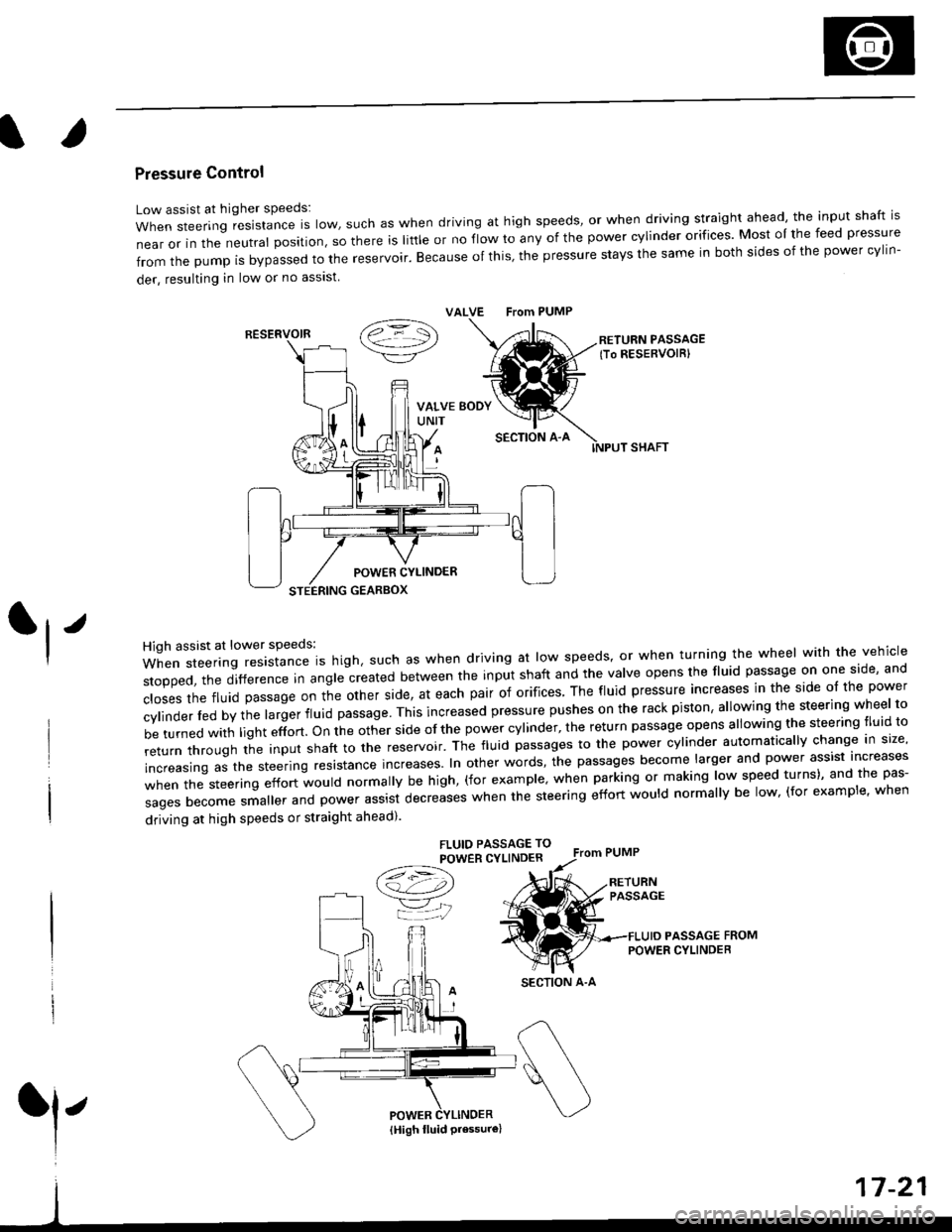
Low assist at higher speeds:
WhensteeringresistanceIsIow,suchaswhendrivingathighspeeds,orwhendrivingstraightahead,theinputshaftis
near or in the neutral position, so there is little or no fiow ro any of the power cylinder orifices. Most oI the feed pressure
fromthepumpisbypassedtothereservoir.Becauseofthis,thepressurestaysthesameinbothsidesofthepowercy||n-
der, resulting in low or no asslst
VALVE From PUMP
SECTION A-A
RETURN PASSAGElTo RESERVOIRI
POWER CYLINDER
STEERING GEARBOX
High assist at lower speeds:
When steering resistance is high. such as when driving at low speeds' or when turning the wheel wirh the vehicle
stopped,thedifference|nang|ecreatedbetweentheinputshaftandtheVa|veopensthef|uidpassageononeside,and
c|osesthefluidpassageontheotherside,ateachpairoforifices'Thef|uidpressureincreasesinthesideo|thepower
cy|inder|edbythe|argerf|uidpassage'Thisincreasedpressurepushesontherackpiston,a|lowingthesteeringwhee|to
be turned with light effort. on the other side of the power cylinder, the return passage opens allowing the steering tluid to
returnthroUghtheinputshafttothereservoir'Thef|uidpassagestothepowercy|inderautomatica||ychangeins|ze,
increasing as the steering resrstance increases. In other words, the passages become larger and power assist increases
when the steering effort would normally be high, (for example' when parking or making low speed turns)' and the pas-
sagesbecomesma||erandpowerassistdecreaseswhenthesteeringeffortwou|dnorma||ybe|ow,(forexamp|e,when
driving at high speeds or straight ahead).
FLUIO PASSAGE TO
POWER CYLINDER
/t=\\a!-4,))
=YjJ
RESERVOIR
SECTION A-A
l'
{High fluid Pressure}
Page 1924 of 2189
@@
i t FusE 13
LJ::-i1":--.i
---1 UNDET
| | ryql* !5ts?'n| ) iL"' li'r:,o,
rT ILJ---------J
--1 UNDER.DASH T ---1 UNDER-HOOD
i l$5ffif{61 !F'[]:':'* itte*- l"l;?::*'
L-g----- ---Y---J3 r-----
---------;r
".* I veuar-r< |, t_____ _1ft9#;,,
"* | ;-{ 8pfitli*| ".'"'* |
n"""
l----l .rr^ Page 14 1
-Fliirn"r"a-rq) 1' i====f:a&l?f''inarsra-rzr
"*l w;?"* ! .._ _ .l .- " .l *.*- I #it;;;--
-
lara-i-�-�'' i I @DP':,-rt
r=- 9,lo,l' o.,., I *ol- --t PowER-(rGPr) rrcP2lI TRAIN
Countersl€lt so€€d
sbneor
lJt
"":I ""1I BRNJELX
"r, | "'0 I
!-
-CIG; - - - - - - - -*-r- - 1 PowERTRAIN
t sensor t"r'ii. | .c.gl,rfgL
I gourd ground I F;-r,r;*L------- J iuoro ea
Mainshaftspoedsensorinpd
Power input
#lvrrwzo
CONTROLMODULE(PCM)PHOTO 86
(NM) (PG1) {P62) {LG0 (LG2)
":[
;{ ]1
::l -X ;;
rfl lfi* *T'r+*
| | |
:T'-jru,,L#, il
3.[iF;" H ;,$5*" I
n:'r:T'"'uo
l #lt':.See GrourdDisttlbution,page 14.
(cont'd)
BRN/BLKBFN/BLK
39-1
Page 1927 of 2189

L-L----:-------J----L"egyJ*"" !tr;:tl1tfl i*"?]( 9;%, 8Y ge-q? LJ-------,;li, ! *rr1-....^^ s€s tuwer *"to"n ! if?ror ,r"r,o"n - sse power 14 y g4^1_q --
I
I
o*"clt](/manual-img/13/6068/w960_6068-1926.png)
AIT Controls ('96-'98 CVT)
L-L----:-------J----L"egyJ*"'"' !tr;:tl1tfl' i*"?]( 9;%, 8Y ge-q? LJ-------,;li, ! *rr1-....^^ s€s tuwer *"to"n ! if?'ror' ,r"r,o"n - sse power 14 y g4^1_q --
I
I
o*"'clt. *'"1,!. tad;1di3]
t
-""
I HFr:{tv][[:F I
*l """-tl-.
"*,
*-,-*l
t;
^,.[
"-;;[ 1#E;;;::";mi
.aa4 ;;r;;", : ----+ u,"i.,-uon, i;;;;r.
i {vBt) (sToP sw) (Gl) flc1l
! Battery input Brake switch lgnilion tgniuon| -^-,^^ ' inpui fipr,- i;;i;iSeMce input i;put iiput t
| #;if vehicle Engin€ Drive putley Dnven puttey secondary \-
I cooneaor speed speed speeci sensor speed iens6r gsarshaft'speed t
I
\fa
I input input input input input s€n8or inputI (scsJ {vss} (NE) {ltm) INDN) (vEL)L____-__ -______J".
I
*,ff
I
:l
[
"ili[_==___j
: : : j
I i:isi, fi, &ru"n t$=:{:::==l
[:-,*';|i-.t[d
F'*,Y''"T:."".
H Sig,il H F"ii${* H
$':lry!}Hi"
3lT:T:gl ""lr *=f __-*=!".*,
I ;$f
--l"ur
oFN'BLur !iEi?20
I -rJ-----i.:,-,----=,--^:lrRANsMtsstoN| ;;n's'"
J i$f;:' Si$? $"'":Tiii:e{i.ii'i::^ Is:*",:i !fi8}ltP.n*,;-=:.=-: G402I sround ground grouno I l,llir%lliPHO,O 125 L___-___
39-4
!'cror