Page 1583 of 2189
Circuit Diagram
IJNDER HOOD FUSEi RELAY BOX
-
BATTERY
LGNlTIONSWITCH
I
,'-F\I BAT I Gl /
\l_/
I
GRN/RED
I
N0.41 (80A) ,-a No 42 (40A)
ECM/PCM
f7
IWHT/RED
CHARGINGSYSTEMLIGHTI
TWHTi BLU
1323-1
ALTERNATOF
Page 1586 of 2189

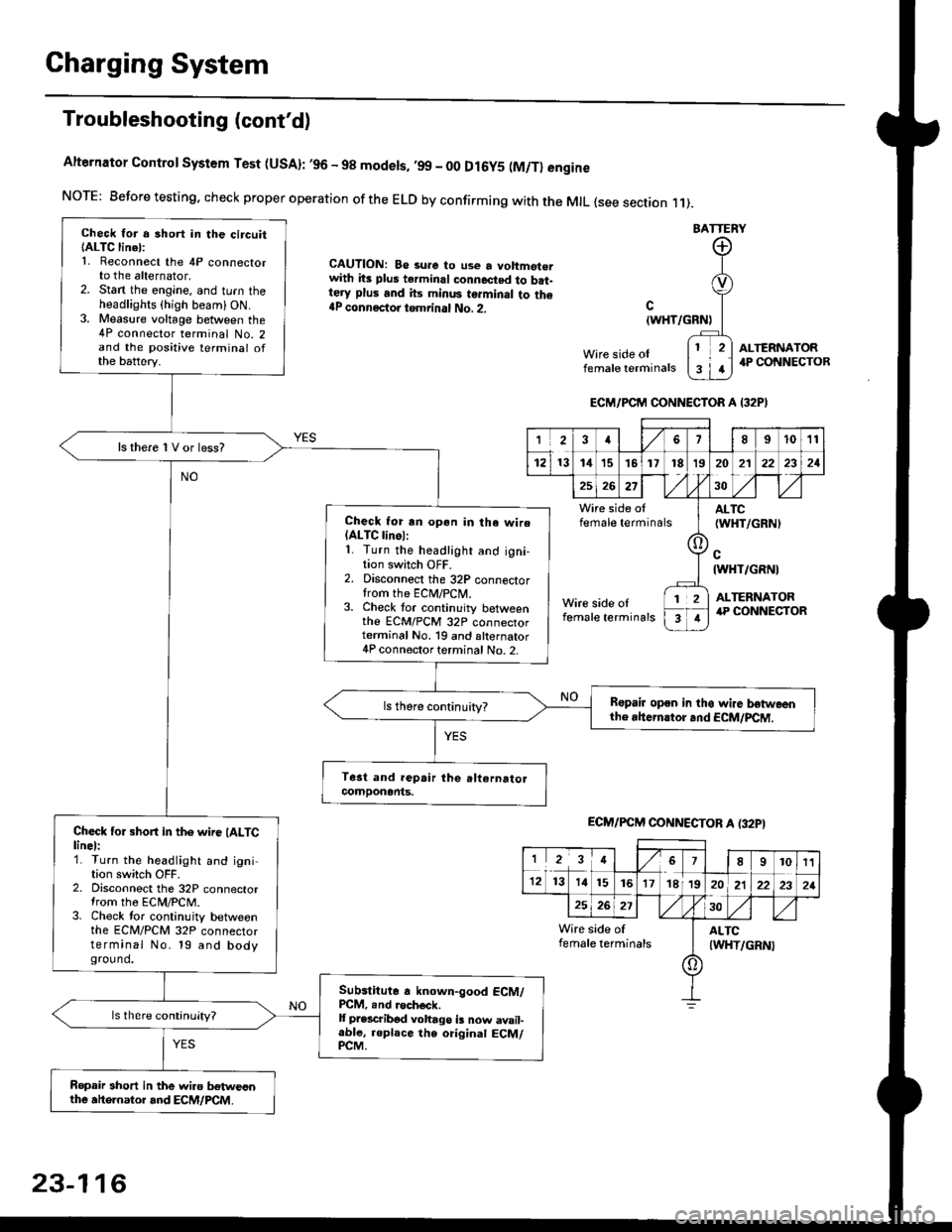
Charging System
Troubleshooting (cont'd)
Alternator Control System Test (USA): ,96 - 98 modets, ,99 _ 00 Dl6y5 (M/Tl engine
NorE: Before testing. check proper operation of the ELD by confirming with the MrL {see section r 1).
BATTERY
CAUTION: Be 3ure to use a voltmot€.with its plus terminal connected to b.t-tery plus and its minus terminal to the{P connectoi tgmrinal No. 2.c
{WHT/GRNt
Wire side oIfemale terminals
ALTERNATOR.P CONNECTOB
Check for a 3hort in the circuitIALTC linel:1. Reconnect the 4P connectorto the alternator,2. Stan the engine, and turn theheadlights {high beam) ON.3. Measure voltage between the4P connector terminal No. 2and the positive terminal ofthe battery.
ls there 1V or less?
Check for rn opon in tha wire(ALTC linol:1. Turn the headlight and igni-tion switch OFF.2. Disconnect the 32P connectortrom the ECM/PCN4.3. Check tor continuity betweenthe ECM/PCM 32P connectorterminal No. 19 and alternator4P connector terminal No. 2.
Bspair open in thg wire lrstweenthe rhern.tor .nd ECM/PCM.
Check for short in the wire (ALTClinel:1. Turn the headlight and ignition switch OFF.2. Disconnect the 32P connectortrom the ECM/PCM.3. Check tor continuity betweenthe ECM/PCM 32P connectorterminal No. 19 and bodyground.
Subslitute a known-good ECM/PCM, .nd .och6ck.It p.escribod vohago i! now avail-able, replace the original ECM/PCM.
Ropair 3hort in the wiro betweonthe ahe.nator and ECM/PCM.
ECM/PCM CONNECTOR A I32PI
'Ia18I1011
121314151718t9
7
202'l2221
262730
Wire side offemale terminalsALTC(WHT/GRNI
c{WHT/GRNI
ALTERNATORWire side oIfemale terminals
([l
T
12
1
ECM/PCM CONNECTOB A (32PI
I23478910t1
1213 14151617182021222321
262730
Wire side of I AITCfemate terminats
A
(WHT/GRN|
23-116
Page 1587 of 2189

-
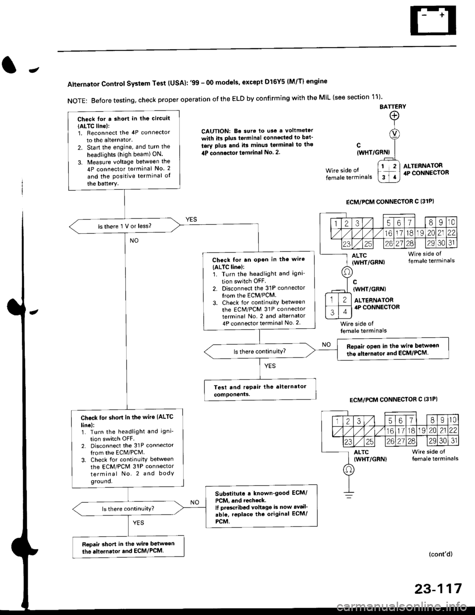
Alternator Control System Test {USA}: '99 - 0O models, except Dl6Y5 {M/T} engine
NOTE: Before testing, check proper operation ofthe ELD by confirming with the MIL (see section 11)'
BATTERY
CAUTION: Be sura lo use a voltmeter
with its plus te.minal conneqted io bat-
tery plus and it3 minus tgrminal to ths
4P connoctot tomrinal No. 2.
Wire side of
female terminals
c(WHT/GRNI
wire side offemale terminals
ALTERNATOR.P CONNECTOR
ECM/PCM CONNECTOR C 13lPI
ECM/PCM CONNECTOR C (31PI
(cont'd)
23-117
Check lor a sho.t in the circuit
{ALTC line):1, Beconnect the 4P connector
to the alternator.
2. Start the engine, and turn the
headlights (high beam) ON.
3. Measure voltage between the
4P connector terminal No. 2
and the Positive terminal of
the battery.
ls there 1 V or less?
Chcck for rn opon in the wire(ALTC lin6l:1. Turn the headlight and igni-
tion switch OFF
2. Disconnect the 31P connector
trom the ECM/PCM.
3. Check for continuity betlveen
the ECM/PCM 31P connectorterminal No. 2 and alternator
4P connector terminal No. 2
Repair opcn in the wire botweon
the alternstoi.nd ECM/PCM.ls there continuity?
Check tor short in the wire IALTC
line):1. Turn the headlight and igni-
tion switch OFF2. Disconnect the 31P connector
from the ECM/PCM.
3. Check for continuity between
the ECM/PCM 31P connector
terminal No. 2 and body
ground.
Substitute a known'good ECM/
PCM, and recheck.It prscribed voltagg is now avail'
abl€, replace tho original ECM/
PCM.
Raoair short in the wite between
the alle.nator and ECM/PCM,
1235618I10
/11611lo191 zo2122
23252621?82930JI
ALTC Wire side of(WHT/GRN) female terminals
o
Page 1602 of 2189
Gauge Assembly
(Wnh lachomolgr)
I cNfldt--]I CONTRoL II MODULE
I 0cM) :
tvl
i.ll
|
-i;,
i
TURN SIGNAUHAZAROWARNINGswtTcH
Circuit Diagram {cont'd)
Fh"lurous @)- BLrcwHT + BLKryEL
fi'Sfvrous 16r.- veLPAGE
RIGHT
V
IGR&ryE
LEFT
V
I
No.s (104)FUSE
V
IBEO/GRN
lru
8LU4RE0
ABSCONTROLUNIT
-rl
eLui'rvrr
G401G402G401G442
23-132
Page 1610 of 2189
Vehicle Speed Sensor (VSSI
Troubleshooting
Before testing, inspect the No. 15 (7.5 A) fuse in the under-dash fuse/relay box.
TEST HARNESSOTLAJ _ PT3O2OAREO TEST HARNESSCLIP
PROTECTIVETAPE
TEST HARNESSOTLA' . PT3O2OA
(To next page)
Test the BLK wire:1. Disconnect the 3P connectorfrom the vehicle speed sensor(vss).
2. Connect the test harness(07LAJ PT30200) only to theengine wire harness,3. Connect the RED test harnessclip to the positive probe of a
4. Check for continuity betweenthe RED test harness clip andbody ground.
Repair opon in the BLK wireb€twe€n the VSS and G101.ls there continuity?
Te3t the BLK/YEL wire:1. Connect the WHT test harnessclip to the positive probe of avoltmeter, and connectthe REDtest harness clip to the negativeprobe.2. Turn the ignition switch ON {ll).
Repair open in iho BLK/YEL wirebetween the VSS and the under-d6sh tuse/relav box.
vss
GRN TEST HARNESS
RED TEST HARNESS
WHT TEST HARNESS CLIP
23-140
Page 1611 of 2189

J
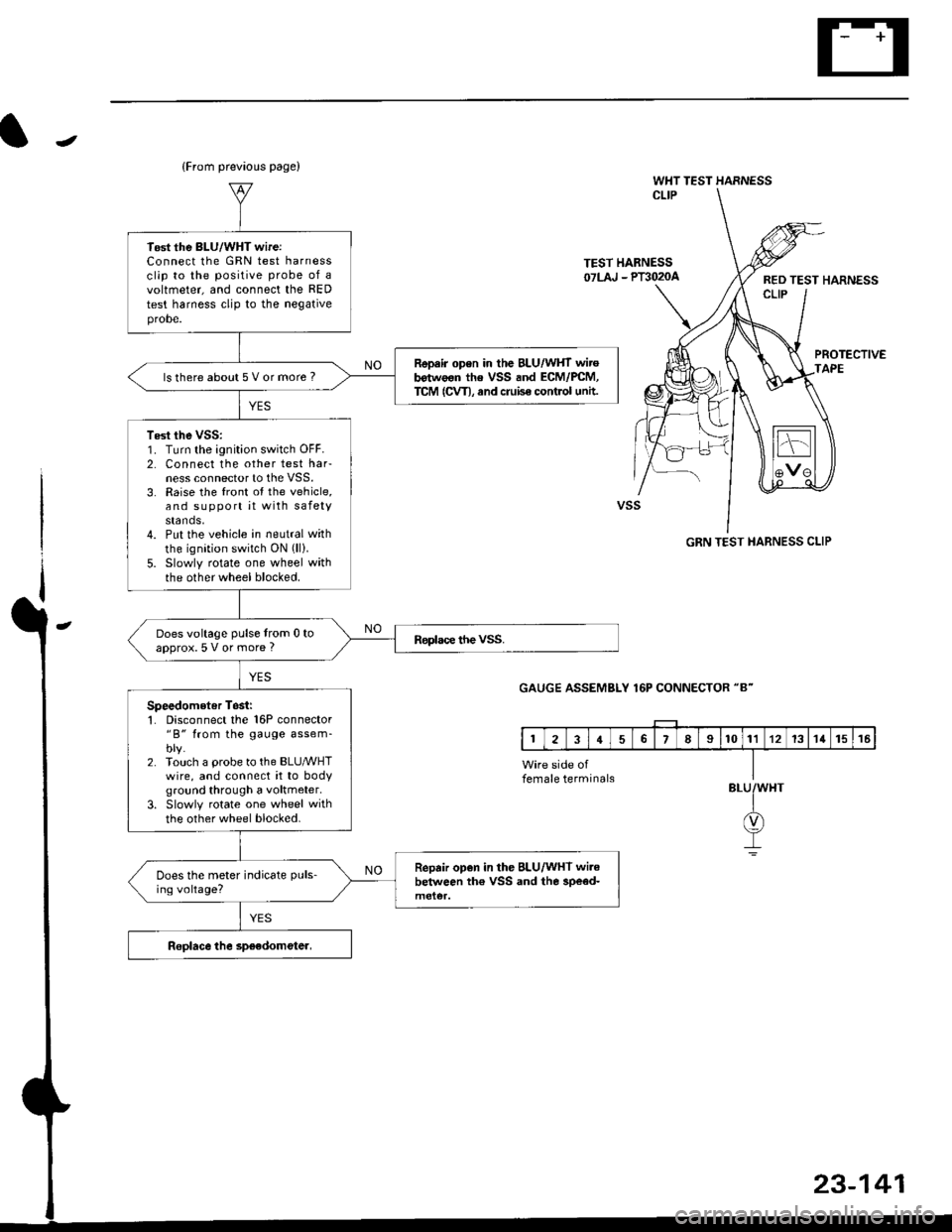
(From prevaous page)
WHT TEST HARNESSCLIP
TEST HABNESS07LAJ - Plil020aRED TEST HARNESSCLIP
PROTECTIVEAPE
GRN TEST HARNESS CLIP
GAUGE ASSEMBLY 16P CONNECTOR "8"
BLU
23-141
Tost the BLU/WHT wireiConnect lhe GRN test harnessclip to the positive probe of avoltmeter, and connect the RED
test harness clip to the negativeprobe.
Repair open in the BLU/WHT wirob€twoon the VSS and ECM/PCM,TCM (CVT), and cruise control untt.ls there about 5 V or more ?
Test the vss:1. Turn the ignition switch OFF.2. Connect the other test harness connector to the VSS.3. Raise the front ot the vehicle,and support it with safetystands,4. Put the vehicle in neutral with
the ignition switch ON (ll).
5. Slowly rotate one wheel withthe other wheel blocked.
Does voltage pulse from 0 toapprox.5 V or more ?
Speedometer Tosii'1. Disconnect the 16P connector"B" from the gauge assem-blv.2. Touch a probe to the BLUMHTwire, and connect it to bodyground through a voltmeter.
3. Slowly rotate one wheel with
the other wheel blocked.
Repair open in the BLU/WHT wi.ebelween th€ VSS and the 3pe€d-Does the meter indicate puls-
ing voltage?
female terminals
Page 1615 of 2189
J
UNDER HOOD FUSARELAY BOX
No 41 (80A) N0.42 (404)
GFNWHT
WHT/GFN
UNOEF,DASHFUSE/RELAY80x
SHIFT LOCKsoLENO|0(O,l : UNLoCK)
I
5
53 INTERLOCK CONTFOL IJNIT
BLK
I
G401G402
GRNAVI{I GR}.//WHT
rl
JI
VIBRAI(E LIGHIS IcRUrsE coNTROL UNIT IABS CONTROT, UNIT IrcM (cw) I
YEL
lr
rEt
till
l'YEUBLK
M GEARPOStT|ONINDICATOF
f7
I
] SENSOR
f7
IRED/BLK
WHT/BLK
II
t,/P1 ennr
Vl$"ilT?l*r e,."o rlr I PUsh bdon frsn€o I| Inpos on B )BLK
II
I:
G401G402
KEY llTNTEnLOCK | |swrTcH I I
KEY INTERLOCK CIRCUIT
GFNWHT
POSTTTONswlTcH(Clos€d : In posilioa lll )
23-145
Page 1621 of 2189
JCircuit Diagram
A/TUNDER HCCD FUSE BELAY BOX
PCi\4
V
I
I.T Gq
GNIT ONSW TCHTJNDEF OASH
'^a" fr-.-r^ """- *
-l
6l\
U__t- -t ir_i ;_P _+irh-
\:f
; h,:_
ArT GEAR POS TION IND CATOF (n lhegauge assembyl
A13412
YEL
f333{'*)
f7
IRED,ELKPCM
V
IGRNlBLK
I
l-
6LK 8LU
12
f7 f7 fl
ItlWHT YEL GFN
rl\4 l765 2 (Nol used)
{'}'}'1,
I
A._. --An i
t.--it-
Lrl9_PNK-
A'T GEARBLK
AIT GEAR POSTON NDLCA1ORD MM]NG CIRCUT
II
I
DASH L GHTSBRIGHTNESSCONTFOLLER
f7
ISLU\. -Ti i:5AFL]SE
V
IF:I BLK
I
l',
ll^,.,^,1L,-N pos r oN II(d].ONSCLEI
lYi:il |
Il--f'-
IRED
I
I
DASH L GHTSBB GHTNESSCONTFOLLER
BLK
I
oio,G402
23-151