Page 214 of 2189

Cylinder BlockPiston Pins
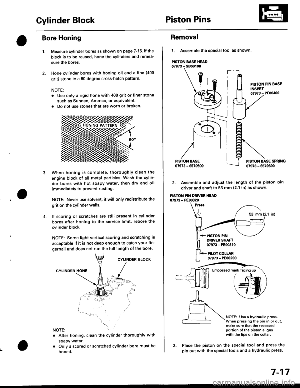
Bore Honing
1.Measure cylinder bores as shown on page 7-16. lf the
block is to be reused, hone the cylinders and remea-
sure the bores.
Hone cylinder bores with honing oil 8nd a fine (400
grit) stone in a 60 degree cross-hatch pattern.
NOTE:
. Use only a rigid hone with 400 grit or finer stone
such as Sunnen, Ammco, or equivalent.
. Do not use stones lhat are worn or broken.
When honing is complete, thoroughly clean the
engine block of all metal particles. Wash the cylin-
der bores with hot soapY water, then dry and oil
immediately to prevent rusting.
NOTE: Never use solvent. it will only redistribute the
grit on the cylinder walls.
lf scoring or scratches are still present in cylinder
bores after honing to the service limit, rebore the
cylinder block.
NOTE: Some light vertical scoring and scratching is
acceptable if it is not deep enough to catch your fin-
gernail and does not run the full length of the bore.
CYLINOES BLOCK
CYLINDER
NOTE:
. After honing, clean the cylinder thoroughly with
soapy warer.
. Onlv a scored or scratched cylinder bore must be
noneo.
Removal
l. Assemble the special tool as shown.
PISTON BASE HEAD07973 - SBtx)too
ft
PISTON PIN BASE
INSERT01973 - PE00'0)
ptn
NOTEi Us6 a hydraulic press.When pressing the pin in or out.make sure that the recesssdportion of the piston alignswith the lips on the collar.
rg
g\
lj*N*,""
2. Assemble and adjust the length of the piston
driver and shaft to 53 mm (2.1 inl as shown.
PISTON PIN DRIVER HEAD07973 - PE00320
Proat
0
PISTON PINDRIVER SHAFT0t973 - PEqr310
PILOT COLLAR07973 - PE00200
3. Place the piston on the sp€cial tool and press the
pin out with the special tools and a hydraulic press.
Emboss6d mark facing up
7-17
Page 607 of 2189
Synchro Sleeve,
Synchro Hub
MBS Shift Piece InsPection
1. Measure the width of the MBS shift piece.
Standard; 6.9 - 7.1 mm 10 272 - 0.280 inl
Service Limit: 6.8 mm {0.268 inl
lf the width of the MBS shift piece is less than
service limit, replace the MBS shift piece'
t
I nspection/l nstallati on
'1.lnspect gear teeth on all synchro hubs and synchro
sleeves tor rounded off corners, which indicate
Install each synchro hub in its mating synchro
sleeve, and check for freedom of movement.
NOTE: lf replacement is required, always replace
the synchro sleeve and synchro hub as a set.
SYNCHROSLEEVE
When assembling the synchro sleeve and synchro
hub, be sure to match the three sets of longer teeth
(120 degrees apart) on the synchro sleeve with the
three sets of deeper grooves in the synchro Hub
CAUTION: Do not install th€ sYnchro sleeve with
its longsr t€sth in the synchro hub slots bocause ii
will damage ths spring ring.
LONGER TEETH
13-27
Page 660 of 2189
Synchro Sleeve, Synchro Hub
Inspection
1,Inspect gear teeth on all synchro hubs and synchro
sleeves for rounded off corners. which indicates
Install each synchro hub in its mating synchro
sleeve and check for freedom of movement.
NOTE: lf replacement is required, always replace
the synchro sleeve and synchro hub as a set.
Installation
When assembling the synchro sleeve and synchro hub,
be sure to match the three sets of longer teeth (120
degrees apart) on the synchro sleeve with the three sets
of deeper grooves in the synchro hub.
CAUTION: Do noi install tho synchro sleeve with its
longer toeth in the synchro hub slots, because it will
damage the spring ring.
SYNCItROSLEEVCLONGER TEETH
13-80
Page 670 of 2189

Mainshaft Thrust Clearance
Adjustment (cont'd)
13. Check the thrust clearance in the manner describedoetow.
CAUTION: Measuremenl should be made at roomtempetature.
a. Slide the mainshaft base over the mainshaft.
MAINSHAFT EASE07GAJ - PG20.130
b. Attach the mainshaft holder to the mainshaft asfollows:
NOTE:
. Back-out the mainshaft holder bolt and loosenthe two hex bolts.. Fit the holder over the mainshaft so its lip istowards the transmission.. AIign the mainshaft holder.s Iip around thegroove at the inside of the mainshaft splines,then tighten the hex bolts.
MAINSHAFT HOLOERBOLT
MAINSHAFT
[--F-e
l6fffi l
rx| - \-/ I/ Borrs
ff
MAINSHAFTHOLDER07GAJ - PG20110
MAINSHAFT BASE07GAJ - PG20130
13-90
c. Seat the mainshaft fully by tapping its end with aplastic hammer.
d. Thread the mainshaft holder bolt in untjl it justcontacts the wide surface of the mainshaft base.
e. Zero a dial gauge on the end ofthe mainshaft.
f. Turn the mainshaft holder bolt clockwise; stooturning when the dial gauge has reached itsmaxtmum movement. The reading on the dialgauge rs the amount of mainshaft end Dlav.
CAUTION: Turning tho mainshaft holder boltmore than 60 degrees after the needle of the dialg€uge stops moving may damage the transmis_ston.
07cAJ _ PG20110
g. lf the reading is within the standard, the clear-ance is correct.
lf the reading is not within the standard. recheckthe shim thickness.
Standard: 0.11 - O.18 mm {0.004 - 0.007 in}
DIAL GAUGE
Page 1046 of 2189
l.
11. Set the double loop band onto the boot and dynam-
ic damper with the band end toward the front ot the
vehicle.
LOOP BANO
Pull up the slack in the band bY hand
Mark a position on the band 10 - 14 mm {0 4 - 0 6
in) from the cliP.
DOUBLE
,
1')
13.
CLIP
Ip
14.
15.
Thread the free end of the band through the nose
section of the boot band tool and into the slot on
the winding mandrel.
Place a wrench on the winding mandrel of the boot
band tool, and tighten the band until the mark you
made on the band meets the edge of the clip.
Mark on band.
Lift up the boot band tool to bend the free end
the band 90 degrees, then center-punch the clip'16.
(cont'd)
16-13
(KD-3191 or equivalent)
HAMMER
Page 1252 of 2189
Doors
Glass Adjustment {cont'd)
c. Tighten the roller guide bolts.
d. Loosen the front channel bolts.
e. Lower the glass.
f. Push the front channel against the glass, then
tighten the mounting bolts.
MOUNTINGBOLT
3. Check that the glass moves smoothly.
4. Raise the glass fully and check for gaps.
5. Check the glass operation.
NOTE: Check that the glass contacts the glass run
channel evenly.
WEATHERSTRIP
GLASS
U
-\,
20-22
6. Check for water leaks.
Spray water over the roof and on the sealing area
as shown.
NOTE:
. Adjust the water pressure as shown.
. Do not squeeze the tip of the hose.
0.5 m {1.6ft)
HOSE
Attach the plastic cover, then install the door panel
(see pages 20 4, 10, 16).
Install the regulator handle so it points forward and
up at a 45 degree angle with the glass closed.
Forward -
1.
HOSE
300 mm {11.8 in)
Page 1746 of 2189

Precautions/Procedu res
SRS Unit Precautions
Take extra care when painting or doing body work inthe area below the dashboard. Avoid direct exDosureof the SRS unit or wiring to heat guns, welding. orsprayang equipment.
Disconnect the airbag connector(s) before discon-necting SRS harness connectors (see page24-1|1J.
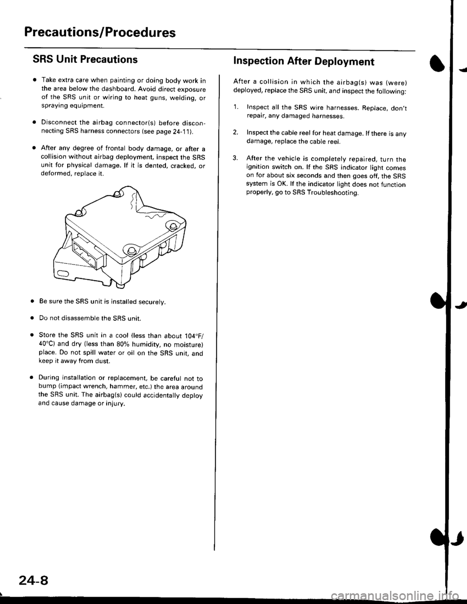
After any degree of frontal body damage, or after acollision without airbag deployment, inspect the SRSunit for physical damage. lf it is dented. cracked, ordeformed, replace it.
Be sure the SRS unit is installed securely.
Do not disassemble the SRS unit.
Store the SRS unit in a cool (less than about 104.F/40"C) and dry (less than 80% humidity, no moisture)place. Do not spill water or oil on the SRS unit, andkeep it away from dust.
During installation or replacement, be careful not tobump (impact wrench, hammer, etc.) the area aroundthe SRS unit. The airbag(s) could accidentally deptoyand cause damage or injury.
24-8
Inspection After Deployment
After a collision ln which the airbag(s) was (were)
deployed, replace the SRS unit, and inspect the following:
1. Inspect all the SRS wire harnesses. Replace. don,trepair, any damaged harnesses.
2. Inspect the cable reel for heat damage. lf there is anydamage, replace the cable reel.
3. After the vehicle is completely repaired, turn theignition switch on. lf the SRS indicator light comeson for about six seconds and then goes off. the SRSsystem is OK. lf the indicator light does not functionproperly, go to SRS Troubleshooting.