1996 HONDA CIVIC torque
[x] Cancel search: torquePage 2 of 2189

INTRODUCTION
How to Use This Manual
This manual contains information for the 1996 - 2000 ClVlC. lt is
divided into 24 sections. The first page of each section is marked
with a black tab that lines up with its corresponding thumb index
tab on this page and the back cover. You can quicklY find the first
page of each section without looking through a tull table ol con_
tents. The symbols printed at the top corner of each page can also
be used as a quick reference system.
Each section includesl
1. A table of contents, or an exploded view index showing:
. Parts disassemblY sequence.
. Bolt torques and thread sizes.
. Page references to descriptaons in text
2. Disassembly/assembly procedures and tools.
3. Inspection.
4. Testing/troubleshooting.
5. Repair.
6. Adjustments.
Special Information
!@ Indicates a sttong possibility of sover. perconal iniurY
or loss ol lite if in3tructions are not follow€d.
GAUTION: Indicaiqs a possibility ot p€lsonal injury or 6quipm.nt
damage il instiuc'tions are not followod
t Noncali-. pu.po.. ot thes6 messages is to help provent demage lo lhe
vehicle, other property, or the €nvironment.
NOTE: Gives helpful information.
CAUTfON: Detaifed descriptions ol standard workshop p.oceduro3.
safoty principles and servico operations are not included. Pleaso
note that this manual contain3 wetnings and cautions against
some sp6cific sGrvic€ methods which could cause PERSONAL
INJURY, damage a vohicle or make il unsafe. Ploase undorstand
that these warnings cannot covsr all conceivable weys in which
service. whelher or not iocommgndod bY HONDA. mighi bo done,
or ol tho possiblG hazardou3 consgquonces of ev€aY conceivablg
way, nor could HONDA invqstigato all 3uch way3. AnYono using
sgrvice procedures or lools, whethei or nol rGcommendod bY
HONDA, must srtisty hifisetf thoroughlylhat nohher pefsonal sefety
nor vehiclc satsty will be reopardi2ed.
All intormation contained in this manual is based on the latest prod
uct information available at the time oI printing We reserve the
right to make changes at any time without notice No part of this
publication may be reproduced, stored in retrieval system, or trans'
mitted, in any form by any means, electronic, mechanical, photo
copying, recording, or otherwise, without the prior written permis-
sion of the publisher. This includes text, figures and tables.
*Transaxle
ds
First Edition 8/99 1848 PagesAll Right Reserved
HONOA MOTOR CO., LTD.
Sorvico Publication Offico
As sections with * include SRS components;
sDecial precautions are lequired when servlclng
*Electrical't
*SRSSRS
Page 53 of 2189

Standards and Service Limits
Manual Transmission S40 - Section 13
MEASUREMENT
Capacity | (US qt, tmp qt)
End playDiameter of ball bearing contact area A(Transmission housing side)Diameter of 4th, 5th gear contact area BDiameter of 3rd gear contact area CDiameter of ball bearing contact area D(Clutch housing side)Bunout
STANDARD INEW}'1.9 (2.0, 1.7)for overhaul1.8 (1.9, 1.6) for oitchange
0.11 0.18 (0.004 _ 0.007)21.987 - 22.000 (0.8656 0.8661)
26.980 26.993 (1.0622 _ 1.0627)33.984 34.000 (1.3380 1.3386)25.917 - 25.99011.0227 1.0232)
0.02 (0.001) max.
SEBVICE LIMIT
ro
MainshaftAdjust21.930 (0.8634)
26.930 ('1.0602i33.930 (1.3358)
25.92011.0205)
0.05 (0.002)
39.07 ('r.538)
0.33 {0.013)0.31 (0.012)
30.15 (1.187)
30.05 (1.183)
37.07 {1.459)0.31 (0.0'12)
28.35 (1.116)
LrO
39.009 39.025 (1.5358 1.5364)0.06 0.21 (0.002 0.008)0.06 0.19 (0.002 0.007)30.22 30.21 (1.190 1.192)30.12 - 30.17 (1.186 1.188)
37.009 37.025 (1.4570 _ 1.4577)0.06 - 0.19 (0.002 - 0.007)28.42 - 2a.47 11.119,1.1211Countershaft Diameter of needle bearing contact area ADjameter of lst gear contact area gDiameter of ball bearing contact area CRunout
30.000- 30.015 {1.181 1 - 1.1817)35.984 - 36.000 (1.4167 1.4173)24.980 24.993 (0.9835 - 0.9840)0.02 (0.001)max.
29.950 (1.1791)3s.930 r.4146)24.930 (0.9815)0.0s (0.002)
End play (When tightened by the specified torque)Thickness
41.009 - 41.025 ('�t.6145 1.6152)0.03 0.10 (0.001 _ 0.004)30.41 30.44 (1.197 - 1 198)
41 .01 11.617J0.22 (0.009)
30.36 (1.195)
gear End ptay (When tightened by the specified torque)44.009 - 44.025 (1.7326 1.7333)0.04 - 0.12 (0.002 - 0 005)31.91 31.96 (1.256 1.258)
44.01 11.t35)0.24 (0.009)
31.85 (1.2s4)
33.04 {1.301)38.93 (1.533)32.01 (1.260)
27.06 (1.065)
33.93 (1.336)
3r.93 {1.257)22.81 (0.898)
23.51 (0.926)
15.08 (0.594)
0.14 (0.006)
0.4 (0.016)
0.16 (0.006)
o.6210.0244112.78 (0.5031)
t.D.o. D.Length
33.000 - 33.010 (1.2992 1.2996)38.989 39.000 11.53s0_ 1.53s4)32.03 - 32.06 tl.261 - 1.2621Spacer collar(Mainshaft 4thand 5th gear)
Beverse rdler gear LD.Gear to reverse gear shaft cjearance
27.002 27.012 (1.0631 _ 1.0635)33.989 - 34.000 (1.3381 - 1.3386)3r.989 - 32.000 (1.2594 1.2598)22.83 - 22.86 (0.899 0.900)23.53 23.56 (0.926 - 0.928)
rs.016 15.043 (0.5912 _ 0.5922)0.032 0.077 (0.0013 _ 0.0030)Ring-to gear clearance {Ring pushed against gear)0.73 - 1.l8 (0 029 - 0.046)Fork finger thickness
Fork to-synchro sleeve clearance
lsv2nd/sth I 6.2 - 6.410.244 - O.ZS2)3rdl4th 7.4 i.6lO 2g1 O 2ggt0.35 - 0.65 (0.014 - 0.026)Beverse shitt fork Fork pawl groove widthFork to-reverse idler gear clearanceL groove widthFork'to-5th/reverse shift piece pin clearance
12.7 - 13.0 (0.50 _ 0.51)0.5 1. t (0.020 0.043)7 .05 - 7 .25 tO.21A - 0.28510.05 0.35 (0.002 0.014)Sh ift a rm A tnner diameter of sh ift arm C contact ffiShift arr14-go "L;L ".m C clearance13.05 13.13 (0.514 0.517)0.05 - 0.23 (0.002 _ 0.009)Inner diameter of shift arm B shaft contact pointShift arm 8-to shaft clearanceShift arm B to-shift piece clearanceDiameter of shift piece contact point
13.973 - 14.000 (0.5501 0.5512)0.013 0.070 (0.0005 _ 0.0028)0.2 - 0.5 {0.008 0.020)12.9 13.0 (0.508 - 0.512)MBS Shift prece Diameter of pin6.9 7 .1 \O.27 0 2A)
0.095 (0.004)
0.14 (0.006)
Adjust with shim
Differenlial carrier Pinion shaft bore diameterCarrier-to pinion shaft clearanceDriveshaft bore diameterCarrier to,driveshaft clearance
18.010 18.028 (0.7091 _ 0.7098)0.023 0.057 (0.0009 - 0.0022)26.025 26.04s {1.0246_ 1.0254)0.045 - 0.086 (0.0018 0.0034)BacklashPinion gear bore diameterPinion gear-to pinion shaft clearance
0.05 0.15 (0.002 0.006)18.042 - 18.066 (0.7103 _ 0.7113)0.055 - 0.095 {0.0021 _ o.oo37)
0 0.1 10 - 0.004)
3-8
LO
Page 54 of 2189
Unit of length: mm (in)
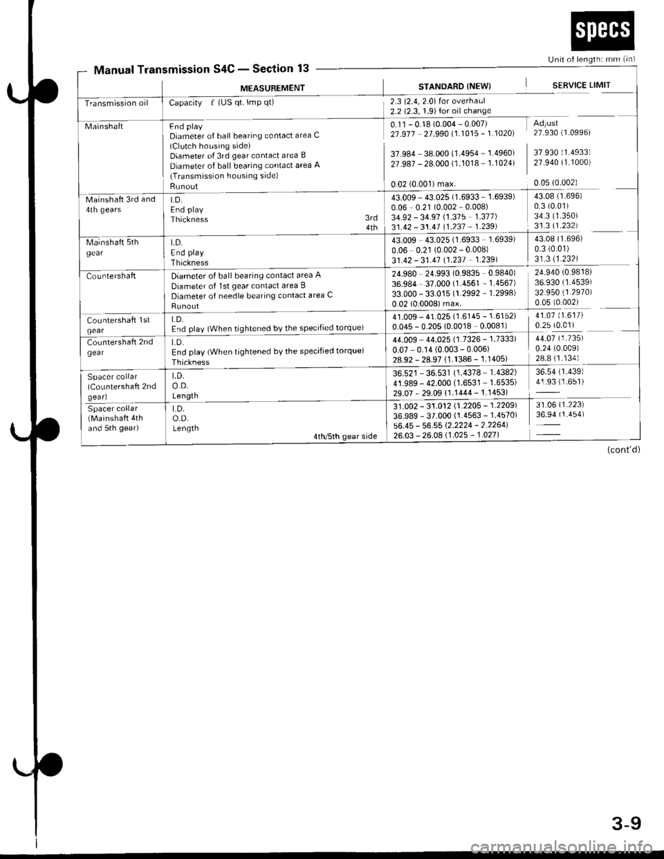
Transmission oil
43.009 43.025 (1.6933 - 1.6939)
0.06 0.21 (0.002 - 0.008)
31.42 - 31.41 \1.231 1.2391
t.D.End play
Thickness
Diameter of ball bearing contact area A
Diameter of lst gear contact area I
Diameter of needle bearing contact area C
Runout
LD.End play {When tightened by the specified torque)
Thickness
LD.o.D.Length
Spacer collar(CoLrntershaft 2ndgear)
Spacer collar(Mainshaft 4thand 5th gear)
LD.o.D.Lengtn
Manual TransmissionS4C - Section 13
M€ASUREMENT
MainshaftFnd plaVDiameter of ball bearing contact area C(Clutch housing side)Diameter of 3rd gear contact area B
Diameter of ball bearing contact area 'q(Transmission housing side)
Runout
Capacity | (US qt, lmp qt)
LD.End play
Thickness
2.3 (2.4,2.0) for overhaul2.2 (2.3, 1.9)for oil change
0.11 - 0.18 (0.004 - 0.007)21 .917 - 21 .990 11.1015 - 1 .10201
37.984 38.000 (1.4954 1.4960)
27.987 - 28.000 (1.1018 1.1024)
STANDARD {NEW)
0.02 (0.001)max.
SERVICE LIMIT
Adtust27.930 (1.0996)
37 930 (1.4933)
27.940 (1.1000)
0.05 (0.002)
Mainshaft 3rd and4th gears
43.009 - 43.025 (1.6933 1.6939)
0.06 - 0.21 (0.002 0.008)
34.92 - 34.91 \1.315 1.311)
31.42 - 31.41 (1.237 1.239)
24.980 24.993 (0.9835 0.9840)
36.984 37.000 (1.4561 - 1.4567)
33.000 - 33.015 (1.2992 - 1.2998)
0.02 (0.0008) max.
3rd4th
43.08 (1.696)
0.3 (0.01)
34.3 ('�t.350)
31.3 11.232)
43.08 (1.696)
0.3 (0.01)
31.311.232)
24.940 (0.9818)
36.930 (1.4539)
32.950 (1.2970)
0.05 (0.002)
41.07 (1.617)
0.25 (0.01)41.009 - 41.025 (1.6145 - 1.6152)
0.045 - 0.205 (0.0018 0.0081)
44.009 44.025 {1.7326 - 1.7333)
0.07 0.14 (0.003 - 0.006)28.92 - 28.97 (1.1386 -'�j.1405)
36.521 - 36.531 (1.4378 1.4382)
41.989- 42.000 (1.6531 - 1.6535)
29.07 - 29.09 11.1444 - 1.1453)
44.07 (1.735)
0.24 (0.009)
28.8 (1.134)
36.54 (1.439)
41.93 (1.651)
31 .0O2 - 31 .012 11 .2205 - 1 .2209'l
36.989 - 37.000 {1.4563 - 1.4570)
56.45 - 56.55 1'2.2224 - 2.2264126.03 - 26.0A 11 .025 - 1 .021 |
31.06 (1.223)
36.94 (1.454)
(cont'd)
3-9
Page 59 of 2189
Standards and ServiceLimits
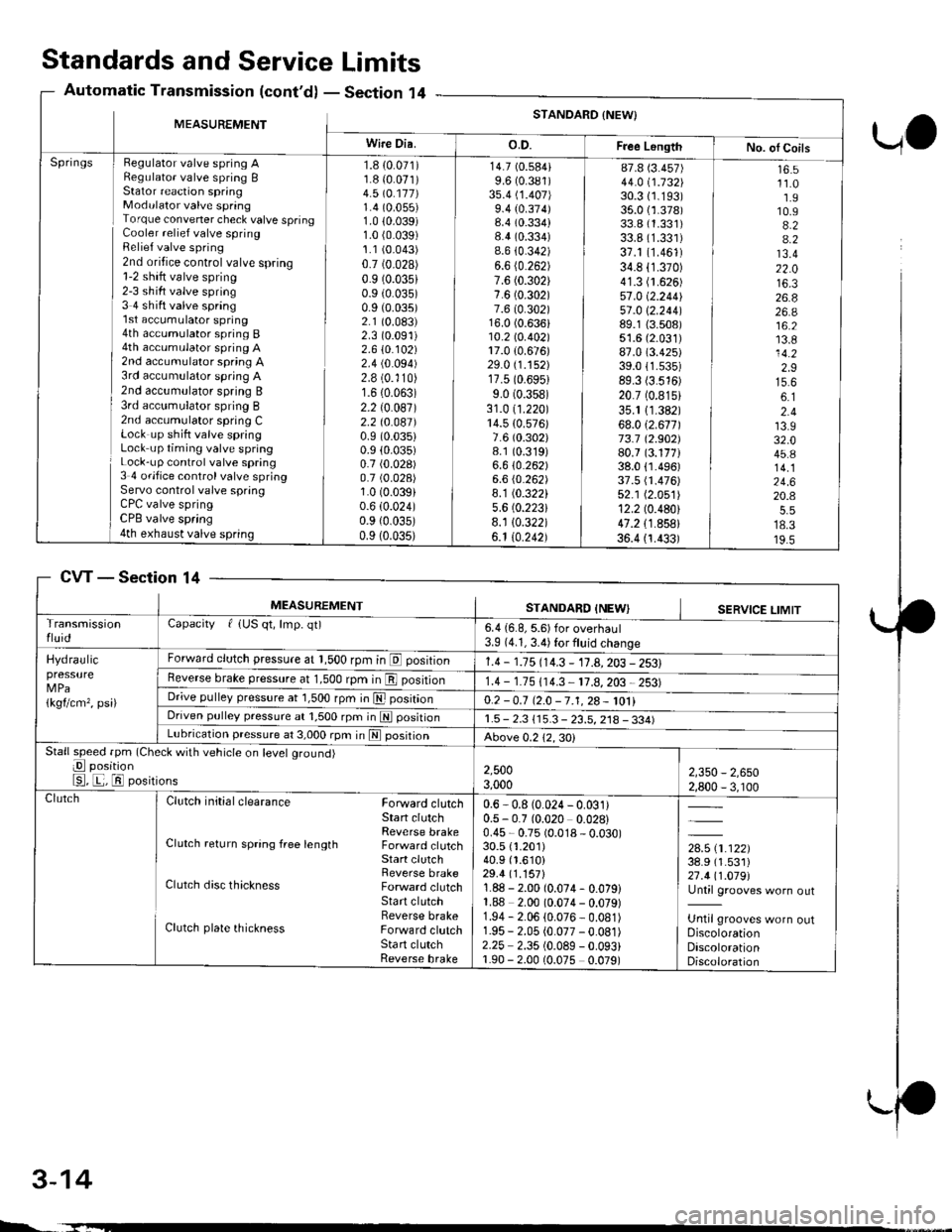
Section '14Automatic Transmission (cont'd)
UO
MEASUREMENTSTANDARD {NEW}
Wire Dia.o.D.Free LongthNo. ol CoilsHegulator valve spring ARegulato. valve spring BStator reaction springModulator valve springTorque convener check valve springCooler relief valve springRelief valve spring2nd oritice control valve spring1-2 shift valve spring2-3 sh ift valve spring3 4 shift valve spring'l st accumulator spring4th accumulator spring B4th accumulator spring A2nd accumulator spring A3rd accumulator spring A2nd accumulator spring B3rd acc!mulator spring B2nd accumulator spring CLock up shift valve springLock up timing valve springLock-up control valve spring3 4 ofifice control valve springServo control valve springCPC valve springCPB valve spring4th exhaust valve spring
Springs1.8 {0.071)1.8 {0.071)4.5 \O.117)1.4 (0.055)
1.0 10.039)1.0 (0.039)
1.1 (0.043)
0.7 (0.028)
0.9 (0.035)
0.9 (0.035)
0.9 (0.035)
2.1 (0.083)
2.3 (0.091)
2.610.102)2.4 (0.094)
2.8 (0.'110)
1.6 (0.063)
2.2 (0.087)
2.2 t0.041)0.9 (0.035)
0.9 (0.035)
0.7 (0.028)
0.7 (0.028)
1.0 (0.039)
0.6 (0.024)
0.9 {0.035)0.9 (0.035)
14.7 (0.584)
9.6 (0.381)
3s.4 (1.407)
9.4 (0.374)8.4 (0.334)
8.4 (0.334)
8.6 {0.342)6.6 (0.262)
7.6 (0.302)
7.6 (0.302)
7.6 (0.302)16.0 (0.636)10.2lo.402l17.0 {0.676)29.0 (1.152)
17.5 (0.6951
9.0 (0.358)
31.0 (1.220)
14.5 {0.576)7.6 (0.302)
8.1 (0.319)
6.610.262)6.6 (0.262)
8.1 (0.322)
5.6 (0.2231
8.1 10.322)6.1 10.242)
87.8 (3.457)
44.0 i.732l'30.3 (1.193)
35.0 {1.378)33.8 (1.331)
33.8 (1.331)
37.1 (1.461)
34.8 (1.370)
41.3 (1.626)
57.0 (2.2441
51 .0 \2.244189.1 {3.508)51.6 (2.031)
87.0 (3.425)
39.011.535)89.3 (3.516)
20.7 (0.815)
35.1 11.382)68.012.671173.7 12.902)80.7 (3.177)38.0 {1.496)37.5 fi.476)52.1 (2.051)
12.2 (0.480)
47.2 {1.858}36.4 {1.433)
16.511.01.910.94.24.213.422.016.326.826.a16.213.814.22.915.66.12.413.932.045.814.124.620.4
18.319.5
CVTSection 14
3-14
MEASUREMENTSTANDARD INEWISERVICE LIMITTransmissionfluidCapacity f {US qt, lmp. qt)6.4 {6.8, 5.6) for overhaul3.9 (4.1, 3.4) for fluid change
Hydraulicpressure
1kgflcm,, psi)
Forward clutch pressure at 1,500 rpm in E position1.4 - 1.15 114.3 - 11.A,203 - 2531Reverse brake pressure at 1,500 rpm in E position1.4 - 1.75 (14.3 11.8,203 2531Dr;ve pulley pressure at 1,500 rpm in E posrtrono.2 -0.7 12.0 -7.1,28- 1011Driven pulley pressure at 1,500 rpm in N positionr.5 - 2.3 115.3 - 23.5, 218 - 334)Lubrication pressure at 3,000 rpm in E posrtronAbove 0.212,30)Stall speed fpm (Check with vehicle on level ground)
E position
E, E, El positions2,5003,0002,350 - 2,6502,800 - 3, r00ClutchClutch initial clearance Forward clutchStart clutchReverse brakeClutch return spring free length Forward clutchStart clutchReverse brakeClutch disc thickness Forward clutchStart clutchReverse brakeClutch plate thickness Forward clutchSta rt clutchReverse brake
0.6 - 0.8 (0.024 - 0.031)0.5 - 0.7 (0.020 0.028)0.45 - 0.75 (0.018 - 0.030)30.5 {1.201)40.9 (1.610)
29.4 (1.157)
1.88 - 2.00 (0.074- 0.079)1.88 2.00 (0.074 - 0.079)1.94 - 2.06 (0.076 - 0.081)1.95 - 2.05 (0.077 -0.081)
2.25 2.35 (0.089 - 0.093)1.90 - 2.00 (0.075 0.079)
,*x.ar}38.9 (1.531)
27.411.019l'Until grooves worn out
Until grooves worn outDiscolorationDiscolorationDiscoloration
L.
Page 66 of 2189
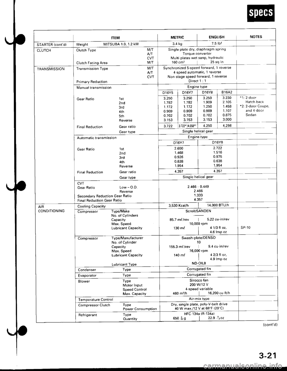
trEM I merntc ENGLISH NorEs
SfAnff n i*nt-i- W"'gf,t MllSUBA r.u, l.z kw r'4 rg
CLUTCHClutch Type
Clutch Facing Area
M/T
CVTM/T
Single plate dry, diaphragm springTorque converterMulti plates wet sanP, hYdraulic160 cm,25 sq in
Synchronized 5-speed forward, 1 reverse
4 speed automatic, 1 reverse
Non stage speed forward, 1 reverse
Direct 1 : 1
TRANSMISSIONTransmission Type
Primary Reduction
M/TArrCW
Manualtransmission
Gear Ratio 1st2nd3rd4th5thReverse
Final Reduction Gear ratio
Gear tYPe
Engine type
D16Y5 | D16Y7 D16Y8 I 81642
3.2501.1821.1120.9090.7023.153
3.2501.1821.1120.9090.7023.153
3.2501.9091.2500.9090.1023.153
3.2302.1051.4581.1070.8753.000
*1:2 doorHatch back+2r 2-door Coupe,and 4 doorSedan
3.122 13.122"11.053" 1 4.250 | 4.266
Single helicalgear
Engine type
D16Y7 | D16Y8Automatic transmission
Gear Ratio 'lst
2nd3rd4thReverse
Final Reduction Gear ratio
Gear tYPe
2.6001.4680.9260.6381.954
2.122
0.9750.6381.954
1.3514.357
cwGear Ratio Low - O.D.Reverse
Secondary Reduction Gear Ratio
Final Reduction Gear Ratio
2.466 0.4492.4661.3334.357
AIRCONDITIONING
Cooling Capacity3,530 Kcal/h14,000 BTU/h
Compressor Type/MakeNo. of CYlindersCaPacitYMax. SpeedLubricant CaPacitY
Scroll/SANDEN
85.7 m//rev 5.22 cu inkev10,000 rpm130 mf 41l3tl oz.
| 4.6 imp ozsP,10
Compressor Type/ManufacturerNo. of CylinderCapacityMax. SpeedLubricant CaPacitY
Lubricant TYPe
Swash-plate/DENso10155.3 mf /rev 9.4 cu_in/rev76,000 rpm140 mf | 4 2l3fl oz,I 4 9lmp ozND'OIL8
Condenser TypeCorrugated fin
Evaporator TyPeCorrugated fin
Elower TyPeMotor InputSPeed ControlMax. CaPacity
Sirocco fan200w112v4 speed variable460 m3/h 16,200 cu ft/h
Temperature Control
Compressor Clutch TyPePower ConsumPtionDry, single plate, PolY-V'belt drive40 W max./12 V at 68'F (20'C)
Refrigerant TyPeouantity
HFC 134a (R'134a)
650 gos | 22.9 isoz
(cont'd )
4 . J-Z I
Page 106 of 2189
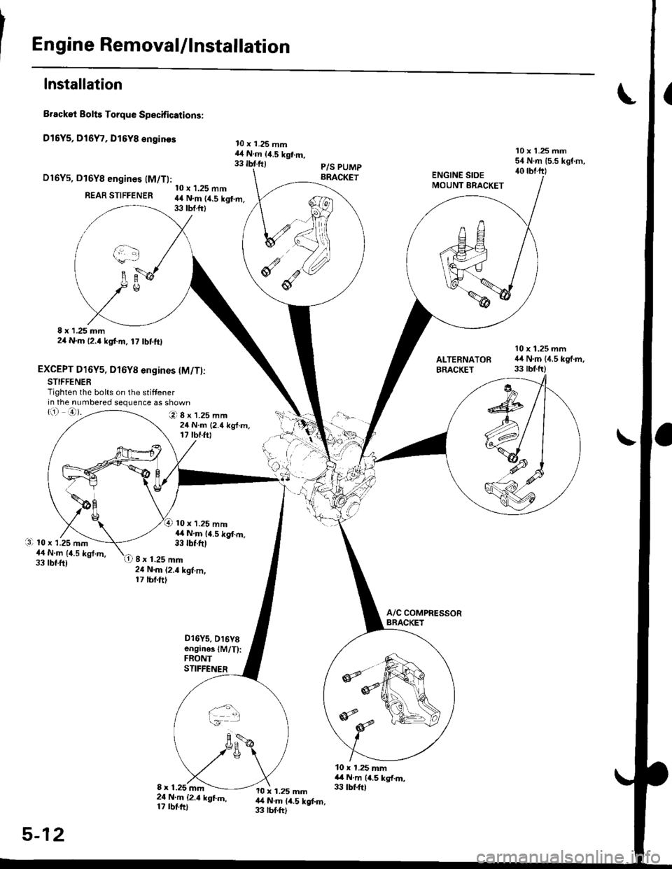
Engine RemovaUlnstallation
Installation
Brackei Bolts Torque Specifications:
Dl5Y5, Dl6Y7, Dl6Y8 €nginss
D16Y5, D16Y8 engines (M/Tl:
REAR STIFFENER
8 x 1.25 mm2/t N.m 12.4 kgf.m, 17 tbf.ftl
EXCEPT D16Y5, Dl6Yg engines lM/T)jSTIFFENERTighten the bolts on the stiffenerin the numbered sequence as shown
10 x 1.25 mm44 N.m 14.5 kgf.m,33 tbf.frt
O8x1.25mm24 N.m {2.4 kg{.m,17 tbr.ftt
10 x 1.25 mm14 N.m 14.5 kgt m,33 tbf.ft)
10 x 1.25 mm44 N.m {4.5 kgt m,33 tbr.ftl
10 x 1.25 mm54 N.m {5.5 kgf.m,40 rbf.ftl
10 x 1.25 mm44 N.m {4.5 kg'f.m,33 tbtftlALTERNATOFBRACKET
li) o).
l3l 10 x 1.25 mm44 N.m {1.5 kgt.m,33 tbt.ft)8 x 1.25 mm24 N.m (2.4 kgf.m,17 tbf.ft)
o16Ys, D16Y8enginoslM/T):FRONTSTIFFENER
10 x 1.25 mm4,4 N.m {4.5 kg{.m.33 tbf.ftl8 x 1.25 mm2{ N.m (2.t kgtm,17 rbtft)
10 x 1.25 mm14 N.m (4.5 kgf.m,33 lbf.ftl
5-12
Page 111 of 2189

Mount and Brackst Bohs/Nuts Torque Value Spocitications:
A: '10 x 1.25 mm
64 N.m {6.5 kgl'm, 47 lbf'ft}
B: 10 i 1.25 mm44 N.m {4.5 kgim,33 lbtft)
C: 12 x 1.25 mm83 N.m 18.5 kgt'm, 61 lbf'ft)
D: 12 x 1.25 mm59 N.m (6.0 ks{ m, 43 lb{ft)
Replace.
REAR MOUNT
SIDE ENGINEMOUNT
Page 123 of 2189
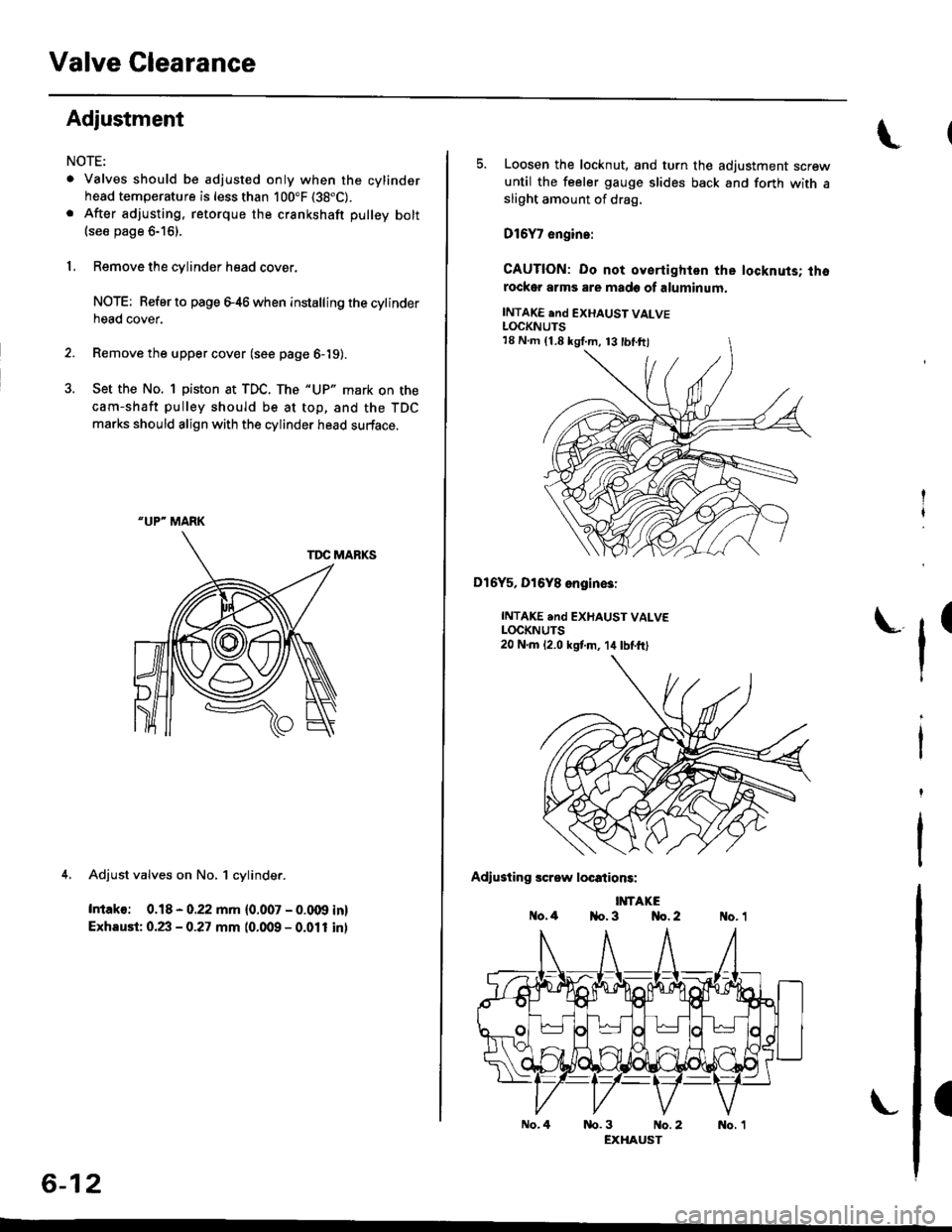
Valve Clearance
Adjustment
NOTE:
. Valves should be adjusted only when the cylindsrhead temperature is less than 100"F (38"C).
. After adjusting, retorque the crankshaft pulley bolt(see page 6-16).
1, Remove the cylinder head cover.
NOTE; Refer to page e46 when installing the cytinderhead cover.
2. Remove the upper cover (see page 6-19).
3. Set the No. 1 piston at TDC. The "UP" mark on the
cam-shaft pulley should be at top, and the TDC
marks should align with the cylinder head surface.
TDC MARKS
4. Adjust valves on No, 1 cylinder.
Intako: 0.18 - 0.22 mm {0.007 - 0.009 in}
Exhaust: 0.23 - 0.27 mm (0.009 - 0.011 inl
"UP" MARK
6-12
No.4
5. Loosen the locknut, and turn the adjustment screwuntil the feeler gauge slides back and forth with asliOht amount of drag,
D16Y7 engin.:
CAUTION: Do not oyertighlen the locknuts; thorockor arms are made of aluminum.
INTAKE end EXHAUST VALVELOCKNUTS
Dl6Y5, Dl6Y8 engin€3:
INTAKE .nd EXHAUST VALVELOCKNUTS20 N.m 12.0 kstm, 14lbtft)
Adiusting screw locations:
IMTAKEo.4 1{o. 3 No. 2
tr'
(
nb.3 No.2 No. 1EXHAUST
18 N.m (1.8 kgI.m, 13 tbl.ftl