1996 HONDA CIVIC fan motor
[x] Cancel search: fan motorPage 66 of 2189
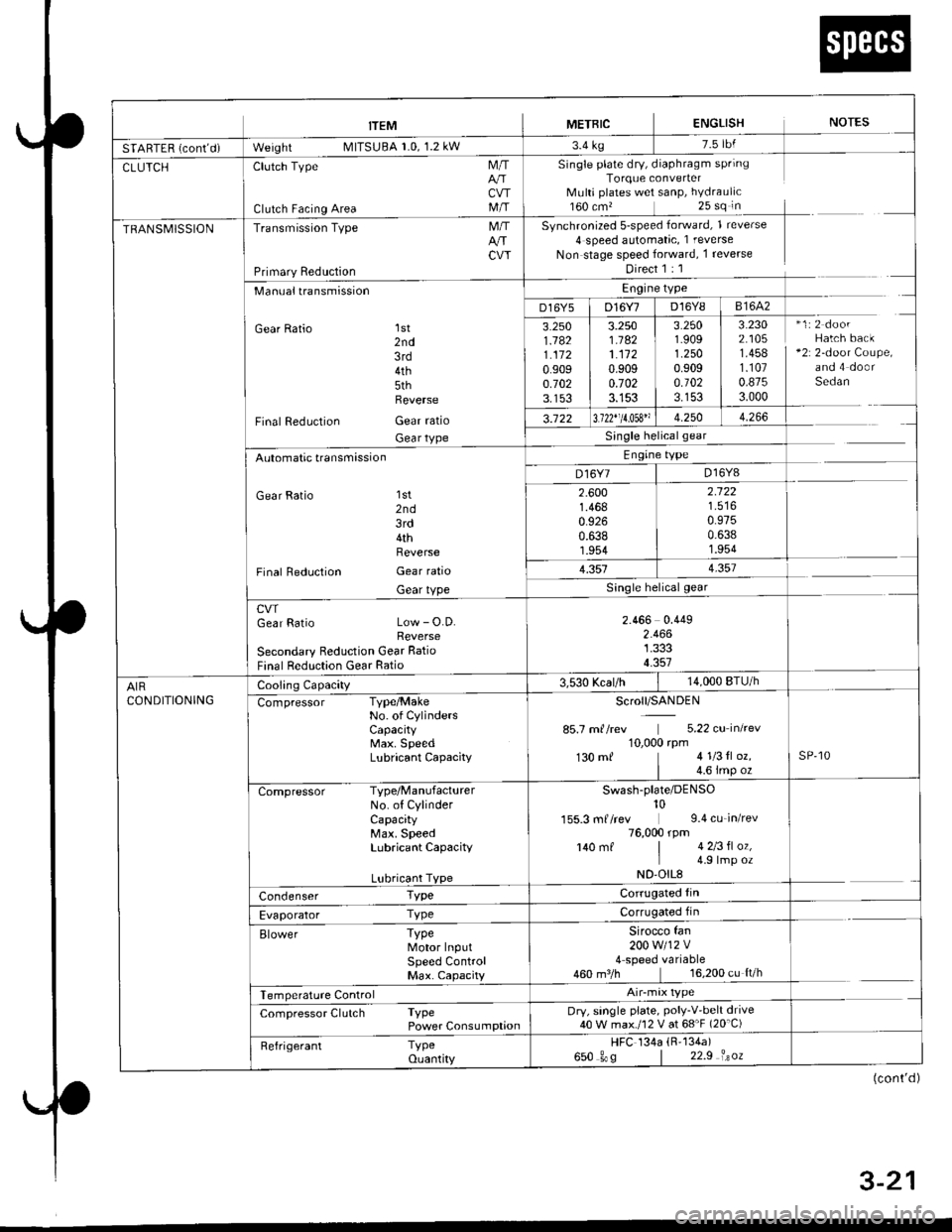
trEM I merntc ENGLISH NorEs
SfAnff n i*nt-i- W"'gf,t MllSUBA r.u, l.z kw r'4 rg
CLUTCHClutch Type
Clutch Facing Area
M/T
CVTM/T
Single plate dry, diaphragm springTorque converterMulti plates wet sanP, hYdraulic160 cm,25 sq in
Synchronized 5-speed forward, 1 reverse
4 speed automatic, 1 reverse
Non stage speed forward, 1 reverse
Direct 1 : 1
TRANSMISSIONTransmission Type
Primary Reduction
M/TArrCW
Manualtransmission
Gear Ratio 1st2nd3rd4th5thReverse
Final Reduction Gear ratio
Gear tYPe
Engine type
D16Y5 | D16Y7 D16Y8 I 81642
3.2501.1821.1120.9090.7023.153
3.2501.1821.1120.9090.7023.153
3.2501.9091.2500.9090.1023.153
3.2302.1051.4581.1070.8753.000
*1:2 doorHatch back+2r 2-door Coupe,and 4 doorSedan
3.122 13.122"11.053" 1 4.250 | 4.266
Single helicalgear
Engine type
D16Y7 | D16Y8Automatic transmission
Gear Ratio 'lst
2nd3rd4thReverse
Final Reduction Gear ratio
Gear tYPe
2.6001.4680.9260.6381.954
2.122
0.9750.6381.954
1.3514.357
cwGear Ratio Low - O.D.Reverse
Secondary Reduction Gear Ratio
Final Reduction Gear Ratio
2.466 0.4492.4661.3334.357
AIRCONDITIONING
Cooling Capacity3,530 Kcal/h14,000 BTU/h
Compressor Type/MakeNo. of CYlindersCaPacitYMax. SpeedLubricant CaPacitY
Scroll/SANDEN
85.7 m//rev 5.22 cu inkev10,000 rpm130 mf 41l3tl oz.
| 4.6 imp ozsP,10
Compressor Type/ManufacturerNo. of CylinderCapacityMax. SpeedLubricant CaPacitY
Lubricant TYPe
Swash-plate/DENso10155.3 mf /rev 9.4 cu_in/rev76,000 rpm140 mf | 4 2l3fl oz,I 4 9lmp ozND'OIL8
Condenser TypeCorrugated fin
Evaporator TyPeCorrugated fin
Elower TyPeMotor InputSPeed ControlMax. CaPacity
Sirocco fan200w112v4 speed variable460 m3/h 16,200 cu ft/h
Temperature Control
Compressor Clutch TyPePower ConsumPtionDry, single plate, PolY-V'belt drive40 W max./12 V at 68'F (20'C)
Refrigerant TyPeouantity
HFC 134a (R'134a)
650 gos | 22.9 isoz
(cont'd )
4 . J-Z I
Page 257 of 2189
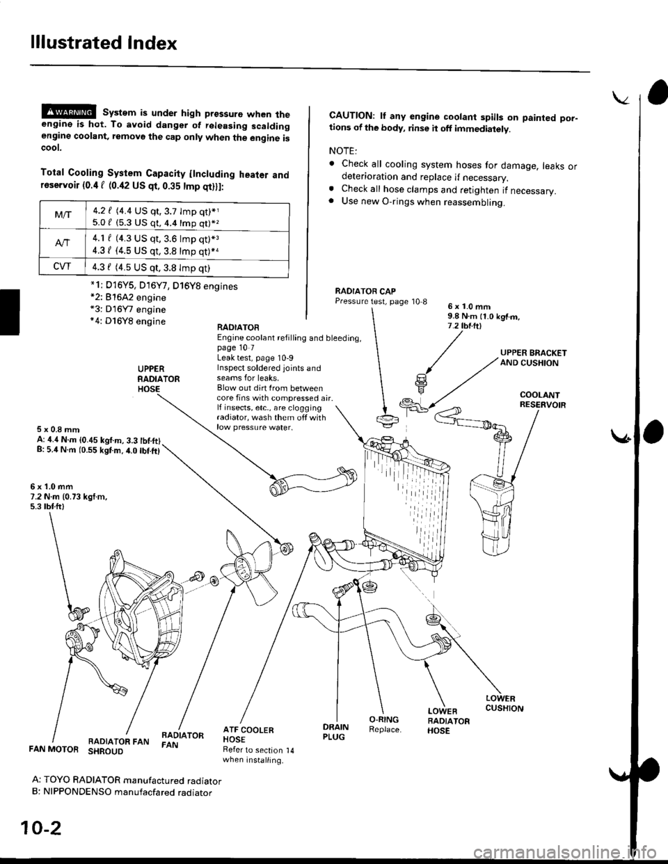
lllustrated Index
@@ system is under high pressure when theengine is hot. To avoid dangsr of rsleasing scaldingengine coolant, removo the cap only when the engine iscoot.
Total Cooling System Capacity flncluding heater andfoservoir (0.4 f (0.42 US qt, 0.35 tmp qt)ll:
*2: 81642 engine*3: D16Y7 engine*4: D16Y8 engine
CAUTION: lf any engine coolant spills on painted por-tions of the body, rinse it off immediately.
NOTE:
. Check all cooling system hoses for damage, leaks ordeterioration and replace if necessary.. Check all hose clamps and retighten if necessary.. Use new O-rings when reassembling.
RADIATOR CAPPressure test, page '10 86x1.0mm9.8 N.m {1.0 kgtm,7.2 tbt.ltl
UPPERRADIATORHOSE
UPPER BRACKETAND CUSHION
COOLANT
RAOIATOREngine coolant refilling and bleeding,page 10 7Leak test, page 10-9Inspect soldered joints andseams for leaks,Blow out dirt Irom betweencore fins with compressed air.lf insects, etc,, are cloggingradiator, wash them off withrow pressure water.
RESERVOIR
5x0.8mmA: ,1.4 N.m {0.45 kgf.m, 3.3 tbtftlg: 5.4 N.m (0.55 kgtm.4.0 tbf.ft)
6x1.0mm7.2 N.m (0.73 kgt.m,5.3 tbtftl
LOWERCUSHION
RADIATOR FANBADIATORFAN
DRAINPLUG
O-RINGReplace.
LOWEBRADIATORHOSE
FAN MOTOR SHROUD
Ar TOYO RADIATOR manufactured radiatorB: NIPPONDENSO manufacfared raoraror
10-2
Refer to section 14when installing.
Mt-|-4.2 f (4.4 US qt,3.7 tmp qt)*j
5.0 / (5.3 U$ q1, 4.4 16p q11*z
4.1 f (4.3 US qt, 3.6 lmp q0*3
4.31 (4.5 US qt, 3.8 tmp qt)*a
CVT4.3 f (4.5 US qt,3.8 Imp qt)
*1i D16Y5, D16Y7, D16Y8 engines
iil
Page 261 of 2189
Radiator
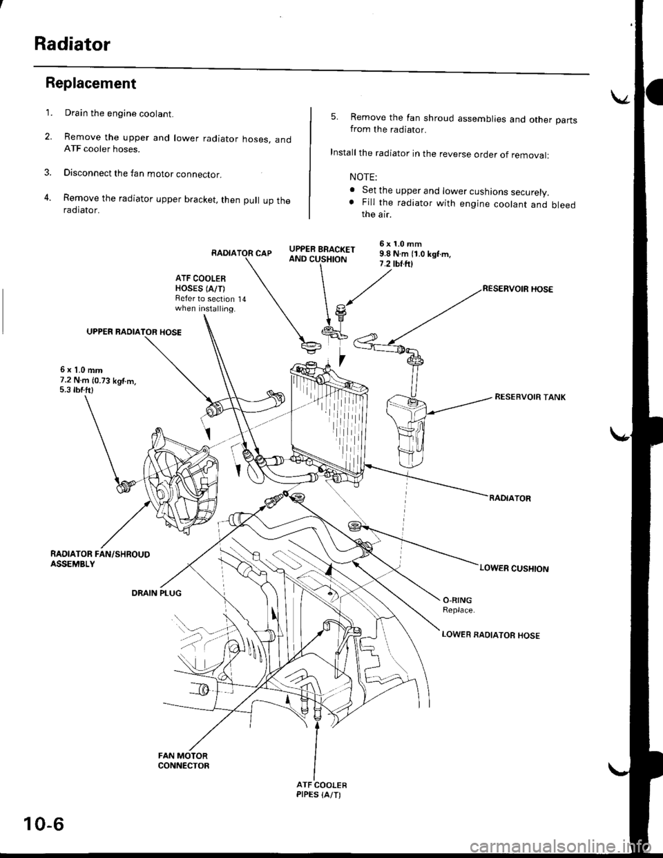
Replacement
Drain the engine coolant.
Remove the upper and lower radiator hoses, andATF cooler hoses.
Disconnect the fan motor connector.
Remove the radiator upper bracket, then pull up theraotator,
RADIA
ATF COOLERHOSES (A/T)Refer to sectionwhen installing.
UPPER RAOIATOR HOSE
6x1.0mm7.2 N.m (0.73 kgf.m.5.3 tbf.ft)
1.
2.
3.
5. Remove the fan shroud assemblies and other partsfrom the radiator.
Install the radiator in the reverse order of removal:
NOTE:
. Set the upper and lower cushions securely.. Fill the radiator with engine coolant and bleedthe air.
6x1.0mmCAPY|lT,PS:|" i.i ru- ii b rgr.-,AND CUSHION7.2 tbr.ftl
14
(
I
RESEBVOIR TANK
RADIATOR
LOWER CUSHION
RAOIATOR FAN/SHROUDASSEMBLY
DRAIN PLUGO-RINGReplace.
LOWER RAOIATOR HOSE
ATF COOLERPIPES {A/T)
,iiiiii
10-6
Page 864 of 2189

Transmission
Installation {cont'd)
Connect the lock-up control solenoid connector. andinstall the transmission ground cable.
6 x '1.0 mm12 N.m {1.2 kgf.m, 8.7 lbl.ft}
LOCK.UP CONTROLSOLENOID CONNECTOR
Connect the staner cables on the staner motor. andinstall the cable holder.
NOTE; When installing the starter cable terminal.make sure that the crimped side of the ring terminalis facing out (see section 23).
6x1.0mm12 N.m 11.2 kg{.m.8.7 tbtftl
{0.9 kg'f.m, 7 lbf.ftl
TRANSMISSIONGROUND CABLE
b
14-186
STARTER CAELE
24. Installthe intake air duct.
D16Y7 engine:
Install the intake air duct and the resonaror.
D16Y8 engine:
lnstall the intake air duct and the air cleaner hous_ang assembly.
25. Refill the transmission with ATF (see page 14_1.18).
26. Connect the positive (+) cable first. then the nega-tive (-) cable to the battery.
27. Check the ignition timing (see section 23).
28. Start the engine. Set the parking brake, and shift thetransmission through all gears. three times. Checkthe shift cable adjustment (see page 14_190).
29, Check the front wheel alignment (see section 1g).
30. Let the engine reach operating temperature (thecooling fan comes on) with the transmission in Nor @ position, then turn it off and check the fluidlevel (see page 14- 7).
31. Road test as described on pages 14-113 thru ,14_116.
Page 1027 of 2189

22. Install the shift cable end on the control lever, and
install the shift cable on the shift cable bracket'
CAUTION: Take care not to bend the shift cable'
23. lnstall the clip in the direction shown.
LOCKNUT
SHIFI CABLE 29 N m {3.0 kg{ m, 22lblftl
SHIFT CABLEERACKET
WASHERIPLASTIC)
CONTROL LEVER
24, Connect the solenoid harness connector. the drive
pulley speed sensor connector. and the ground
cable terminals.
6x1.0mm12 N.m {1.2 kgf.m.8,7 rbtft)
GROUND CABLETERMINAL 6x1.0mm
GROUNDTERMINAL
12 N.m {1.2 kgf'm,8.7lbtfrl
DRIVE PULLEYSPEED SENSORCONNECTOR
SOLENOID HARNESS
CONNECTOR
25. Connect the starter motor cable on the starter motor.
and install the cable holder.
NOTE: When installing the staner motor cable. make
sure that the crimped side of the ring terminal is
facing out (see section 23).
STARTEB
BMOUNTING NUT
9 N.m (0.9 kgf m,7 lbf ft)
26. Install all removed connectors and clamps'
27. Install the distributor.
28. Install the intake air duct and air cleaner housing
29.
assemDly.
Refill the transmission with the recommended
Genuine Honda CVT Fluid (see page 14-2991
CAUTION: While filling the CvT Fluid, bs surs not io
allow dust and other fotoign particles to entor into
the transmission.
Connect the battery positive (+) terminal first, then
the negative (-l terminal to the battery'
Check the ignition timing (see section 23).
Start the engine. Set the parking brake, and shift the
transmission through all gears three times Check
shift cable adjustment (see page 14-355).
Check the front wheel alignment (see section 18)
Let the engine reach operating temperature (the
radiator fan comes on) with the transmission in lXl
or E position, then turn it off and check fluid level'
Perform the start clutch calibration procedure on
page 14-293.
Road test as described on pages 14-296 and 14-297
30.
31.
34.
36.
STARTER MOTOR
14-351
Page 1375 of 2189
Heater
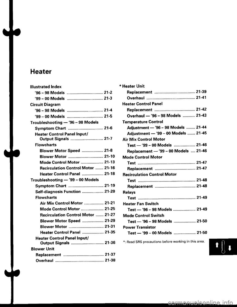
lllustrated Index
'96 - 98 Models ................................ 21'2
'99 - 00 Models ................................ 21'3
Circuit Diagram
'96 - 98 Models .....21-4
'99 - 00 Models ................................ 21-5
Troubleshooting - '96 - 98 Models
Symptom Chart ............................... 21-6
Heater Control Panel Input/
Output Signals ..............,.............. 21-7
Flowcharts
Blower Motor Speed ................... 21-8
Bf ower Motor ,...21'10
Mode Control Motor ............... ,.'.' 21-13
Recirculation control Motor ....... 21-16
Heater Control Panel ................ ... 21 -14
Troubleshooting - '99 - 00 Models
Symptom Chart ............................... 21-19
Seff-diagnosis Function ............,,,.... 21-20
Flowcharts
Air Mix Control Motor ......,.......... 21-21
Mode Control Motor ............... ..... 21 -25
Recirculation Control Motor ....... 21-27
Bf ower Motor Speed .............. .....21'29
Bf ower Motor ....21-31
Heater Control Panel ................,.. 21-35
Heater Control Panel Input/
Output Signals ............................. 21-36
Blower Unit
Repf acement .........21-37
Overhaul ................ 21-38
* Heater Unit
Replacement ....'....21-39
overhaul """" """' 21-4'l
Heater Control Panel
Repfacement .........21'42
Overhaul -'96 - 98 Models ........... 21-43
Temperature Control
Adjustment - '96 - 98 Models """" 21-44
Adiustment - '99 - 00 Models .......21-45
Air Mix Control Motor
Test - '99 - 00 Models ...........' .......21'46
Replacement - '99 - 00 Models ....21'46
Mode Control Motol
Test ................, .,...'.21'47
Replacement '.'."...21-47
Recirculation Control Motor
Test ................. .......21-48
Repf acement ......." 21-48
Relays
Test ................. .......2'l-49
Heater Fan Switch
Test - '96 - 98 Models ............. .......21-49
Mode Control Switch
Test -'96 - 98 Models ..........."....... 21-50
Power Transistor
Test - '99 - 00 Models ....'........ ....".21-50
*: Read SRS Drecautions before working in this area.
Page 1376 of 2189
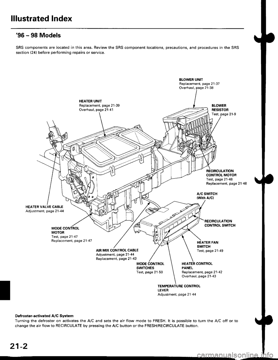
lllustrated Index
'96 - 98 Models
SRS components are located in this area. Review the SRS component locations, precautions, and procedures in the SRS
section {24) before performing repairs or service.
BLOWER UNITReplacement, page 21-37Overhaul, page 21-38
HEATER UNITBeplacement, page 21-39Overhaul, page 21-41BLOWERRESISTOBTest,
CONTROL MOTORTest, page 21-48Replacement, page 21'48
a/c swtTcH{wirh A/c)
MOO€MOTORTest, page 21 47Replacement, page 21'47
AIR MIX CONTROL CABLEAdjustment, page 2'1-44Replacement, page 21'43
HEATER FANswtTcHTest, page 2l'49
MODEHEATER CONTBOLPANELswrTcHEsTest, page 21 50Rgplacement, page 2'l-42Overhaul, page 21-43
TEMPERATURE CONTROLLEVERAdiustment, page 21 44
Detroster-aqtivated A/C System
Turning the defroster on activates the A,/C and sets the air flow mode to FRESH. lt is possible to turn the A,/C off or to
change the air flow to RECIRCULATE by pressing the A/C bunon or the FRESH/RECIRCULATE button.
21-2
Page 1377 of 2189
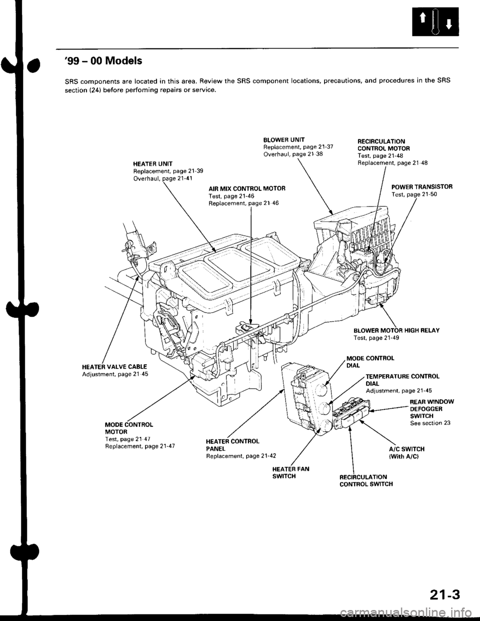
'99 - 00 Models
SRS components are located in this area, Review the SRS component locations, precautions, and procedures in the SRS
section (24) betore perfoming repairs or service.
HEATER UNITReplacement, page 21'39
Overhaul, page 21-41
BLOWEB UNITReplacement, page 21-37Overhaul, page 21 38
HEATER FANswtTcH
RECIRCULATIONCONTROL MOTORTest, page 21-48Beplacement, page 21-48
AIR MIX CONTROL MOTOBTest, page 21-46Replacement, page 21 46
BLOWERTest, page 21-49
POWER TRANSISTORTest, page 21 50
HIGH RELAY
MODE CONTROLDIALHEATER VALVE CABLEAdjustment, page 21 45TEMPERATURE CONTROLDIALAdjustment, page 21-45
REAR WINDOWDEFOGGERswtrcHSee section 23MODEMOTORTest, page 21 47Replacement, page 2 l-47A/C SWTTCH
lwith A/cl
CONTROL SWITCH
21-3