Page 1230 of 2189
l}tWheel Sensor Replacement
NOTE:
. Becareful when installingthe sensors to avoid twisting the wires.
. The torque value of the bolts is 9.8 N.m (1.0 kgf.m, 7 lbf.ft).
Front
FRONT WHEEL SENSOR
Rear
1. Remove the hub bearing unit (see section 18).
2. Remove the four backing plate bolts.
3, Pull the backing plate away from the trailing arm, then remove the wheel sensor. lt is not necessary to disconnect the
brake line.
NOTE: This illustration is drum brake type. The torque value of the disk type is same as drum type.
REAR WHEEL SENSOR
J\
It
19-77
Page 1349 of 2189
Sub-frame
Sub-frame Torque Sequence:
CAUTION: After loos€ning the sub-frame mounting bolts, be sure to replace them with new ones.
BOLTS
10 x 1.25 mm38Nm{3.9kg{.m:
14 x 1.5 mm90 N m (9.1 ks{ m,66 rbf.ft)Replace.
28 tbf.ft)
20-119
Page 1425 of 2189
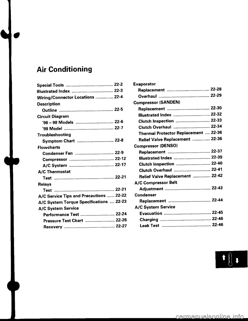
Air Conditioning
Speciaf Tools ......'.....' 22-2
f f f ustrated f ndex ......................... ".......' 22-3
Wiring/Connector Locations'.........'.... 22'4
Description
Outfine ............ .......22-s
Circuit Diagram
'96 - 98 Models ......"..........".......'.... 22-6
'99 Modef """""""' 22-7
Troubleshooting
Symptom Chart ".'......""................. 22-8
Flowcharts
Condenser Fan .........".................,..'. 22-9
Compressor .....""" 22-12
A/C System .........'.22'17
A/C Thermostat
Test ........'.......' """'22'21
Relays
Test ....."'......... ..""'22-21
A/C Service Tips and Precautions ......22-22
A/C System Torque Specifications '...22-23
A/C System Service
Performance Test ... '."......... ".... ....'..22-24
Pressure Test Chart .................. .... "' 22-26
Recovery ...".........," 22-27
Evaporator
Replacement .....",' 22'24
Overhauf .....-.....""' 22'29
Compressor {SANDEN}
Repf acement ......'.' 22-30
fffustrated fndex ......"..................'.... 22'32
Cf utch Inspection ......... "............ ...... 22-33
Clutch Overhau I ........................ ....... 22-34
Thermal Protector Replacement .... 22-36
Relief Valve Replacement ......'..."". 22-36
Compressor (DENSO)
Repfacement ..""',' 22-37
lf lustrated Index ............................... 22-39
Clutch lnspection ............."'...... "'.... 22-40
Cf utch Overhaul .....................'......... 22-41
Ref ief Valve Replacement'..'......"'.. 22-42
A/C Compressor Belt
Adiustment ............22'43
Condenser
Repfacement .......,,22'44
A/C System Service
Evacuation ...,,,.......22-45
Charging '..........--'..22'46
Leak rest """""""'22-46
Page 1447 of 2189
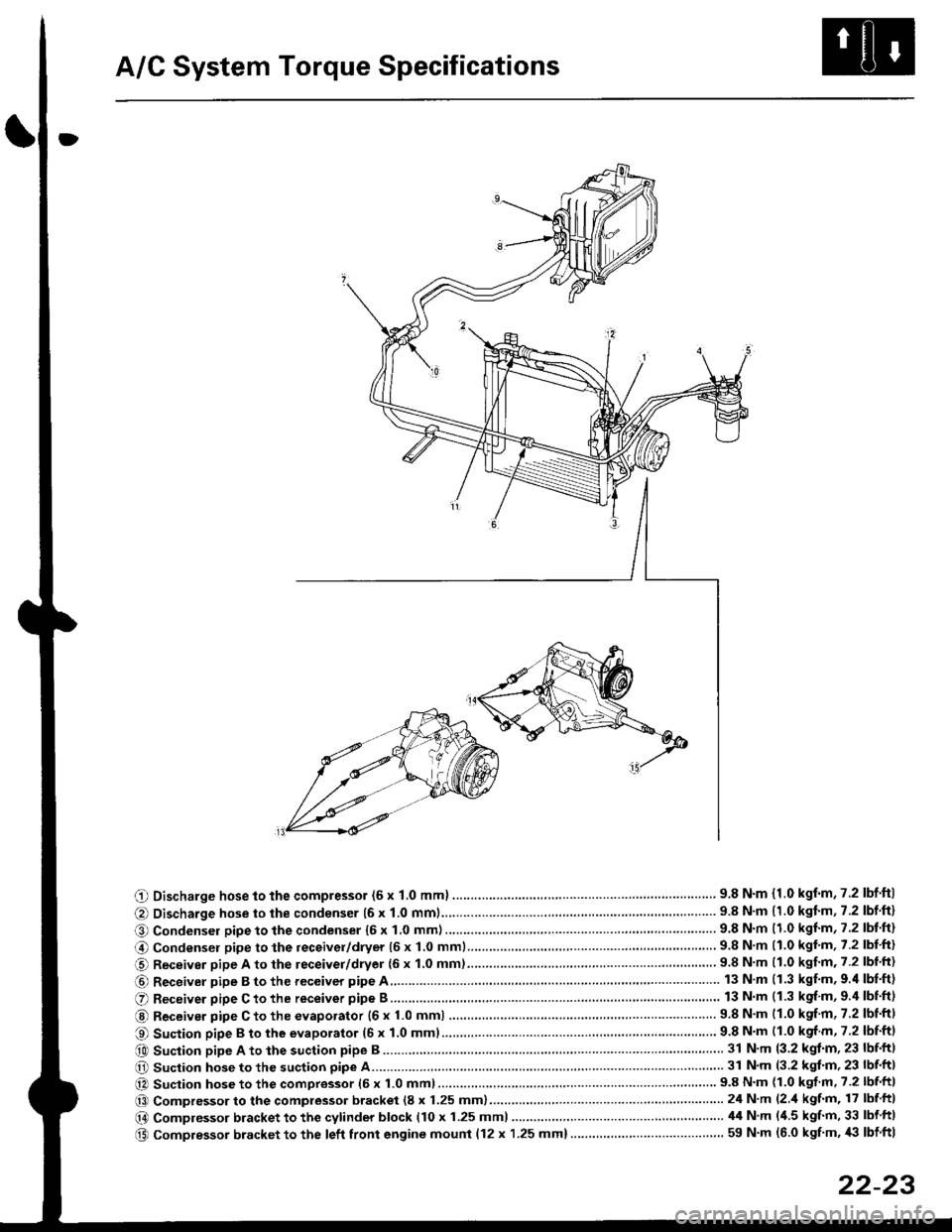
A/C System Torque Specifications
O Discharge hose to the compressor (6 x 1.0 mml ............... .. .... ...............' 9.8 N'm {1.0 kgf'm,7.2 lbf'ftl
@ Discharge hose to the condenser {6 x 1.0 mm1................... '... ...... . ......... 9.8 N'm 11.0 kgf'm, 7.2 lbf'ft}
O Condenser pipe to the condenser 16 x 1,0 mm)...............'. . . . ...........'..... 9.8 N'm (1.0 kgl'm, 7.2 lbt'ft)
@ Condensel pipe to the receivel/dryer (5 x 1.0 mml......... ..... . ... . '.......... 9.8 N'm (1.0 kgl'm, 7.2 lbt'ft)
O Receiver pipe A to the leceiver/dryer {6 x 1.0 mm)......... ... .......... .. . . .... 9.8 N'm 11.0 kgf'm. 7.2 lbl'ft)
@ Receiver pipe B to the receiver pipe A 13 N m (1.3 kgf'm, 9.'l lbf'ft)
O Receiver pipe C to the receiver pipe B 13 N m (1.3 kgf'm, 9.4 lbnftl
@ Receiver pipe C to the evaporator {6 x 1.0 mm) ....... 9.8 N'm (1.0 kgf'm, 7.2 lbtftl
O Suction pipe B to the evaporator (6 x 1.0 mml................ . .........'......'....... 9.8 N'm (1.0 kgf m, 7.2 lbf'ftl
e0 Suction pipe A to the suction pipe B ...'. . ...... . ... ...... 31 N'm (3.2 kgt'm, 23 lbf'ftl
O Suction hose to the suction pipe A... ............ . . '......... 31 N'm (3.2 kgl'm, 23 lbf'ft|
@ Suction hose to the compressor (6 x 1.0 mm)................... .. . ... .. ............ 9.8 N'm (1.0 kgf'm' 7.2 lbf'ft|
@@ Compressor to the compressor bracket (8 x 1.25 mm)... ..-........'.'......-.......24 N'm (2 'l kgf'm, 17 lbf ftl
@ Compressor bracket to the cytinder block (10 x 1.25 mml 44 N'm l'1.5 kgf'm, 33 lbf ftl
@ Compressor bracket to the left front engine mounl {12 x 1.25 mm}..... . . . . .. ................. ... ... 59 N'm (6.0 kgf'm, '|i} lbf ftl
22-23
Page 1566 of 2189
Starting System
Starter Test lcont'dl
Ch€ck tor Wear and Damage
The starter should crank the engine smoothly and
steadily, lf the starter engages. but cranks the engine
erratically, remove it, and inspect the starter drive gear
and torque converter or flywheel ring gear for damage.
. Check the drive gear overrunning clutch for binding
or slipping when the armature is rotated with the
drive gear held,- lf damaged. replace the gears.
Check Cranking Voltsge and Curr€nt Draw
Cranking voltage should be no less than 8.5 volts.
Current draw should be no more than 350 amperes.
lf cranking voltage is too low, or current draw too high,
check for;
. dead or low batterv.
. open circuit in starter armature commutator seg-
ments,
. starter armature dragging.
. shorted armature winding.
o excessive drag in engine.
Check Cranking rpm
Engine speed during cranking should be above 100 rpm,
lf speed is too low, check for:
. loose battery or stanerterminals.
. excessively worn starter brushes,
. open circuit in commutator segments.
o dirty or damaged helical spline or drive gear.
. defective drive gear overrunning clutch.
Check Siarter Disengag€ment
With the shift lever in El or @ position (A/T) or with the
clutch pedal depressed (M/T), turn the ignition switch to
START (lll), and release to ON (ll).
The starter drive gear should disengage from the torque
converter or flywheel ring gear when you release the
Key.
lf the drive gear hangs up on the torque converter or fly-
wheel ring gear, check for:
. solenoid plunger and switch malfunction,
. dirty drive gear assembly or damaged overrunning
clutch.
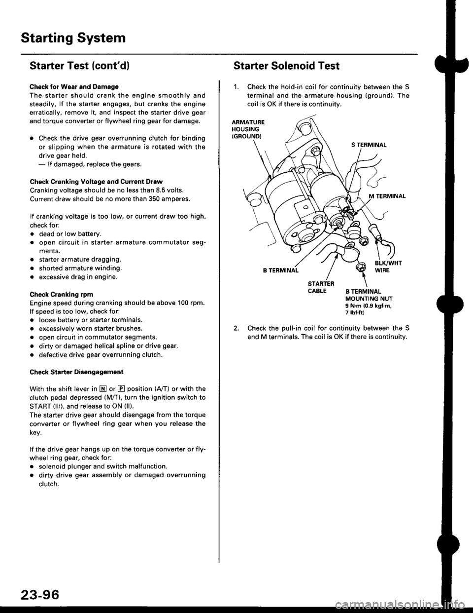
Starter Solenoid Test
1. Check the hold-in coil for continuitv between the S
terminal and the armature housing (ground). The
coil is OK if there is continuitv,
ARMATUREHOUSING(GROUND)
S TERMINAL
M TERMINAL
B TERMINAL
STARTERCAELE B TERMINALMOUNTING NUTI N.m {0.9 kgf.m,7 tbf.ft)
Check the pull-in coil for continuity between the S
and M terminals. The coil is OK if there is continuity.
Page 1581 of 2189
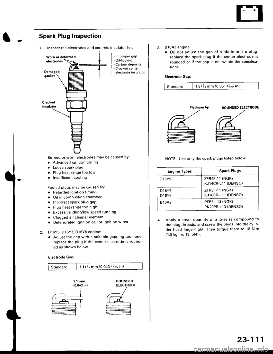
1. Inspect the electrodes and ceramic insulator for:
Spark Plug lnspection
Crackedinsulator
2.
[ . t.p,op", grp
| . Oil-fouling
i . Carbon deposits
| . Cracked center
I electrode insulator
Burned or worn electrodes may be causecl by:
. Advanced ignition timing
. Loose spark plug
. Plug heat range too low
. Insufficient cooling
Fouled plugs may be caused bY:
. Retarded ignition timang
. Oil in combustion chamber
. Incorrect spark plug gap
. Plug heat rangetoo high
. Excessive idling/low speed running
. Clogged air cleaner element
. Deteriorated ignition coil or ignition wares
D16Y5, D16Y7, D'16Y8 enginel
. Adjust the gap with a suitable gapping tool, and
replace the plug il the center electrode is round-
ed as shown below.
Electrode Gap:
1.1 mm
{o.{X:l in)ROUNDEDELECTRODE
Standard 1.1r8 ' mm (0.043i800oin)
Worn or detormed
1T
23-111
3. 816A2 engine:
. Do not adjust the gap of a platinum tip plug;
replace the spark plug il the center electrode is
rounded or it the gap is not within the specifica
tro ns.
Electlode Gap:
Standard 1.3181mm (0.051 !3oo" in)
flOUNDED ELECTROOE
',/
@_
:
Platinum tip
NOTE: Use only the spark plugs listed below
4. Apply a small quantity of anti seize compound to
the plug threads, and screw the plugs into the cylin
der head finger-tight. Then torque them to 18 N m
11.8 kgf.m, 13lbnft).
Engine TypesSpark Plugs
D16Y5ZFR4F 11 (NGK)
KJ14CR-111 (DENSOi
D16Y7,
D,I6Y8
ZFRSF-11 (NGK)
KJ16CR-111(DENSO)
81642PFR6L.13 (NGK)
PK2OPR.L13 (DENSO}
Page 1595 of 2189
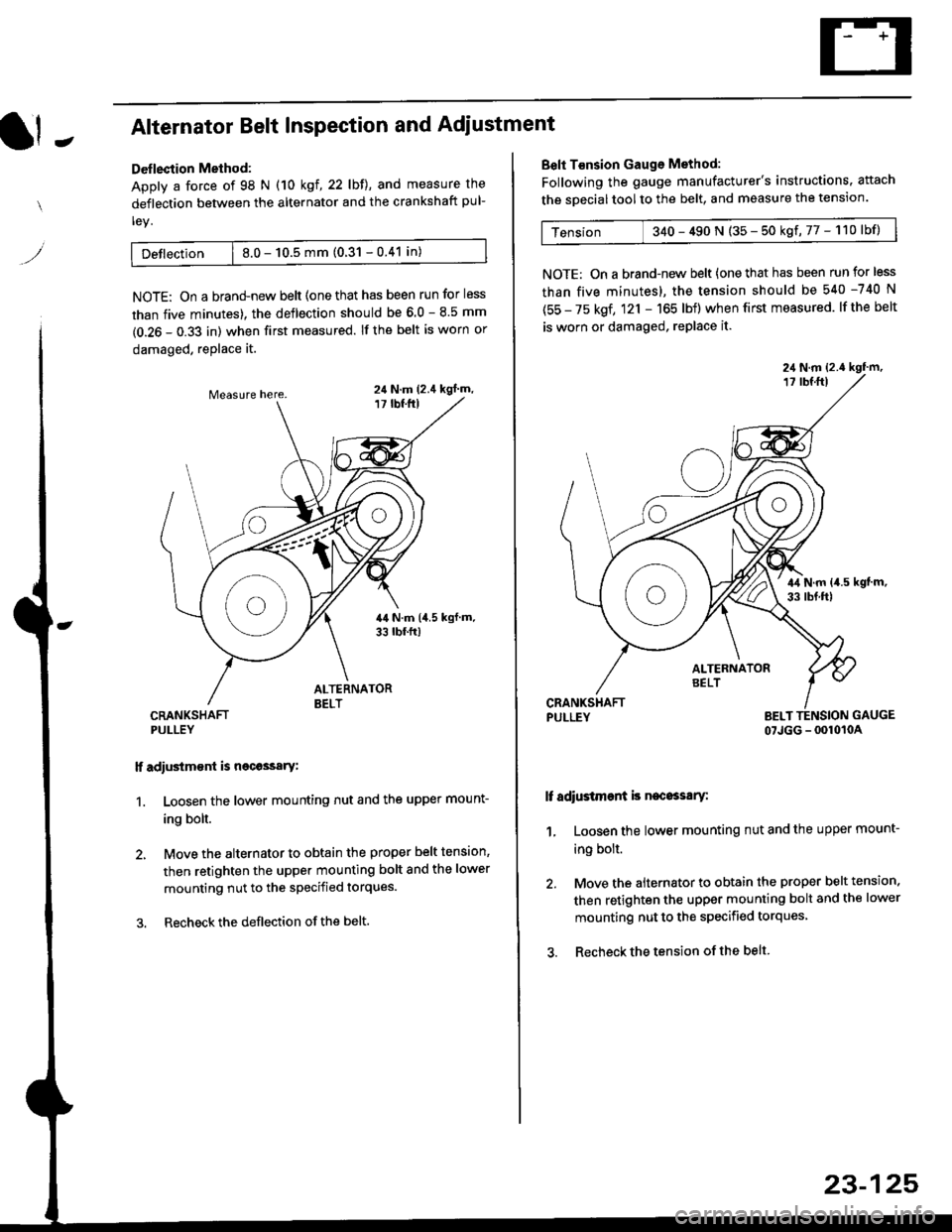
It -Alternator Belt Inspection and Adiustment
Deflection Method:
Apply a force of 98 N (10 kgl,22lbll, and measure the
deflection between the alternator and the crankshaft pul-
ley.
Detlection | 8.0 - 10.5 mm (0.31 - 0.41 in)
NOTE: On a brand-new belt {one that has been run for less
than five minutes). the deflection should be 6.0 - 8.5 mm
(0.26 - 0.33 in) when first measured. If the belt is worn or
damaged, replace it.
CRANKSHAFTPULLEY
lf adiustm€nt is necossary:
1. Loosen the lower mounting nut and the upper mount-
ing bolt.
2, Move the alternator to obtain the proper belt tension,
then retighten the upper mounting bolt and the lower
mounting nut to the specified torques.
3. Recheckthe deflection ofthe belt.
24 N.m (2.4 kgl m,
Belt T€nsion Gauge Method:
Following the gauge manufacturer's instructions. attach
the soecial tool to the belt, and measure the tension.
Tension 340 - 490 N (35 - 50 kgf,77 - 110lbf)
NOTE: On a brand-new belt {one that has been run for less
than five minutes), the tension should be 540 -740 N
(55 - 75 kgf, 121 - 165 lbf) when first measured. lf the belt
is worn or damaged, replace it.
PULLEY BELT TENSION GAUGE
07JGG - 0010104
It adiustment is necossary:
1, Loosen the lower mounting nut and the upper mount-
ing bolt.
2. Move the alternator to obtain the proper belt tension.
then retighten the upper mounting bolt and the lower
mounting nut to the specified torques
3. Recheck the tension of the belt
23-125