Page 928 of 2189

Troub|eshootingF|owchart_PH-PLControJLinearSo|enoid
NOTE| Record all treeze data before you troubleshoot
Possible cause
' Disconnected solenoid harness
connectof. Short or oPen in PH_PL control
linear solenoid wire. Faulty PH-PL control linear sole_
noidSOLENOIO HARNESS8P CONNECTOR
GRN/WHT
Terminal side of male termlnals
Wire side ol female terminals
. OBD ll Scan Tool indicates Codo
P1873.. sef-diagnosis E indicalor light
indicat6 Code 31.
Measure PH-PL Control Linear
Solenoid Resistance at the Sole_
noid Hatness Connectot:1. Disconnect the 8P connector
from the solenoid harness con-
nector,2. Measure the resistance
between the No 2 and the No.
6 terminals ofthe solenoid har
ness connector'
ls the resistance 3.8 - 6.8 0?
Check PH-PL Control Lineer
Solenoid for a Short Circuit:
1. Disconnect the A 126P) con-
nector lrom the TCM
2. Check for continuity between
body ground and the A2 ter
minal and the A15 terminal
individually.
Repair short in th€ wires
between the A2 and A15 lermi_
nals and the body glound.
Measute PH-PL Control Linear
Solenoid Resi3tance:1. Connect the 8P connector to
the solenoid harness connec-
tor,2, Meas u re the reslslance
between the ,q2 and A15 ter_
Rep.il loose tetminal or oPen in
th6 wires betwccn the A2 and
A15 lerminals and the solenoid
harness conn€ctol.
lsthe resistance 3.8-6 8 O?
Check for loose TCM connactors
lf neceasery, Substitute a known-good TCM and rechock.
PNK/BLK
TCM CONNECTOR A (26P)
oPNK/BLK
I234578I10l11213
11't5161720/,,/232526
IGRN/wHr
o
*r}l
t'T,
E[
PNK/8LK
3a5I910111213
1620232526
GRN/WHT
14-251
Page 940 of 2189
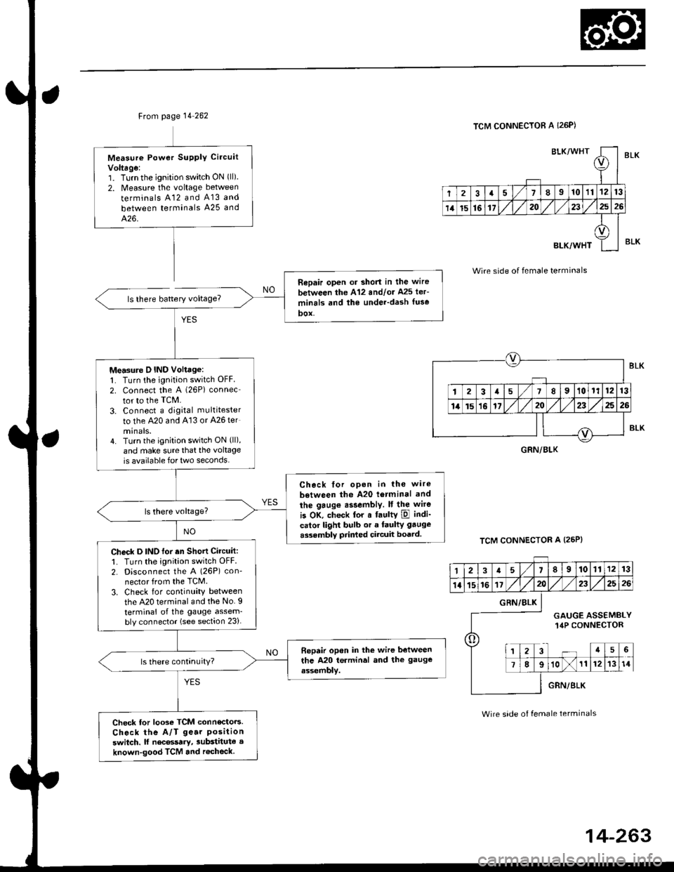
Ftom page 14 262
ls there battery voltage?
Measure Powet SUPPIY Ci.cuit
Voltage:1. Turnthe ignition switch ON (ll)
2. Measure the voltage between
terminals A12 and A13 and
between terminals A25 and
426.
Repair open or short in the wire
between the A'12 andlor Ms ler-
minrls and the under-dash fuse
DOX,
Measure D IND Voltage:1. Turn the ignition switch OFF
2. connect the A (26P) connec
tor to the TcM.
3. Connect a digkal multitester
to the A20 and A'13 or A26 ter
minals.4. Turn the ignition switch ON (ll),
and make sure that the voltage
is available for two seconds.
Check tor opon in the wire
between the A20 l6rminal and
the gaug€ assembly. It the wite
is OK, check tor a faultY ipl indi-
calor light bulb or a faulty gauge
assembly prir ed circuit boatd.
Check D INO for an Shott Circuit:1. Turn the ignition switch OFF
2. Disconnect the A (26P) con-
nector from the TCM.
3. Check for continuity between
the A20 terminal and the No. I
terminal of the gauge assem-bly connector (see section 23).
Bepair open in the wire between
the A20 terminal and the gauge
assembly.
Check tor looso TCM connecto.s.
Check the A/T ge.r Positionswitch. lf nec6ssary, substitute a
known-good TCM and r€check
BLK/WHTI
r
2a710111213
14t5161720232526
BLK/WHT
A
II
TCM CONNECTOR A I26P)
Wire side of female terminals
TCM CONNECTOR A (25P}
BLK
BLK
GRN/BLK
12a58910111213
1l15161720232526
o
GRN/BLK
GAUGE ASSEMBLY14P CONNECTOR
a5
78910111214
GRN/BLK
Wire side of female terminals
Page 949 of 2189
ElectricalTroubleshooting ('99 - 00 Models)
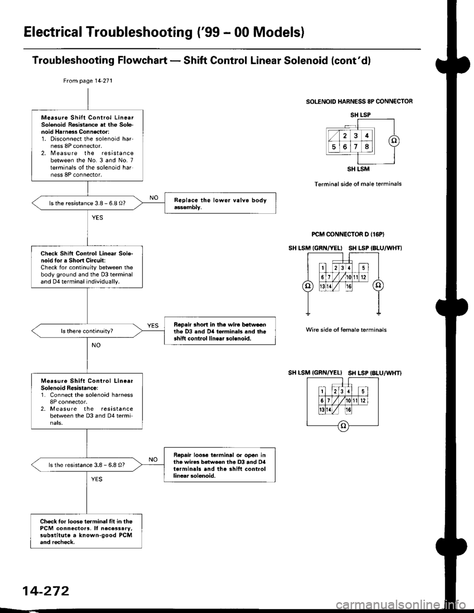
Troubleshooting Flowchart - Shift Gontrol Linear Solenoid (cont'dl
SOI."ENOID HARNESS 8P CONNECTOR
Terminal side of male terminals
PCM CONNECTOR D {16P}
SH LSM IGRN/YELI SH LSP {BLU/WHTI
Wire side oI temale terminals
SH LSM {GRN/YELI SH LSP IALU/WHT}
tuom page 14 271
Measure Shift Control LinearSolenoid R6sistance at the Sole-noid Hrrness Connector:1. Disconnect the solenoid harness 8P connector.2. Measure the resistancebetween the No. 3 and No- 7terminals oI the solenoid harness 8P connector,
ls the resistance 3.8 - 6.8 o?
Check Shift Control Lin€ar Sole-noid tor a Short Circuit:Check for continuity between thebody ground and the D3 terminaland D4 terminal individually.
Rep.ir short in th€ wir€ tr€twlrenihe D3 and D4 torminab .nd theshift cont.ol line.. solenoid.
Measure Shitt Conirol LineerSolenoid Resbtance:1. Connect the solenoid harness8P connector.2. Measure the resistancebetween the D3 and D4 termi-nats.
Repeir loose ierminrl or open inthe wire3 between tho D3 and D4terminals end the shift controllinear solenoid.
ls the resistance 3.8 - 6.8 O?
Check tor loose terminal fit in thePCM connector3, It necessary,substitute a known-good PCMand recheck.
SH LSP
SH LSM
14-272
Page 951 of 2189
Electrical Troubleshooting ('99 - 00 Models)
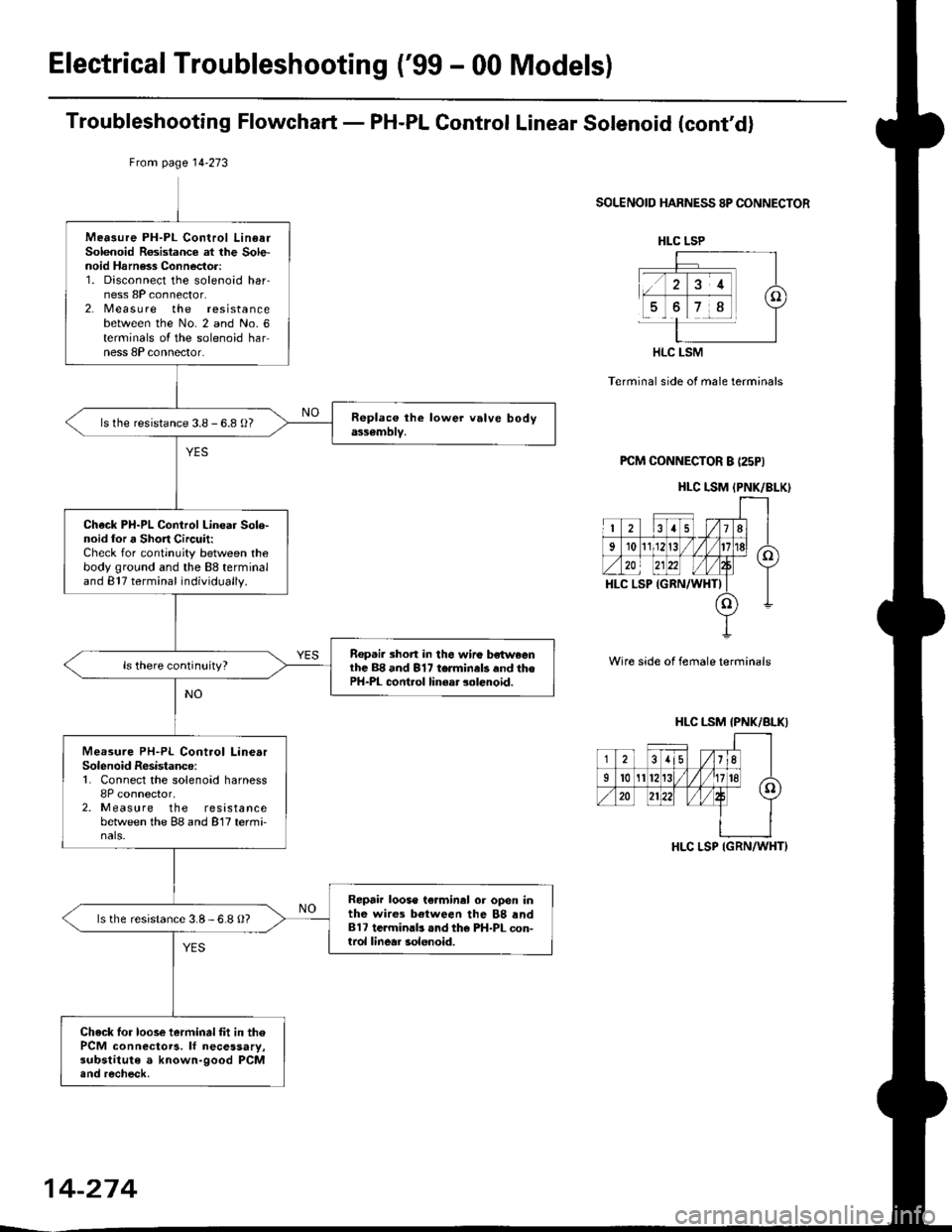
Troubleshooting Flowchart - PH-PL Gontrol Linear Solenoid (cont'd)
From page l4-273
SOLENOID HARNESS 8P CONNECTOR
Terminal side of male terminals
PCM CONNECTOR B (25PI
Wire side of female terminals
Mea3ure PH-PL Control LinearSolenoid Rosistance at lhe Sole-noid Harness Connector:1. Disconnect the solenoid har-ness 8P connector.2. Measu re the resistancebetween the No. 2 and No. 6terminals oI the solenoid harness 8P connector.
ls the resistance 3.8 - 6.8 O?
Check PH-PL Control Linear Sole-noid lor a Short Circuit:Check for continuity between thebody ground and the 88 terminaland 817 terminal individually.
Rep.i. 3hort in the wiro bsh^,eenlhc 88 and 817 terminals and thePH-PL cont.ol linear solenoid.
Measure PH-PL Control LinearSolenoid Resistance:1. Connect the solenoid harness8P connector,2. Measure the resistancebetween the 88 and 817 termi-nals.
Repair loose te.minal or open inthe wires between the 88 rnd817 te.minlb .nd the PH-PL con-trol linear solenoid.
ls the resistance 3.8-6.8 O?
Check lor loose ierminal fit in thePCM connectoTa. lf necessary,substitute a known-good PCM.nd recheck.
HLC LSP
HLC LSM
HLC I.SM (PNK/BLK)
HLC LSM {PNK/BLKI
-j-i8lisli.((
35/11
Il0A/'.n20
HLC LSP IGRN/WHT}
14-274
Page 1205 of 2189
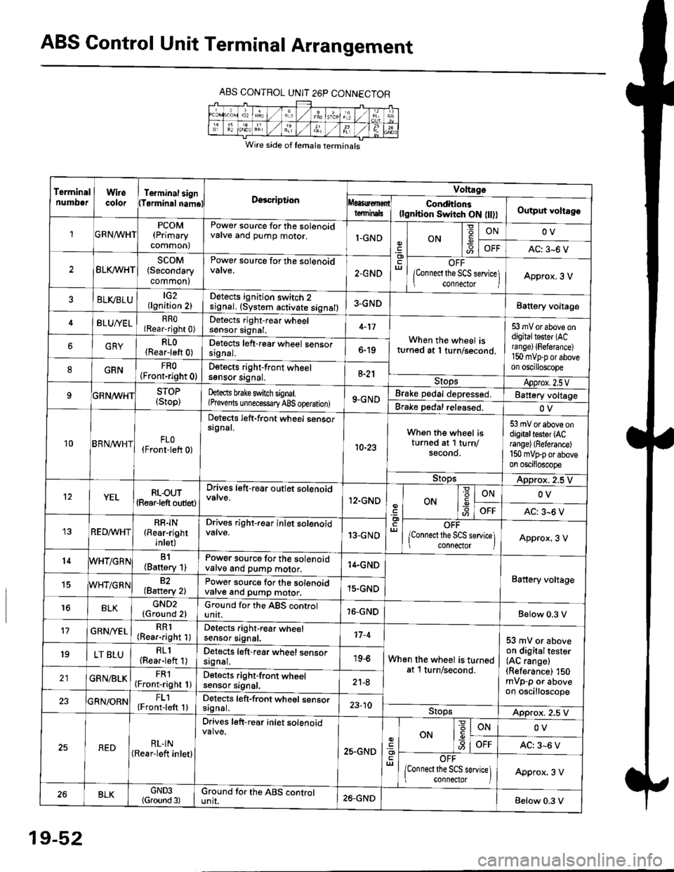
ABS Control Unit Terminal Arrangement
ABS CONTROL UNIT 26P CONNECTOR
Wire side of temale terminals
Terminalnumo0rWirecolorTerminal signTerminalnamoDgscriptionVoltage
Conditions(lgnition Switch ON flt))Output voltagoteminals
PCOM(Primary
common)
Power source for the solenoidvalve and pump motor.1-GNDON
=ONOV
AC: 3-6 V
BLK/WHTscoM(Secondary
common)
Power source for the solenoid
2.GNDOFF
lConnect the SCS service\
conneclor lApprox. 3 V
ELVBLUtG2(lgnition 2)Detects ignition switch 2
!9nal. (system activate signal)3-GNDBatt€ry voltage
BLU/YELRRO(Rear-right 0)Detects right-rear wheelsensor signal.4-17
When the wheel isturned at 1 turn/second.
53 mV or above ondigitaltester (ACra nge) {Fefera nce)150 mvp-p or aboveon oscilloscope
6GRYRLO(Rear-left 0)Detects left-rear wheel sensorsrgnal.6-19
8GRNFRO(Front-right 0)D€tects right-front wheelsgnsor srgnal,a-21StopsApprox.2.5VSTOP(Stop)hects brake switch signal.(Prevents unnecess€ry ABS operation)9-GNDBrake pedal depressed.Battery voltage
Brake pedal released.OV
10BRN^/vHTFLO(Front-left 0)
Detects left-front wheel sensorsignal.
10-23
When the wheel isturned at 1 turn/secono.
53 mV or above ondigitaltester (ACrange) (Referance)
150 mVFporaboveon oscilloscope
9!opsApprox. 2.5 V
12YELRLOUT(Rearjeft outlet)
Drives left-rear outlet solenoid
12.GNDON-9ONOV
OFFAC: 3^6 V
REDMHTRR]N(Rear-right
inlet)
Drives right-rear inlet solenoidvalve.13-GNDOFF
lconnect the SCS service]i connector IApprox. 3 V
14B1(Battery 1)Power source for the solenoidvatve and pump motor.14.GND
Battery voltage15WHT/G R N82(Baftery 2)Power source for the solenoidvarve ano pump motor.15.GND
r6BLKGND2{Ground 2)Ground for the ABS controlunit.16-GNDBelow 0.3 V
17GRN/'/ELRR1(Rear-right 1)Detects right-rear wheelsensor signal.17-4
When the wheel is turnedat 1 turn/second.
53 mV or aboveon digitaltester(AC range)(Referance) 150mVp-p or aboveon oscilloscope
19LT BLURLl(Rea.-left 1)Detects left-rear wheel sensorsagnal.19-6
GRN/BLKFRl(Front-right 1)Detects right-front wheelsensor signal.21-8
FL1(Front-left 1)Detects left-front wheel sensorsignal.23-10StopsApprox. 2.5 V
REDRL-IN(Rear-lett inletl
Drives left-r€ar inlet solenoid
25.GND
ut
ON
'6
-9ONOV
OFFAC: 3-6 V
OFF
lconnect the SCS service] connector lApprox. 3 V
BLKGND3(Ground 3)Ground for the ABS cgntrolunit.26.GNDBelow 0.3 V
19-52
Page 1215 of 2189
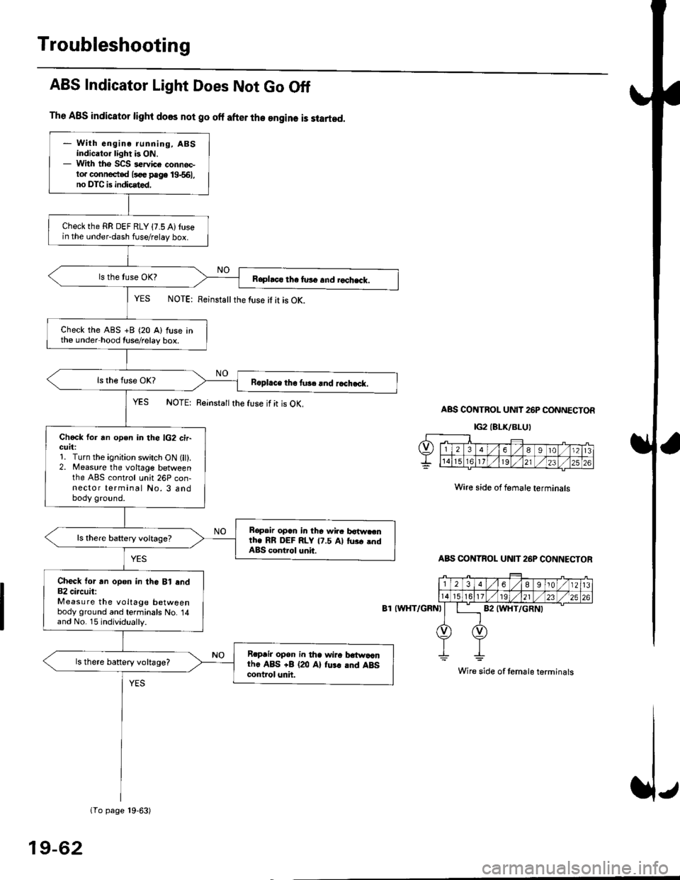
Troubleshooting
The ABS indicator light does not go off after the engine is started.
- With engine running, ABSindicator light is ON.- With tho SCS sewice connec-to. connected l3oe page 19-561,no DTC is indicated,
Checkthe RR DEF RLY {7.5 A)tusein the under-dash fuse/relay box.
Raphco tha furo and rochack.
Check the ABS +B (20 A) fuse inthe under hood tuse/relay box.
R6pl.ce tho tu3c lnd r.ch.ck.
Chock for an open in the lG2 cir-GUrt:1. Turn the ignition switch ON (lt).2. Measure the voltage betweenthe ABS control unh 26P con-nector terminal No. 3 andbody ground.
Bopair opcn in tha wir. botw.cnth. RR DEF RLY 17.5 Al tus. .ndABS control unit.
Check tor an opon in thG Bl end82 circuit:Measure the voltage betweenbody ground and terminals No. 14and No. 15 individually.
Rrpair opsn in tha wiro t atwa,anthe ABS +B (20 Al fu.r .nd ABScontrol unh.
ls there banery voltage?
1To page 19-63)
ABS Indicator Light Does Not Go Off
YES NOTE: Feinstattthe luse it it is OK.
YES NOTE: Reinsta
the fuse if it is OK.ABS CONTROL UNIT 26P CONNECTOR
IG2IELK/BLUI
Wire side of female terminals
ABS CONTBOL UN]T 26P CONNECTOR
8T IWHT/GRNI
Wire side of temale terminals
19-62
Page 1224 of 2189
tfMain Relay
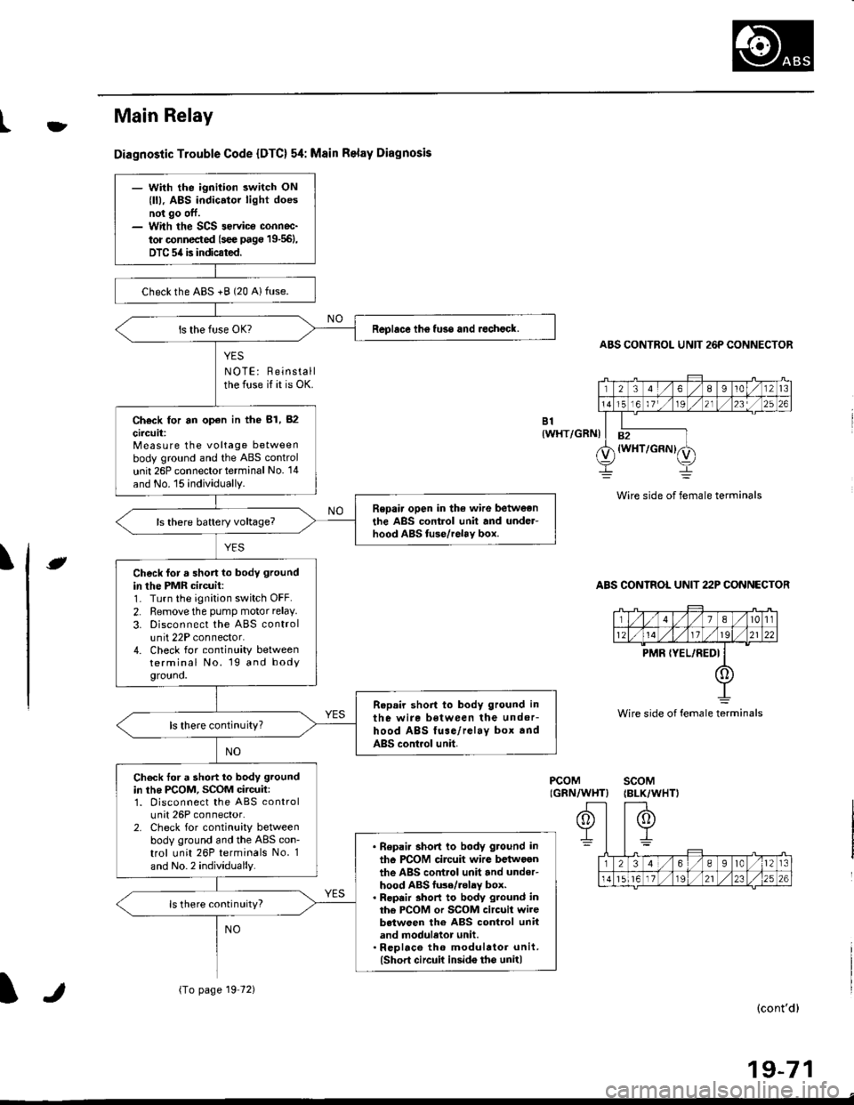
Diagnostic Trouble Code {DTC} 54: Msin Relay Diagnosis
YES
NOTE: Reinstallthe fuse if it is OK.
ABS CONTROL UNIT 26P CONNECTOR
Wire side of female terminals
ABS CONTROL UNIT 22P CONNECTOR
B1{WHT/GRNI
\e
PCOMIGRN/WHT}scoM{BLK/WHTI
(cont'd)
19-71
Wire side of female terminals
- With the ignition switch ON
{ll), ABS indic.tor light doesnot go off.- With the SCS 3ervica connoc-
tor connected (s€e pag€ 19-561,
DTC 54 is indicated.
checkthe ABS +B (20 Alfuse.
Replace th6 fuso and rechock.
Ch€ck for an op€n in the 81, 82
circuit:Measure the voltage betweenbody ground and the ABS control
unit 26P connector terminal No. '14
and No. 15 individually.
Repair open in the wire betweonthe ABS control unit and under-hood ABS tuse/relav box.
Check for a short lo body ground
in the PMR circuit:1- Turn the ignition switch OFF.
2. Remove the pump motor relay.
3. Disconnect the ABS controlunit 22P connector.4. Check for continuity betweenterminal No. 19 and bodygrouno.
Repair short to body ground in
the wire between the undor-hood ABS fuse/relay box andABS control unit.
ls there continuity?
Check tor a short to body ground
in the PCOM, SCOM circuit:1. Disconnect the ABS controlunit 26P connector.2. Check for continuity betweenbody ground and the ABS con-trol unit 26P terminals No. 1
and No.2 individually.
. Bepai. short to body ground in
tho PCOM circuit wire betwoenthe ABS control unit and under-hood ABS fu3e/.olay box.. Repair 3hort to body ground inthe PCOM or SCOM circuit wirebetween the ABS control unitand moduletor unit.. Rcplace th6 modulator unit.(Short circuit insido tho unit)
ls there continuity?
{To page 19 72)lr
Page 1225 of 2189
Troubleshooting
Main Relay (cont'd)
(From page 19'71)
PCOM(GRN/WHTIscoM(BLK/WHT}Check tor a short to powor in thePCOM, SCOM circuit:1. Turn the ignition switch ON r).2. Measure the voltage betweenbody ground and ABS controlunit 26P connector terminalsNo. l and No.2 individually.
. Repair 3hoit to power in ihercOM circuil wire bgtween theABS control unit end unde.-hood ABS fuse/relay box.. Repair sho to powor in thaPCOM oJ SCOM circuit wirobetwoen the ABS control unitand modulator unit.' Repl.co the modul.tor unit.lshort to Dowcr iGido the unit)Replace the ABS control unit.
Vo lta ge
19-72