Page 417 of 2189

PGM-FI System
Primary Heated Oxygen Sensor (Primary HO2SI (sensor l)
(Dl6Y5 engine with M/T) (cont'd)
(From page 1l-147)(From page 11 147)
(To page 11 149)
{GRN/BLK}
(GRN/8I-K}
(To page 11-149)
11-148
Substitute a known-good ECMand rechock. tf symptom/indicr-tion goes away, replace the origi-nalECM.
Check for a short in the wire llP+lin6):1. Disconnect the 8P connectorIrom the Primary HO2S (Sen-
sor 1).2. Check tor continuity betweenbody ground and ECM connec-tor terminal C25.
Repair short in the wiro botweenthe Primarv HO2S {Sensor 1} andECM {C25}.
Replace th€ Primary HOzS {Sen-sor 11.
| 2 3ra1a9to
tl 12t516111a
p ffi;r, w''.""i0"or.I lemate lerml
ls there more than 5.0 V?check the EcM:1. Turn the ignition switch OFF.2. Disconnect the 8P connectorfrom the Primary HO2S (Sen-
sor 1).3. Turn the ignition switch ON (ll).4. Measure voltage between ECN4connector C25 and D11.
ls there more than 5.0 V?
Check the ECM input voltage llP-/vS-linel:1. Start the engine. Hold theengine at 3,000 rpm with noload (transmission in neutral)untilthe radiator fan comes on,then let it idle.2. Measure voltage between ECMconnector terminals C24 andDt1.
Subslitute a known-good ECMand rgcheck. It symptom/indica-tion goes away, repl.ce the origi-nal ECM.
ls there 2.6 2.8 V?Check th6 ECM output voltage(VS+ linel:Measure voltage between ECMconnector terminals C25 and D11.
7a9t0It 12t3t6'11ta
VS+{WHT}sG2
235
,9 ,101l12
l3'tat515
1 2i35a9t0't2'ttt5ttrl22
VS+{WHT)sG2
23
6lt9ll1315
Page 421 of 2189
PGM-FI System
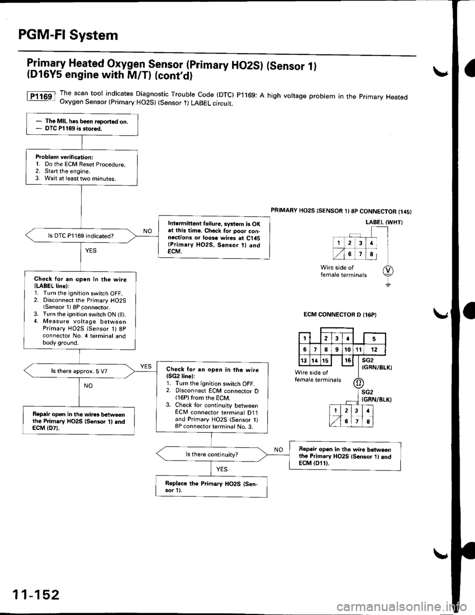
IiT-"-w Heated 9{ygglSensor (primary HO2SI (Sensor 1)(Dl6Y5 engine with M/Tl lconr'd)
1T1163 Ih" scan tool indicates Diagnostic Trouble code (DTc) P1169: A high volrage probtem in the pnmary Heated- Uxygen Sensor {primary HO2S) (Sensor .l) LABEL circuit.
PSTMARY HO2S (SENSOR 1l8p CONNECTOR (145)
LABEL IWHTI
ECM CONNECTOR O {16P}
(GRN/BLK)
female
IGRN/BLKI
- The MIL hrs been reported on.- DTC Pl169 i3 stored.
Problem verification:L Do the ECM Reset Procedure.2. Start the engine.3. Wait at least two minutes.
Intormittent f.ilure, sv*em b OKat this time. Check for poor con-n.ctions or loose wires at C145(Prim.ry HO2S, Sensor 1l andECM.
ls DTC P1169 indicated?
Ch€ck Ior an op6n in th€ wire(LABEL line):1. Turn the ignition switch OFF.2. Disconnect the Primary HO2S(Sensor 1) 8P connector.3. Turn the ignition switch ON (ll).4. Measure voltage betweenPrimary HO2S lsensor 1) 8Pconnector No, 4 terminal andbody ground.
Check lor an open in the wire{SG2linel:1. Turn the ignition swilch OFF.2. Disconnect ECM connector D(16P)trom the ECM.3. Check for continuity betlveenECM connector terminal D1land Primary HO2S (Sensor 1)8P connector terminal No. 3.
ls there approx. 5 V?
Ropair opon in the wires betweonlhe P.imary HO2S {Sensor 't} andECM tD7l.
R€pair open in th6 wire betweenthe Primary HO2S lsensor 1) andECM (011).
ls there continuity?
Roplace the Primary HO2S (Sen-sor 1).
123a5
689101t12
t3141516sG2
side ofe terminalstll
II-- rl
;G2
I2
6
34
8
11-152
Page 423 of 2189
PGM-FI System
I
a
a
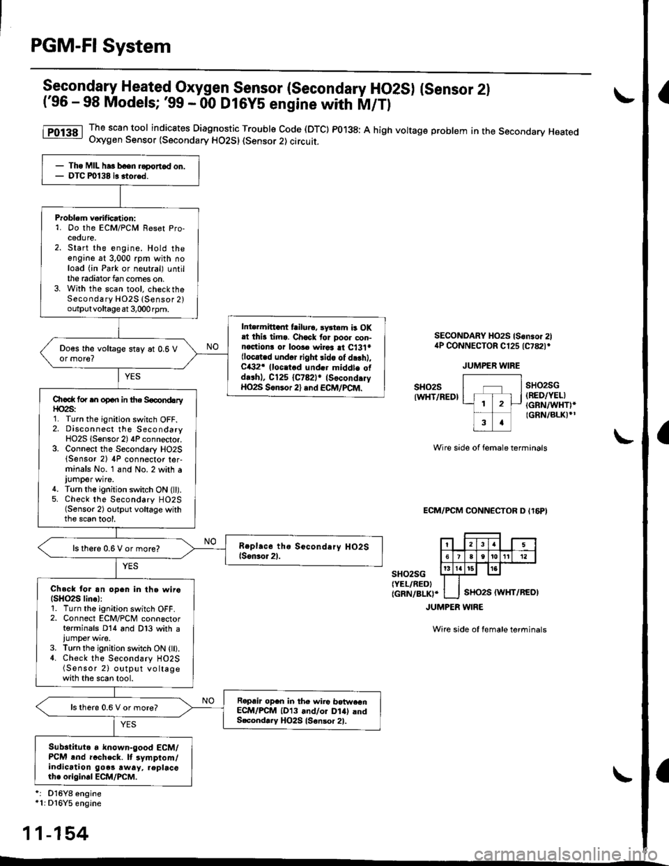
9ggoqOfry Heated Oxygen Sensor (Secondary HO2S) {sensor 2l('96 - 98 Models; '99 - 00 D16YS engine with M/Tl
The scan tool indicates Diagnostic Trouble Code (DTC) PO'138: A high voltag€ problem in the Secondary HeatedOxygen Sensor (Secondary HO2SI (sensor 2) circuit.
SECONDARY HO2S ls.nsor 2l4P CONNECTOR C125 tc782t*
JUMPER WIRE
sHo2sIWHT/RED}
sHo2sG(RED/YEL)(GRN/WHT)*(GRN/BLK)*'
Wire side of female terminals
ECM/FCM CONN€CTOR D Il6PI
sH()2sG{YEL/RED){GRN/BLK}'
JUMPER WINE
Wire side of female terminals
'i D16Yg engine*1i Dl6Y5 engine
- Ths MIL ha3 bcen r6port.d on.- DTC m138 i. 3tored.
Problem vorilication:1. Do the ECM/PCM Reset Pro-cedure.2. Start the engine. Hold theengine at 3.000 rpm with noload (in Park or neutral) untilthe radiatorfan comes on.3. With the scan tool, ch€cktheSecondary HO2S {Sensor 2)outputvoltageat 3,000rpm.
Into.mittant failurc, sy3tem b OKrt thi3 tims. Ch6ck tor poor con-n6clionr or loo3€ wiroa at C13'l*(locat d und6r right lido of dr'h),C/€2r (loc.tod und€r middle old.rhl, C125 {C782lr (Socond.ryHO2S S6n3or 2) .nd ECM/PCM.
Chcd( for rn open in the Socond!ryf|o2s:1. Turn the ignition switch OFF.2. Disconnect the SecondaryHO2S (Sensor 2) 4P connector.3. Connect the Secondary HO2S(Sensor 2) 4P connector ter-minals No. 1 and No.2 with aJUmper wire.4. Tu.n the ignition switch ON (ll).5. Chock the Secondary HO2S(Sensor 2) output vollage withthe scan tool.
ls there 0.6 V or more?
Check tor an open in the wiro(SHO2S lin6l:1. Turn th6 ignition switch OFF.2. Connect ECM/PCM connectorterminals D14 and D13 with ajumper wire.3. Turn the ignition switch ON {ll}.4. Check the Secondary HO2S(Sensor 2) oltput voltagewith the scan tool.
Rapair op.n in the wiio botw.onECM/PCM lD13 and/or Dlal andS.cond.ry HO2S ls€nsor 21.
ls thore 0.6 V or more?
Subslituto a known-good ECM/PCM .nd rccheck. lt symptom/indication goe! rway, replacethe original ECM/PCM.
11-154
Page 424 of 2189
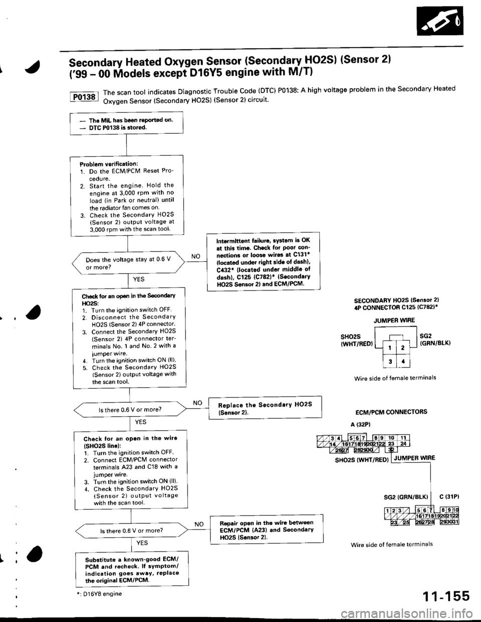
Secondary Heated Oxygen Sensor (SecondarytlO2S) (Sensor 2l
('99 - 00 lilodels except DtGYS engine with M/T)
The scan tool indicates Diagnostic Trouble code (DTC) P0138: A high voltage problem in the secondary Heated
Oxygen Sensor (Secondary H02S) (Sensor 2) circuit.
SECONDARY HO2S {S€nsot 2}
4P CONNECTOR Cl25 lc782l'
JUMPER WIRE
Ir
sH02s(WHT/RED)sG2{GRN/BLKI
Wire side of female termanals
ECM/PCM CONNECTORS
A (32P1
Wire side ot female termlnals
gs92g 111yp17p5py | .lutuPea wtne
- The MIL has beon reportod on.- DTC m138 is.tored.
Ploblem vorification:1. Do the ECM/PCN4 Reset Pro-
cedure.2. Start the engine Hold the
engine at 3,000 rpm with no
load (in Park or neutral) until
the radiator{an comes on
3. Check the SecondarY H02S(Sensor 2) output voltage at
3,000 rpm with the scan tool
lntormittont failuio, sYstom b OK
st thir timo. Check for Poor con_
nections ot loo39 wiJo3 af Cl3lr(located under right ride ot desh),
C432' (locatod undot middle of
dashl, Cl25 {C782lr (Secondaiy
HO2S Son3or 2l and ECM/PCM.
Does the voltage stay at 0 6 V
or more?
Ct€d( tor an opan in the Secondary
l|o2s:1. Turn the ignition switch OFF
2. Disconnect the SecondarY
HO2S (Sensor 2) 4P connector.
3. Connect the Secondary HO2S(Sensor 2) 4P conneclor ter_
minals No. 1 and No.2 with a
iumper wire.4. Turn the ignition switch ON (ll)
5. Check the SecondarY HO2S
lSensor 2) outptlt voltage with
the scan tool,
lsthere 0.6 V or more?
Check lor an open in the wiro(SHO2S line):1. Turn the ignition switch OFF.
2. Connect ECM/PCM connector
terminals A23 and C18 with ajumper wrre,
3. Turn the ignition switch ON (ll).
4. Check the SecondarY HO2S
{Sensor 2) outPut vo ltage
with the scan tool.
Repair opon in tho wire betwecn
ECM/PCM (A23) and SocondarY
HO2S {Sansor 2).ls there 0.6 V or more?
Substitut€ a known'good ECM/
PCM and recheck. It symptom/indication goes awey, JePlaco
the otiginel ECM/PCM
*i 016Y8 engine1 1-155
Page 442 of 2189

(From page | 1-172)
Check fo. a sho.t in the CKP/
TDC/CYP sensor:Check for continuity to bodYground on both terminals of the
indicated senso r individually
1*see table).
Replaco the di3tributor ignition
hoGing lsee section 23).ls there continuity?
Check for an open in the wires
ICKP/TOC/CYP line3):1. Reconnect the distributor 10P
connecaor.2. Disconnect the EcM/PCM con-
nector C {31P}.3. N4easure resistance betweenthe terminals of the indicated
sensor on the ECIM/PCM con-
nector {*see tabie}.
Repair open in the indicated sen-
sor wires lrsee tablel.ls there 350 - 700 o?
Chock lor. short in the wires
ICKP/TDC/CYP lines):
Check for continuity between
body ground and ECM/PCM con-
nector terminals C2, C3 and/or C4individually.
Repai. short in the indic.ted sen_
sor wire3 ('soe tablol,ls there continuity?
Substitute e known-good ECM/PCM, and iecheck. ll sYmptom/indication goes awev, r€Place the
original ECM/PCM.
DISTRIBUTOR10P CoNNECTOR {C1201
Terminalside ofmale terminals
ECM/PCM CONNECTORS C 131P)
CI(P P TDC P CYP P(YEL)
M
CKP M(WHT)MIBLKI
Wire side offemale terminals
CYP PIYELI
(REDI
TDC P(GRN)CKP P(BLU}
t
TDC P (GRNI
11-173
Page 479 of 2189
ldle Control System
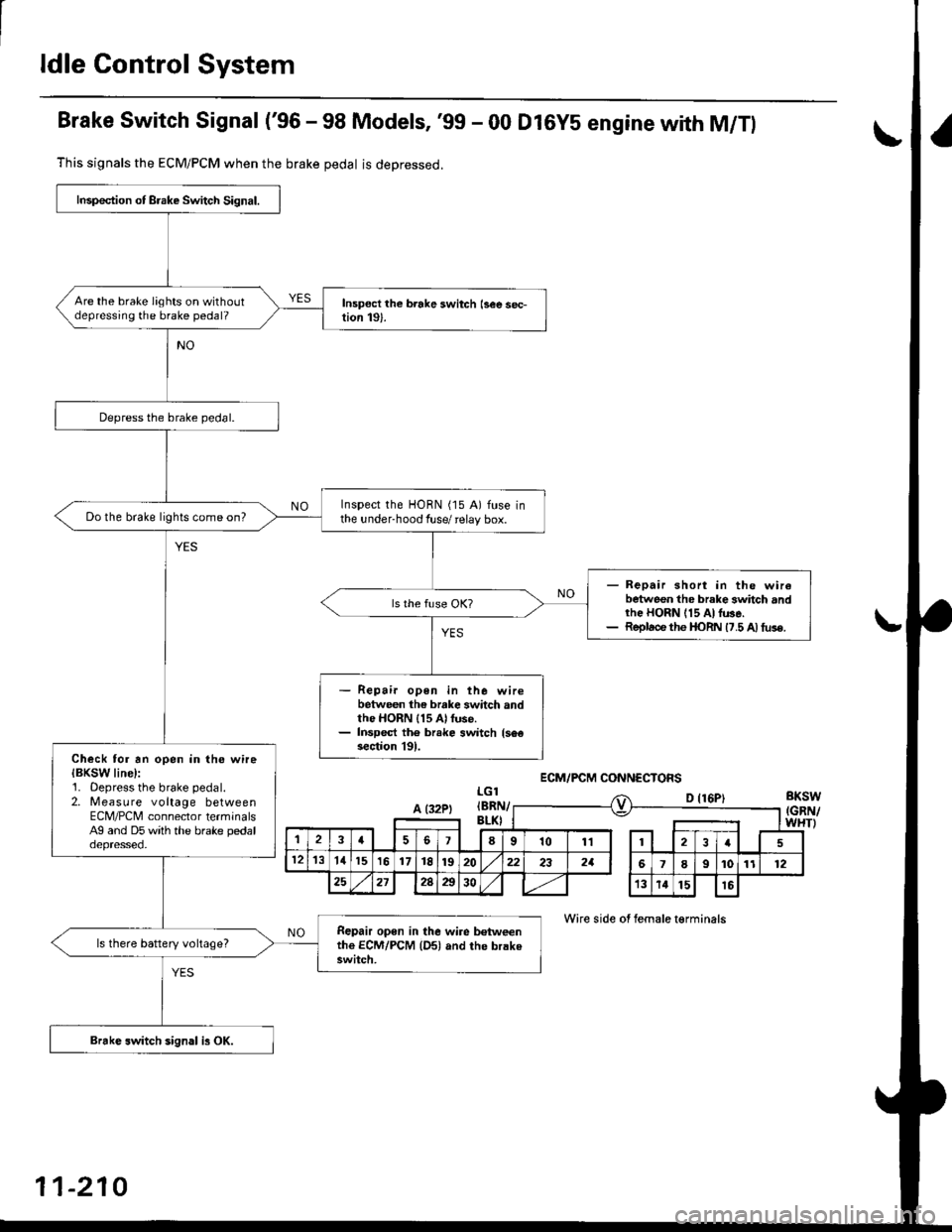
Brake Switch Signal ('96 - 98 Models, '99 - 00 Dl6YS engine with M/Tl
This signals the ECM/PCM when the brake pedal is deoressed.
LGlBKSW(GRN/WHTI
D {16P)
Wire side of female t€rminals
Inspection of Brake Switch Signal.
Are the brake lights on withoutdepressing the brake pedal?
Depress the brake pedal.
Inspect the HORN (15 A) fuse inthe under-hood fuse/ relay box.Do the brake lights come on?
- Repair short in the wirebetween the brake 3whch andrhe HORN 115 At lu3e.- Replace the I|oRN 17.5 A) tus€.
Repair open in the wirebetween the brake switch andthe HORN 115 Al fuse.Inspect th6 br.ke switch {s6€section l9l.Check tor an open in the wireIBKSW line):1. Oepress the brake pedal.2. Measure voltage betweenECM/PCNI connector terminalsAg and D5 with the brake pedaloepresseo.
Repair open in the wire b€tweenthe ECM/PCM {Dsl and the brakeswitch.
ls there battery voltage?
Brakc switch sign.l is OK.
ECM/PCM CONNECTOFS
A (32PtIBRI\v
,la678101112I
121311151617t8192022232aI9101112
25212Aa3013141516
11-210
Page 480 of 2189
IJBrake Switch Signal ('99 - 00 Models except Dl6Y5 engine with M/Tl
This signals the ECM/PCM when the brake pedal is depressed
I
lnsoection ot Brake Switch signal.
Are the brake lights on without
depressing the brake Pedal?
Depress the brake Pedal
Inspect the HoRN {15 A} fuse in
the underhood fuse/ relay box'Do the brake lights come on?
- R.pair short in the wiro be'
tween the brake switch and
the HORN (15 Alfuse.- Replac€ the HORN (15 A) tuse.
- Repair open in the wite be'
tween the brako switch and
the HORN (15 Alfuse.- lnsoect the brake switch (3ec
section tgl.
Check fot an oPen in the wire
{BKsw linel:
1. Depress the brake Pedal.2. Measure vohage beween ECM/
PCM connector terminals A32
and 820 with the brake Pedaldepressed.
Bepair open in the wire between
the ECM/PCM (A32) and the
brake switch.
Brake switch signal i5 OK
ECM/PCM CONNECTORS
BKSW (GRN/WHTI
LG1 {BRN/BLK)
Wire side o{ female terminals
Page 527 of 2189
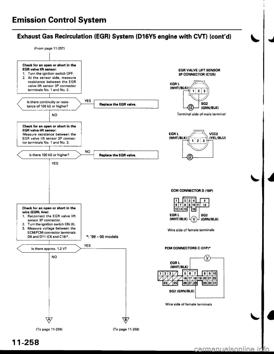
Emission Gontrol System
Exhaust Gas Recirculation (EGRI System (Dl6Y5 engine with CW) (cont'dl
EGR VALVE LIFT SENSOR3P CONNECTOR {Cl251
./
EGR L(WHT/BLKI
EGR LIWHT/BLKI
EGR L{WHT/BLKI
sG2
{GRN/BLK}
sG2{GRN/BLK}
Terminal side ol male terminal
ECIT'I CONNECTOR D II6PI
Wir€ side of f€male terminals
PCM CONNECTORS C (31PI*
{To page 11-259)
11-258
{From page 11-257}
Chock lor an opcn or short in th.EGR v.lve lift .€nsor'1. Turn the ignition switch OFF.2. At the sensor sid€, measur€resistance between the EGRvalve lift sensor 3P connectorterminals No. 1 and No.2.
ls there continuity or resis'tance ot 100 k0 or higher?
Chock tor sn op€n or lhort in theEGR valve lift lonror:Measure resistancg between theEGR valve lift s€nsor 3P connec-tor terminals No. 1 and No. 3.
ls there 100 k0 or higher?
Ch.ck tor an ooon or rhon in thcwiro IEGRL linc):1. Beconnect tho EGR v6lve liftsensor 3P connector.2. Turn tho ignition switch ON (ll).
3. Measure voltage between theECM/PCM connector terminalsD9 and Dl1 (C6 and C18l*.
ls there approx. 1.2 V?
(To page 11-259)
Wire side of female terminals