Page 1379 of 2189
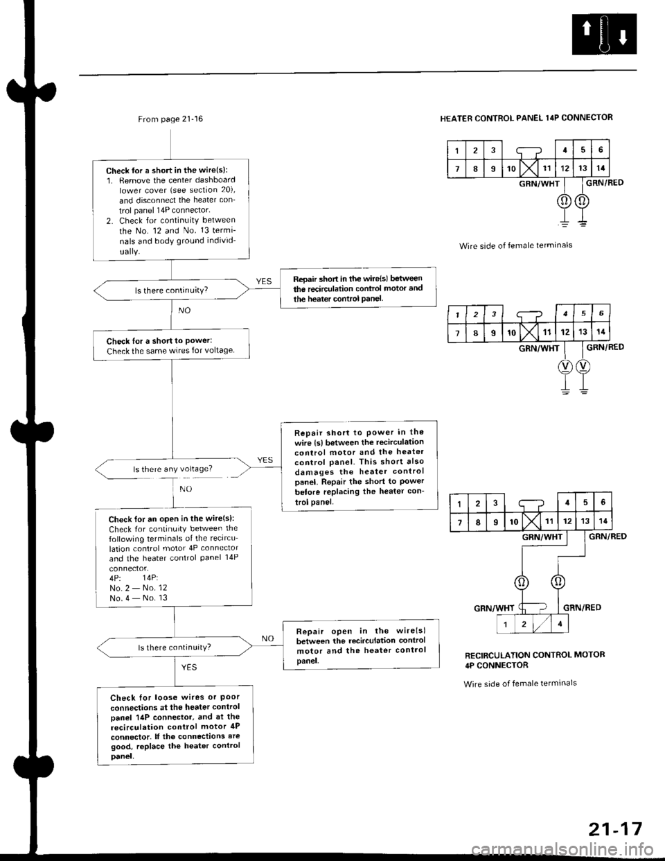
'99 - 00 Models
UNDER,HOOO FUSE/RELAY 8OX
PUSN SWITCH
lHce nvosrar F)- aLu neo(Wirh IVC)
DASH LIGHTS -/1BBTGNTNESS < l- FEoCONTROLLER -!
IGN TION SW TCHUNDEF DASHFUSElRELAY BOX
**,',,* **",@ ",.
@f
u,n,",,
ELUAVHT
I
YBLUi BtK
BLOWERMOTOR
ELOWERMOTORHIGHRELAY
PNK/BLK
FED''WHT
RED,YEL
GRY
BRN
YEL
YEL/FEO
6RNiYEL
8LU/!VHT
YEL/BLU
BRNfiHT
GFNM/HT
GRNi FED
O :8P CONNECTOR
! :20P CONNECTOF
E : 12P CONNECToR
BLUi BLK
1
tic
HEATER CONTROL PANEL
VENT
MOOEHEAT CONTFOLMOTOF- M.COMDEF
[[f&H,,4*,",,
BLK
Page 1381 of 2189
Heater Control Panel Input/Output Signals
HEATER CONTROL PANEL lilP CONNECToR
Wire side of lemale terminals
21-7
Terminal
No.
Wire
colorSignalTerminal
No.
Wire
colorSignal
1YELHEAT/DEFINPUT8YEVREDVENTINPUT
BLfiELINPUT9G RNI/ELHEATIr'ENTINPUT
WHT/BLU+BINPUT'10BLKGROUNDOUTPUT
4YEUBLUDEFINPUT11*BLU/REDA./C THERMOSTATINPUT
5REDDASH LIGHTS
BRIGHTNESS CONTROLLEROUTPUT12GRN/WHTFRESHINPUT
6RE D/8LKCOMBINATION LIGHT
SWITCHINPUT13GRN/REDRECIRCULATEINPUT
1BLUMHTHEATINPUT14GRNHEATER FAN SWITCHOUTPUT
Page 1391 of 2189

From page 21-16
ls there any voltage?
Check {or a short in the wire(s):1. Remove the center dashboardlower cover (see section 20),
and disconnect the heater con_
trol panel 14P connector'
2. Check for continuity between
the No. 12 and No. 13 termi-
nals and body ground individ-
Repair 5hort in the wire{sl between
the recirculation control motor and
the heater control Panel
Check Ior a short to Power:Check the same wires for voltage
Repair short to Power in the
wire {s) between the recirculationcontrol motor and the heater
control panel. This short also
damages the heater controlpanel. Repair the short to Powerbetore replacing the heater con-
trol panel.
Check lor an open in the wire(s):
Check for continuity between the
following terminals of the recircu
lation control motor 4P connector
and the heater control Panel 14P
4P. 14P:No.2 - No. 12No.4 No. 13
Repair open in the wirelsl
between the recirculation control
motor and the heater controlpanel.
ls there continuitY?
Check for loose wires or Poorconnections at the heater control
Danel 14P connector, and at the
recirculation control motor 4P
connector. lf the connections aregood, replace the heater control
Danel,
HEATER CONTROL PANEL 14P CONNECTOR
I;-?45
789'o lx11121314
GRN/WHT
0) (0
GRN/BED
Wire side of female terminals
GRN/RED
GRN/RED
RECIRCULATION CONTROL MOTOR
4P CONNECTOR
Wire side of female tetminals
I23i--?156
78I'olx11121314
GRN/WHT
V)(v
145
7IIrol\l rr1213
GRN/WHT
r zl/lt
21-17
Page 1402 of 2189

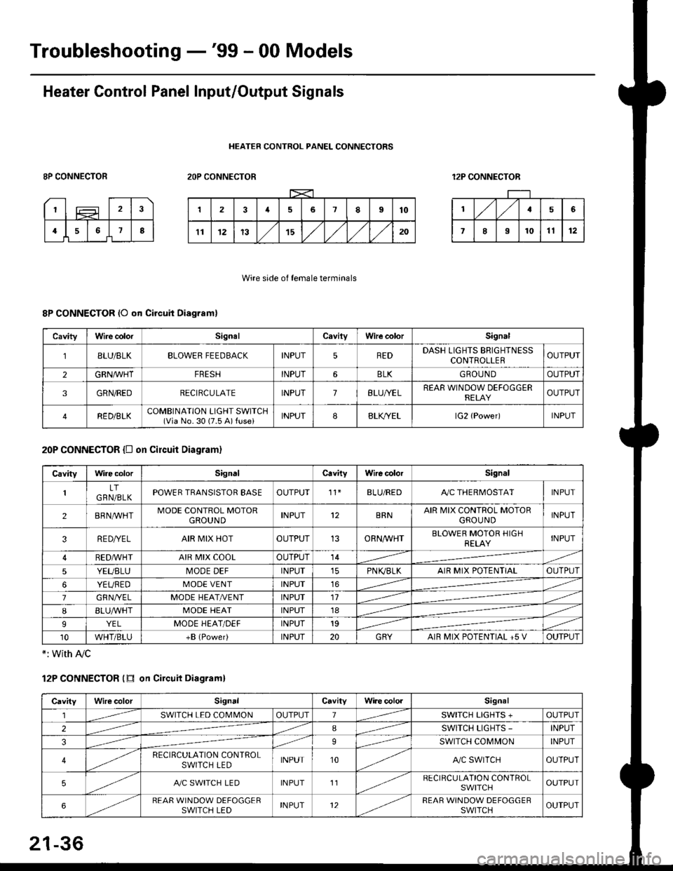
Troubleshooting -'99 - 00 Models
Recirculation Control Motor (cont'd)
Frcm page 21-27
HEATER CONTROL PANEL 8P CONNECTOR
Check for a short to power in the
1. Turn the ignition switch ON {ll).2. Disconnect the heater controlpanel 8P connector.3. Check for voltage between theNo.2 and No. 3 terminals oftheheater control panel 8P con,nector and body ground individually.
Repair 3hort to powe. in thewire{a) b.tween tho haetor con-trol panel and the recirculationGontrol moto.. This short alsodamagos the heate. controlpanel. Repair the short to powerb€tore .eplecing the h€ater con-trol panel.
ls there any voltage?
Check to. a short to ground:1. Turn the ignition switch OFF.2- Check the same terminals forcontinuity to ground.
Roprir lhon in tho wir.{s) b€tweothe horter control panel and theracircr alion conhol motoa.
Check for an open in the wires:1. Disconnect the recirculationcontrol motor 4P connector.2. Check for continuity betweenthe following terminals of therecirculation control motor 4Pconnector and the heater con,trol panel 8P connector.8P: 4PiNo.2 - No.2No.3 - No.4
Repair open in ths wirolsl betw€€nthe heate. co.rkol panol and therecirculation control motor .
Check lor loo3a wires or pootconn€ctions at the hoater controlpanel 8P connector and at theaecirculation control motor ilPconnector, It tho connections aregood. substitut€ e known-goodheatei control panel, and aecheck.lf th€ symptom/indication goesaway, replace the original hedtercontrcl Danel.
GRN/WHT
I1
GRN/RED
RECIRCULATION CONTROL MOTOR4P CONNECTORWire side of female terminals
21-28
Page 1410 of 2189

Troubleshooting -'99 - 00 Models
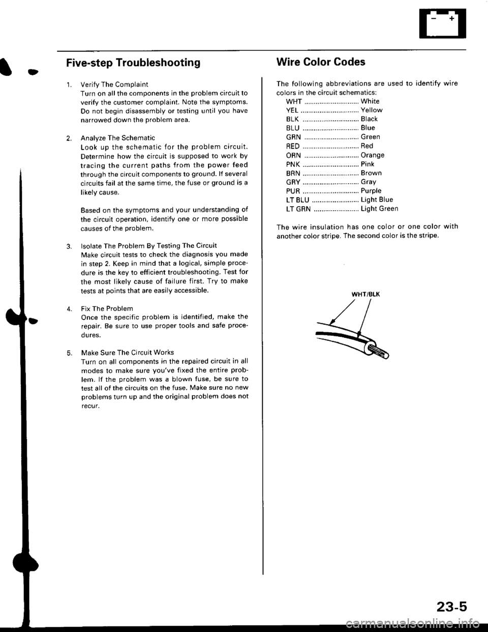
Heater Control Panel Input/Output Signals
HEATER CONTROL PANEL CONNECTORS
8P CONNECTOR2OP CONNECTOR12P CONNECTOR
Wire side of female terminals
8P CONNECTOR (O qn Circuit Diagram)
20P CONNECTOR {D on circuit Diagram}
*: with Ay'c
12P CONNECTOR (tr on Circuit Diagraml
CavityWire colorSignalCavilyWhe colorSignal
BLU/8LKBLOWER FEEDBACKINPUT5REDDASH LIGHTS BRIGHTNESSCONTROLLEROUTPUT
2GRN/lVHTFRESHINPUT6BLKGBOU N DOUTPUT
3GRN/REDRECIRCULATEINPUT7BLU/YELREAR WINDOW DEFOGGERRELAYOUTPUT
4RED/BLKCOMBINATION LIGHT SWITCH(Via No. 30 (7.5 A) fuse)INPUT88LfiELlG2 {Power)INPUT
CavityWire colorSignalCavityWire colorSignal
LTGRN/BLKPOWER TRANSISTOR EASEOUTPUT't1BLU/REDAy'C THERMOSTATINPUT
2BRNMHTMODE CONTROL MOTORGROUNDINPUT12BRNAIR MIX CONTROL MOTORGROU NDINPUT
3RE D/YELAIR MIX HOTOUTPUT13ORNAA/HTBLOWER MOTOR HIGHRELAYINPUT
RED,ryvHIAIR MIX COOLOUTPUT14
5YEUBLUMODE DEFINPUTPN K,/BLKAIR MIX POTENTIALOUTPUT
6YEUREDMODE VENTINPUT16
7GRNI/ELMODE HEAT/r'ENTINPUT11
IBLUAVHTMODE HEATINPUT18
9YELMODE HEAT/DEFINPUT19
10WHT/BLU+B (Power)INPUT20GRYAIR MIX POTENTIAL +5 VOUTPUT
CavityWilecolorSignalCavityWi.e cololSignal
lSWITCH LED COMMONOUTPUT1SWITCH LIGHTS +OUTPUT
2ISWITCH LIGHTS -INPUT
39SWITCH COMMONINPUT
4RECIRCULATION CONTROLSWITCH LEDINPUT10A,/C SWITCHOUTPUT
5A./C SWITCH LEDINPUT11RECIRCULATION CONTROLSWITCHOUTPUT
6REAR WINDOW DEFOGGERSWITCH LEDINPUT12REAR WINDOW DEFOGGEBSWITCHOUTPUT
21-36
Page 1475 of 2189

t
Five-step Troubleshooting
2.
1.Verify The Complaint
Turn on all the components in the problem circuit to
verify the customer complaint. Note the symptoms.
Do not begin disassembly or testing until you have
narrowed down the problem area.
Analyze The Schematic
Look up the schematic for the problem circuit.
Determine how the circuit is supposed to work by
tracing the current paths from the power feed
through the circuit components to ground. lf several
circuits fail at the same time, the fuse or ground is a
likely cause.
Based on the symptoms and your understanding of
the circult operation, identify one or more possible
causes of the problem.
lsolate The Problem By Testing The Circuit
Make circuit tests to check the diagnosis you made
in step 2. Keep in mind that a logical, simple proce-
dure is the key to efficient troubleshooting. Test for
the most likely cause of failure first. Try to make
tests at points that are easily accessible.
Fix The Problem
Once the specific problem is identified, make the
repair. Be sure to use proper tools and safe proce-
dures.
Make Sure The Circuit Works
Turn on all components in the repaired circuit in all
modes to make sure you've fixed the entire prob-
lem. lf the problem was a blown fuse, be sure to
test all of the circuits on the fuse, Make sure no new
problems turn up and the original problem does not
recur.
3.
Wire Color Codes
The following abbreviations are used to identify wire
colors in the circuit schematics:
wHT ............................. White
YEL ............................... Yellow
BLK ............,.,...............81ack
BLU .............................. Blue
GRN .............................Green
RED .......................,...... Red
ORN ............................. Orange
PNK .............................. Pink
BRN .............................. Brown
GRY .............................. Gray
PUR .,.................,.,........ Purple
LT BLU ......................... Light Blue
LT GRN ........................ Light Green
The wire insulation has one color or one color with
another color stripe. The second color is the stripe.
WHT/BLK
23-5
Page 1478 of 2189
Relay and Control Unit Locations
Dashboard: '96 - 97 models
CRUISE CONINOL UNIT
DAYTIMERUNNING LIG}ITSCONTROL UNITlCan!dal
IWire colo.s: GRN/ORN, GRN/RED,l
IWHT, YEL, and BLK I. MOONROOF CLOSE RELAYfwir. colorc: GRN/ORru, Cnru/VeLl
IWHT. GRN/RED, and ALK I
DASH LIGHTS BRIGHTNESS CONTROLLER{Has built-in control unit)
23-8
Page 1480 of 2189
Relay and Control Unit Locations
Dashboard: '98 - 00 models
CRUISE CONTROL UNIT
DAYTIMERUNNING LIGIfiSCONTROL UNITlCrnrda)
DASH LIGHTS BRIGHTNESS CONTROLLER{Has built-in control unit}
STARTEB CUI RELAY
[wi]e color.: BLX/WHT, exnfxf, IIBLU/BLK, |nd BLK/RED j
coloE: WHT/GRN, BLU/REO,IandWHT/GRN I
MOONROOF CLOSE RELAY
fwiro colors: GRN/O8ru. CnrulYel,l
IWHT, GBN/RED, end BLK I
23-10