Page 1623 of 2189

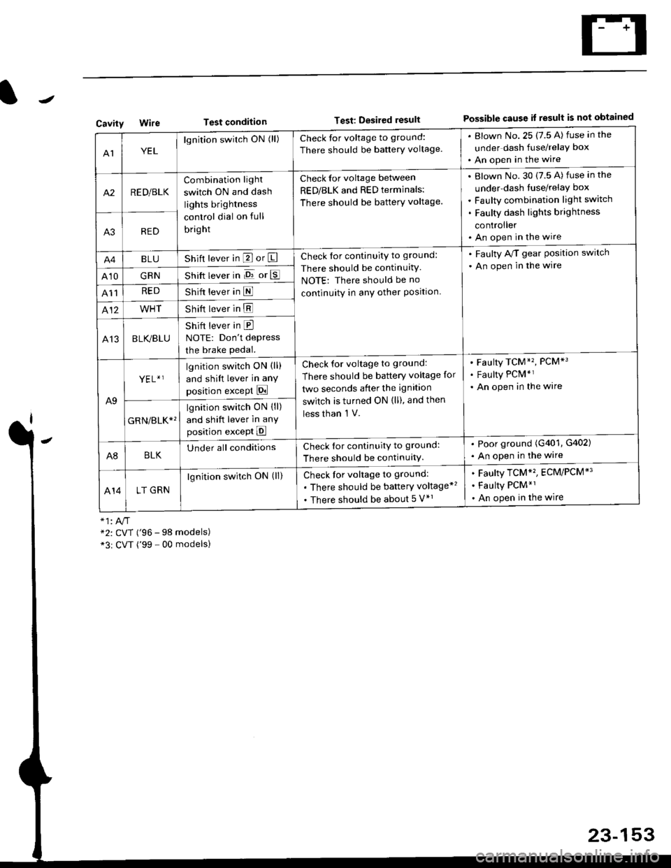
Test conditionTest: Desired resultPossible cause it result is not obtainedCavity
AIYEL
lgnition switch ON (ll)Check for voltage to ground:
There should be banerY voltage.
. Blown No.25 (7.5 A) fuse in the
under dash fuse/relay box
. An open in the wire
A2RED/BLK
Combination light
switch ON and dash
lights brightness
control dial on full
bright
Check for voltage between
RED/BLK and RED terminals:
There should be batterY voltage.
Blown No. 30 {7.5 A) fuse in the
under-dash tuse/relay box
Faulty combination light switch
Faulty dash lights brightness
controller
An open in the wireA3RED
BLUShift lever in P or ICheck for continuity to ground:
There should be continuitY
NOTE: There should be no
continuity in anY other Position.
. Faulty A/T gear Position switch
. An open in the wire
A10GRNShift lever in E or E
A11REDShift lever in E
412WHTShift lever in E
A13BLK/BLU
Shift lever in E
NOTE: Don't depress
the brake pedal.
A9
YEL+ ]lgnition switch ON (ll)
and shift lever in any
position except Pi
Check for voltage to ground:
There should be battery voltage for
two seconds after the ignition
switch is turned ON (ll), and then
less than 'l V.
Faulty TCM*'�, PCM*3
Faulty PCM*r
An open in the wire
GRN/err*'
lgnition switch ON {ll)
and shift lever in anY
position except E
A8BLKUnder all conditionsCheck for continuitv to ground:
There should be continuitY.
. Poor ground (G401, G402)
. An open in the wire
414LT GRN
lgnition switch ON (ll)Check for voltage to ground:
. There should be baftery voltage*'�
. There should be about 5 V*r
Faulty TCM*'�, ECM/PCM*'
Faulty PCM*1
An open in the wire
*2: CVT ('96 - 98 models)*3r CVT ('99 - 00 modelsl
23-153
Page 1634 of 2189
Lighting System
Circuit Diagram (Canada)
UNDER.HOOD FUSEi RELAY BOXBATTERY
BFAKE SYSTEMLIGHTNTEGRATEDCONTROL UNIT
f-7
I
IFED/GRN
REDiGFN
II
o
Yro*, ,,r'oI LEVEL SW TCH
t |
lclosed : Floal downl
BLK
I
-L..
G401G402
T
.:
BLK
n:
G40lG402
BLK
I
G201
RED/GRN RED/GBN
| .+_
ttL
| | las*,
| \_i-f
Alr
Y,o" r.o" I
liiqff'- |BLK BLK
tl
dT--
G401 G202G402
l\------tr -1
d,$,E" T d
RED/BLU RED/REDiGEN
UNDEF DASH FUSE/RELAY BOX
I
)) N0.20tl0Al)'
No.1g(7.5A)No.50 0A)
, ll-l
llltti /i[ii i,II
ll
llri, zll",ll iu"x
TT
FEDiGRN R€D
tl
!-tl--l
ttuLj
il]-
YEL REDTWHT FED/BLU FED/8LK RED/ BLK
tt++
IIVV| | .DASF L.GHTS . oAB(^rG -TGHTSI I .DAS-LGH'S.TALL'GCTS
| | 33''9+il4[','o L.ENSEoLATELTG'TS
I l-,ro,u,rffl,
^-^^-.*^,{*"'"0-
tlI qsnlq,rr DAYT'ME qUNNINGLIGHTS FES STOF
nd--f)
irt* | | Trt* Iorr Itt I---J \---J-------J
-rGHr
lt*"','
I
I
YEL/BLK
DAYTIMERUNNING LIGHTSCONTROL UNIT
RED/GHN R
I
5
[i.mi:-",,,
Page 1636 of 2189

Lighting System
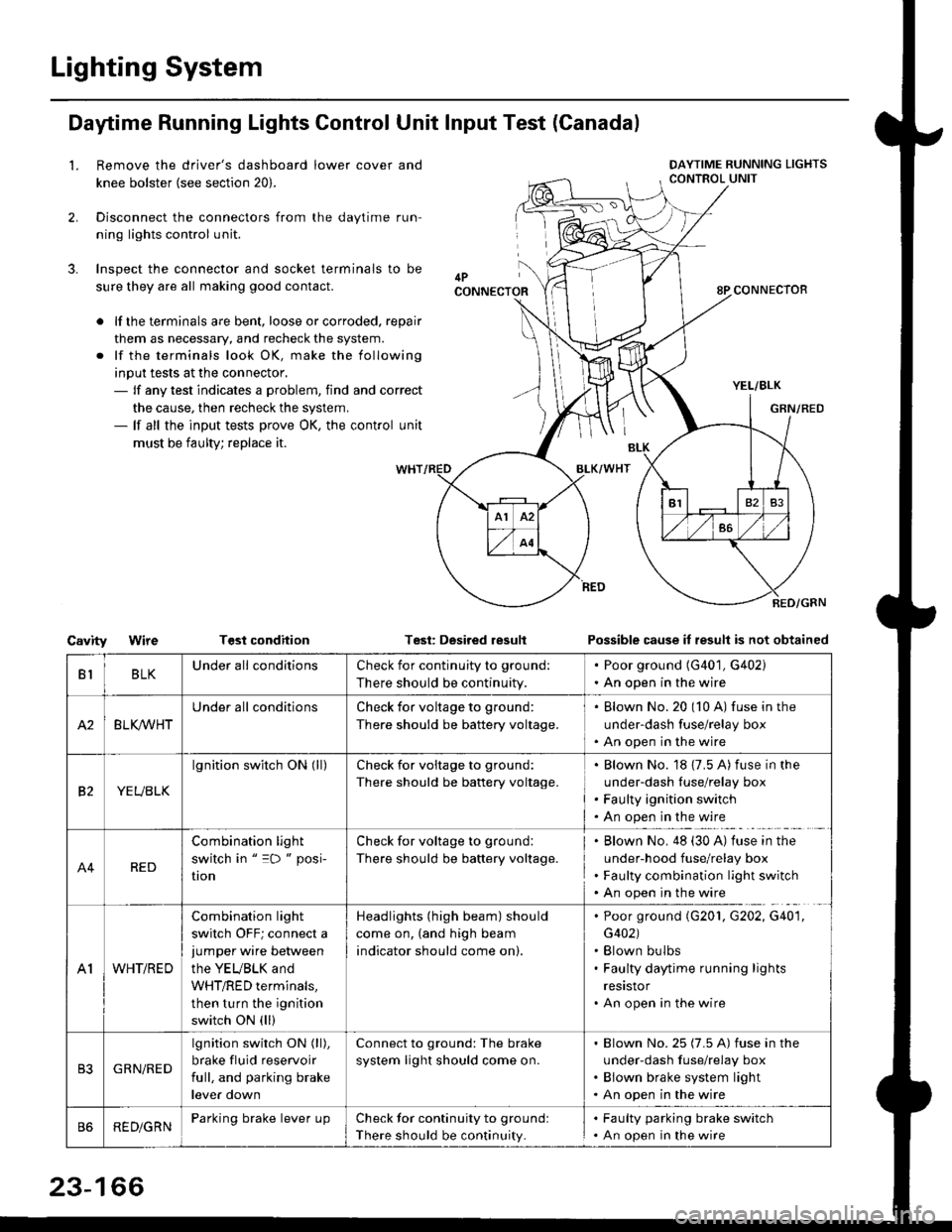
Daytime Running Lights Control Unit Input Test (Canadal
2.
3.
LRemove the driver's dashboard lower cover and
knee bolster (see section 20).
Disconnect the connectors from the daytime run-
ning lights control unit.
Inspect the connector and socket terminals to be
sure they are all making good contact.
lf the terminals are bent, loose or corroded. repair
them as necessary, and recheck the system.
lf the terminals look OK, make the following
input tests at the connector,- lf any test indicates a problem, find and correct
the cause, then recheck the system.- lf all the input tests prove OK, the control unit
must be faulty; replace it.
CavityWireTGst conditionTest: Desired resultPossible cause it result is not obtained
BLKU nderall conditionsCheck for continuity to g.ound:
There should be continuity.
. Poor ground (G401, G402). An open in the wire
A2BLK /VHT
Underall conditionsCheck for voltage to ground:
There should be battery voltage.
Blown No.20 (10 A) fuse in the
under-dash fuse/relay box
An open in the wire
etYEUBLK
lgnition switch ON (ll)Check for voitage to ground:
There should be battery voltage.
Blown No. 18 {7.5 A) fuse in the
under-dash luse/relay box
Faulty ignition switch
An open in the wire
A4RED
Combination light
switch in " =D " posi-
UOn
Check for voltage to ground:
There should be battery voltage.
Blown No. 48 (30 A) tuse in the
under-hood fuse/relay box
Faulty combination light switch
An open in the wire
A1WHT/RED
Combination light
switch OFF; connect ajumper wire between
the YEUBLK and
WHT/RED terminals,
then turn the ignition
switch ON (ll)
Headlights (high beam) should
come on, (and high beam
indicator should come on).
. Poor ground (G201, G202, G40'1,
G402). Blown bulbs. Faulty daytime running lights
resrstor. An open in the wire
GRN/RED
lgnition switch ON (ll),
brake fluid reservoir
full, and parking brake
lever down
Connect to ground: The brake
system light should come on.
Blown No.25 (7.5 A) fuse in the
under-dash f use/relay box
Blown brake system light
An open in the wire
REDiGRNParking brake lever LrpCheck for continuity to groundl
There should be continuity.
. Faulty parking brake switch. An open in the wire
23-166
Page 1654 of 2189
Interior Lights
Circuit Diagram (With Spotlights)
SPOT.LGHTS
2
LT GRNlRED
t_:kr
(Wilh key ess enlry syslem)
t-t
-
, LTGRN/BLKKEYLESS RECEIVERCIBCUIT(ln the aLid o unil)
A
Y""I REARI DooF
t;:x::
| | 333i"
GBN L
A
Ttp;:'
Itsl";g;" I
I3331."..,J:
FFONTPASSENGERSDOORSWITCH
ictoseo : 'l
I Door openI Open :L Door closed _J
x I 3.4W :tiSA, Canada produced5W Japan produced*2 8w W lh moofroot5W Wlho!lmoonroof
23-144
UNDEB HOOD FUSEi RELAY BOX
LTGRN/RED
WHT/REDWHT/RED
r*r
I T 1,,'-1
'F!
I
I8LU/8LK
I
I
| *ttt-
| ,Y.
IBLUlBLK
A
Yiri'n
It3f.r'+m:r:r,lBLK
{
G601 G761 rHalchbac(G601 Coupe/Sedan
LTGRN/RED
Page 1662 of 2189

Stereo Sound System
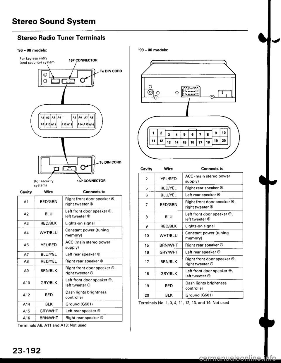
Stereo Radio Tuner Terminals
'96 - 98 models:
For keyless entry . t6p coNNEcroR(and securrty) syslem
To DIN CORD
To DIN CORD
(for securitysystem)
Cavity Wire
A1RED/GRNRight front door speaker o,
right tweeter @
BLULeft front door speaker @,
left tweeter @
A3RE D/B LKLights-on signal
A4WHT/BLUConstant power (tuning
memoryl
A5YEL/REDACC (main stereo power
suppry)
A7BLUI/ELLeft rear speaker O
A8RE DI/E LRight rear speaker O
A9BRN/BLKRight front door speaker O,
right tweeter o
A10GRY/BLKLeft tront door speaker O,
left tweeter O
412REDDash lights brightness
controller
A14BLKGround (G501)
415GRYMHTLeft rear speaker O
Al6BR N/VVHTRight rear speaker O
Terminals A6, A11 and A13: Not used
23-192
'99 - 00 models:
CsvityConnccts toWire
2YEL/REDACC (main stereo power
suppry)
5RE DI/E LRight rear speaker @
BLUI/ELLeft rear speaker @
7RED/GRNRight front door speaker @,
right tweeter @
8BLULeft front door speaker @,
left tweeter @
9RED/BLKLights-on signal
10WHT/BLUConstant power (tuning
memory)
15BRN,ryVHTRight rear speaker O
GRYMHTLeft rear speaker O
17BRN/BLKRight front door speaker O,
right tweeter O
18G RY/BLKLeft front door speaker O,
left tweeter O
'19REDDash lights brightness
controller
20BLKurouno t(l5u t,
Terminals No. 1, 3, 4, 11,12, 13, and 14: Not used
Page 1666 of 2189
Horn
Component Location Index
SRS components are located in this area. Review the SRS component locations, precautions, and procedures in the SRS
section (24) before performing repairs or service.
CABLE REELReplacement, section 24
(:-, ,,/ t.\
(6\'
\K2
HORN RELAY: '98 - 00 models-
lWire colorsr WHT/GRN, cBY,lIWHT/GRN, BLU/RED ]Test, page 23 87
HORN RELAY: '96 -97 models-lwire colors: WHT/GRN. GBY,I
IWHT/GRN, BLU/RED ITest, page 23-86
UNDER-DASH FUSE/RELAY BOX
23-196
Page 1667 of 2189
Circuit Diagram: '96 - 97 models
HORNRELAY
WHT/GRN
I(H)HoRN
Y
IBLU/REO
I
I
IBtK
I
t-l
G40lG1A2
BATTERY
l-
23-197
Horn Test: '96 - 97 models
1. Remove the front bumper (see section 20).
2. Disconnect the 2P connector from the horn.
Remove the horn.
Test the horn by connecting battery power to one
terminal and grounding the other, lf the horn fails to
sound, replace it.
3.
LOW HORN
Page 1668 of 2189
Horn
Circuit Diagram: '98 - 00 models
HCRI]tEtA'a
BATTEFY
1 '98 model: WHT/GRN'99 - 00 modelsr BLU/RED
23494
Horn Test: '98 - 00 models
'1. Remove the f.ont bumper (see section 20).
2. Disconnect the 1P connector from the horn.
TERMINAL
Test the horn by connecting
termina I and grounding the
horn fails to sound, replace it.
battery power to the
mou nting bolt. lf the