Page 110 of 2189

Engine Removal/lnstallation
Installation (cont'd)
Except CVT:
12 x 1.25 mm64 N.m (6.5 kgd.m,
Tighten the bolts/nut on the left front mount in thenumbered sequence shown {O - @).
(t 12 x 1.25 mm83 N'm (8.5 kgf.m,61 tbt.trl
/+4 N.m 14.5 kgf.m,33 lbt.trl
O 12 r 1.25 mm59 N.m 16.0 kgt.m,43 tbt.rtlSeplace.
5-16
\
7. Perform the following:
. Clean the areas where the driveshaft(s) and theintermediate shaft contact the transmission (dif_ferential) thoroughly with solvent or carburetorcteaner, and dry with compressed air.. Check that the set rings on the ends of the drive_shaft and intermediate shaft click into place.CAUTION: Use new set rings,. Adjust the shift cable (see section 14).. Adjust the throttle cable (see section 11).. Adjust the cruise control cable (see section 23).. Refill the engine with engine oil (see page 8-6).. Refill the transmission with fluid (see section 13,14).
. Refill the radiator with engine coolant (see page10-7).
. Bleed air from the cooling system with the heatervalve open (see page j0-7).
. Clean the battery posts and cable terminals withsandpaper, assemble them, then apply grease toprevent corrosaon.. Inspect for fuel leakage (see section j l).After assembling the fuel line, turn on l) the igni_tion switch (do not operate the starter) so that thefuel pump runs for approximately two secondsand the fuel line pressurizes. Repeat this opera_taon two or three times, then check for fuel leak_age at any point in the fuel line,
Page 256 of 2189
Cooling
fllustrated Index ."..."... ""' 10-2
Radiator
Replacement .'....'...."..."
Engine Coolant Refilling and
Bleeding
Cap Testing
Testing
Thermostat
Replacement .............'....
Testing
10-6
10-7
10-9
10-9
10-10
10-10
Engine Goolant TemPerature
(ECT) Switch
Testing """ 10-11
Water PumP
fffustrated Index ......'... " 10-12
Inspection ' 10'14
Replacement ..'..'...."...'.'....'..'.....'.""" 10-14
!
Page 257 of 2189

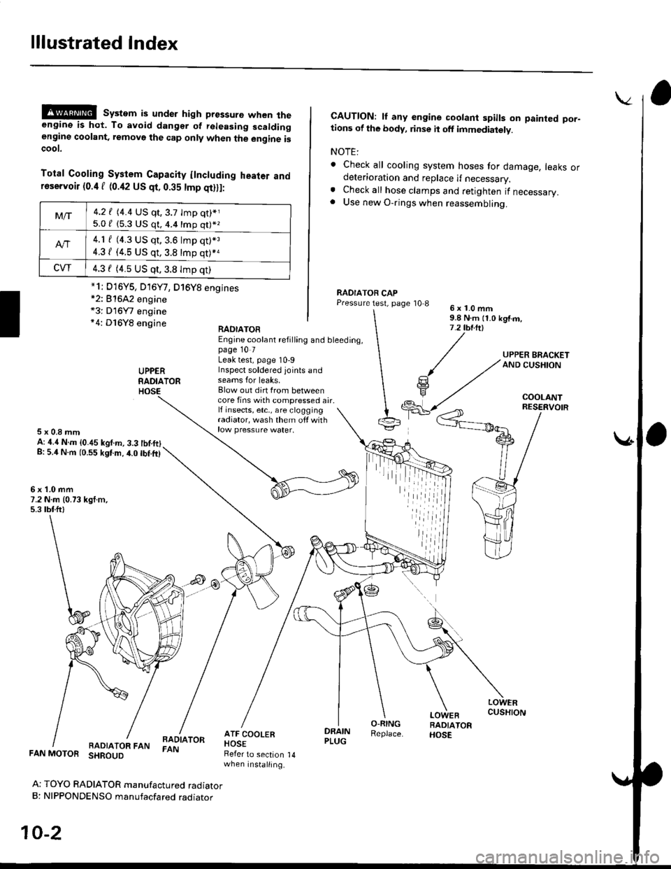
lllustrated Index
@@ system is under high pressure when theengine is hot. To avoid dangsr of rsleasing scaldingengine coolant, removo the cap only when the engine iscoot.
Total Cooling System Capacity flncluding heater andfoservoir (0.4 f (0.42 US qt, 0.35 tmp qt)ll:
*2: 81642 engine*3: D16Y7 engine*4: D16Y8 engine
CAUTION: lf any engine coolant spills on painted por-tions of the body, rinse it off immediately.
NOTE:
. Check all cooling system hoses for damage, leaks ordeterioration and replace if necessary.. Check all hose clamps and retighten if necessary.. Use new O-rings when reassembling.
RADIATOR CAPPressure test, page '10 86x1.0mm9.8 N.m {1.0 kgtm,7.2 tbt.ltl
UPPERRADIATORHOSE
UPPER BRACKETAND CUSHION
COOLANT
RAOIATOREngine coolant refilling and bleeding,page 10 7Leak test, page 10-9Inspect soldered joints andseams for leaks,Blow out dirt Irom betweencore fins with compressed air.lf insects, etc,, are cloggingradiator, wash them off withrow pressure water.
RESERVOIR
5x0.8mmA: ,1.4 N.m {0.45 kgf.m, 3.3 tbtftlg: 5.4 N.m (0.55 kgtm.4.0 tbf.ft)
6x1.0mm7.2 N.m (0.73 kgt.m,5.3 tbtftl
LOWERCUSHION
RADIATOR FANBADIATORFAN
DRAINPLUG
O-RINGReplace.
LOWEBRADIATORHOSE
FAN MOTOR SHROUD
Ar TOYO RADIATOR manufactured radiatorB: NIPPONDENSO manufacfared raoraror
10-2
Refer to section 14when installing.
Mt-|-4.2 f (4.4 US qt,3.7 tmp qt)*j
5.0 / (5.3 U$ q1, 4.4 16p q11*z
4.1 f (4.3 US qt, 3.6 lmp q0*3
4.31 (4.5 US qt, 3.8 tmp qt)*a
CVT4.3 f (4.5 US qt,3.8 Imp qt)
*1i D16Y5, D16Y7, D16Y8 engines
iil
Page 261 of 2189
Radiator
Replacement
Drain the engine coolant.
Remove the upper and lower radiator hoses, andATF cooler hoses.
Disconnect the fan motor connector.
Remove the radiator upper bracket, then pull up theraotator,
RADIA
ATF COOLERHOSES (A/T)Refer to sectionwhen installing.
UPPER RAOIATOR HOSE
6x1.0mm7.2 N.m (0.73 kgf.m.5.3 tbf.ft)
1.
2.
3.
5. Remove the fan shroud assemblies and other partsfrom the radiator.
Install the radiator in the reverse order of removal:
NOTE:
. Set the upper and lower cushions securely.. Fill the radiator with engine coolant and bleedthe air.
6x1.0mmCAPY|lT,PS:|" i.i ru- ii b rgr.-,AND CUSHION7.2 tbr.ftl
14
(
I
RESEBVOIR TANK
RADIATOR
LOWER CUSHION
RAOIATOR FAN/SHROUDASSEMBLY
DRAIN PLUGO-RINGReplace.
LOWER RAOIATOR HOSE
ATF COOLERPIPES {A/T)
,iiiiii
10-6
Page 262 of 2189
tl
Engine Coolant Refilling and Bleeding
CAUTION: when pouring engine coolant, be sure to
shut the relay box lid and not to lst coolant spill on the
eleqtrical parts or the paint. lf any coolant spills, rinse it
off immediately.
1. Slide the heater temperature control lever to maxl-
mum heat. Make sure the engine and radiator are
cool to the touch.
Remove the radiator caP.
Loosen the drain plug, and drain the coolant'
Remove the drain bolt from the cylinder block'
D16Y5. D16Y7, Dl6Yg sngines:
DRAIN PLUG
0d
I ro
78 N.m {8.0 kgl m.58lbt'ft)
6.
1.
B1642 engin€:
WASHERReplace.
DRAIN BOLT78 N m (8 0 kgf m' 58lbfft)
Apply liquid gasket to the drain bolt threads, then
reinstall the bolt with a new washer and tighten 't
securely.
Tighten the radiator drain plug securely
Remove, drain and reinstall the reservoir' Fill the
tank halfway to the MAX mark with water, then up
to the MAX mark with antitreeze.
(cont'd)
10-7
MAX MARK
Page 263 of 2189

Radiator
Engine Coolant Refilting and Bleeding (cont,dl
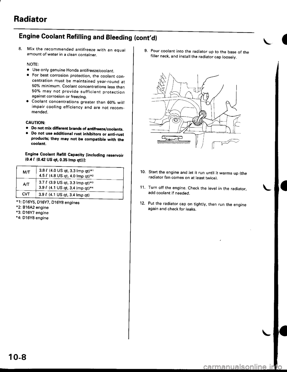
8. Mix the recommended antifreeze with an eoualamount of water in a clean container.
NOTE:
o Use only genuine Honda antifreeze/coolant.. For best corrosion protection. the coolant con_centration must be maintained year_round at50% minimum. Coolant concentrations less than50% may not provide sufficient protectionagainst corrosion or freezing.. Coolant concentrations greater than 60010 willimpair cooling efficiency and are not recom_mended.
CAUTION:
. Do not mix difforont brands ofar ilreeze/coolants.. Do not use additional rust inhibiiors or anti_rustproduqt3; they may not be compatible with thecoolant.
Engine Coolent Refi
Capacity Iincluding reservoir{0.4 f 10.42 US qr, 0.35 lmp qt),I;
*1: D16Y5, D16Y/, O16Y8 engines*2: 81642 engine*3; Dl6Y7 engine*4: Dl6Y8 engine
M/r3.8 f {4.0 US qt, 3.3 lmp qt)*1
4.5 / (4.8 US qt. 4.0 tmp qt)*,
Att3.7, (3.9 US qr,3.3 tmp qt).3
3.9 / (4.1 US qt,3.4lmp qt)*.
CW3.9 / (4.1 US qt,3.4 tmp qtl
10-8
\.-I
9. Pour coolant into the radiator up to the base of thefiller neck. and install the radiator cap looselv.
Start the engine and let it run until it warms up (theradiator fan comes on at least twicer.
Turn off the engine. Check the level in the radiator.add coolant if needed.
Put the radiator cap on tightly, then run the engineagain and check for leaks.
10.
11.
Page 266 of 2189

EGT Switch
-f
Testing
Replace the thermostat if it is open at room temperature'
To test a closed thermostat:
1, Suspend the thermostat in a container of water as
shown.
THEBMOMETER
THERMOSTAT
Heat the water, and check the temperature with a
thermometer. Check the temperature at which the
thermostat first opens, and at which it is fully open
CAUTION: Do not let the thermometer touch the
bottom of the hot Gonlainel.
Measure lift height of the thermostat when fully
open.
STANDARD THERMOSTAT
Lift height above 8.0 mm (0.31 inl
Starts opsning: 169' - 176'F (76' - 80'Cl
Fully open: 194'F {90"C1
!'o
10-1 1
Testing
!!@ Romoving the EcT swhch while lhs engine
i!-ot can cause the coolant to sPray out, seriously scald-
ing you. Always lst th€ ongine and rediator cool down
before removing ihe ECT switch.
NOTE: Bleed air from the cooling system after installing
the ECT switch (see Page 10-7)
1. Remove the ECT switch from the thermostat hous-
ing (see Page'10-10).
2. Suspend the ECT switch in a container of water as
shown.
Heat the water, and check the temperature with a
thermometer.
CAUTION: Do not let the thermomoter touch tho
bottom of the hot container'
Measure the resistance between the A and B termi-
nals according to the table.4.
Terminal
Oo"rffi
swlTcH
ON196' - 203"F
(91" - 95'C)o--o
OFF
5" - 15'F {3" - 8'C)
lower than the temPera-
ture when t goes on
Page 269 of 2189
Water Pump
Inspection
't.
2.
Remove the timing belt (see section 6).
Turn the water pump pulley counterclockwise.Check that it tarns freely.
Check for signs of seal leakage.
NOTE: A small amount of "weeping,,from the bleedhole is normal.
Dl6Y5, Dl6Y7, D16Y8 engines:
BLEEDHOLE
B16A2 engine:
BLEED HOLE
BLEED HOLE
BLEED HOLE
10-14
Replacement
6x1.0mm
1.Remove the timing belt (see section 6).
Remove the water pump by removing five bolts.
NOTE: Inspect, repair and clean the O-ring grooveand mating surface with the cylinder block.
D16Y5, D16Y7, D16Y8 engines:
12 N.m {1.2 kgf.m, l0 x 1.25 mm8.7 lbt.ft) {4 N.m 14.5 kg{.m.33 tbt.ft)
Bl642 engine:
WATERPUMP
@;2
6x1.0mm12 N.m 11.2 kg{.m,8.7 tbf.ft)
O.RINGReplace.
3. Install the water pump in the reverse order of removal.
NOTE:
o Keep the O-ring in position when installing.. Clean the spilled engine coolant.
d
orp,
I