Page 1679 of 2189

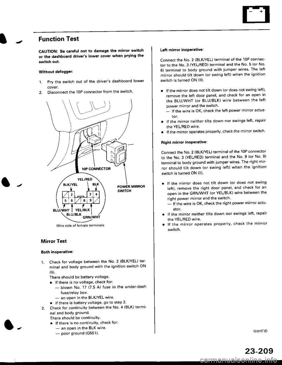
Function Test
CAUTION: Be careful not to damage the mirror switch
or the dashboard drivel's lower covel when prying the
swhch out.
Withoui defogger:
1. Pry the switch out of the driver's dashboard lower
cover.
2. Disconnect the 10P connector from the switch.
lOP CONNECTOR
BLU/WHT
YEL/RED
BLK/YELBLK
4
568
YEL/BLK
POWER MIRRORswtTcH
\:/"*jgil*-(
Wire side of female termanals
Mirror Test
Both inoperative:
1. check for voltage between the No. 2 (BLVYEL) ter
minal and body ground with the ignition switch ON
0 r).
There should be batterY voltage
. If there is no voltage, check for:
- blown No. 17 (7 5 A) fuse in the under-dash
tuse/relay box- an open in the BLK'/YEL wire.
o lf there is battery voltage, go to step 2.
2. Check for continuity between the No 4 (BLK) termi-
nal and body ground.
There should be continuity.
. lf there is no continuity, check for:
- an open in the BLK wire.
- poor ground (G551).
Left mirror inoporalive:
connect the No. 2 {BLK/YEL) terminal of the 10P connec-
tor to the No. 3 (YEURED) terminal and the No 5 (or No
6) terminal to body ground with jumper wires The left
mirror should tilt down (or swing left) when the ignition
switch is turned ON (ll)
. lf the mirror does not tilt down (or does not swing left),
remove the left door panel. and check for an open in
the BLU/WHT (or BLU/BLK) wire between the left
power mirror and the switch
- lf the wire is OK. check the left power mirror actua-
tor.
lf the mirror neither tilts down nor swings left. repair
the YEURED wire.
lf the mirror operates properly, check the mirror switch'
Right mirror inoperative:
Connect the No. 2 (BLK /EL) terminal of the 10P connector
to the No. 3 (YEURED) terminal and the No. 9 (or No 8)
terminal to body ground with jumper wires The right mir-
ror should tilt down (or swing left) when the ignition
switch is turned ON (ll).
. lf the mirror does not tilt down (or does not swlng
left), remove the right door panel. and check for an
open in the GRN/WHT (or YEUBLK) wire between the
right power mirror and the switch.
- lf the wire is OK, check the right power marror actu-
ator.
. lf the mirror neither tilts down nor swings left. repair
the YEURED wire
. lf the mirror operates properly, check the mirror
switch.
(cont'd)
23-209
Page 1680 of 2189

Power Mirrors
Funstion Test (cont'dl
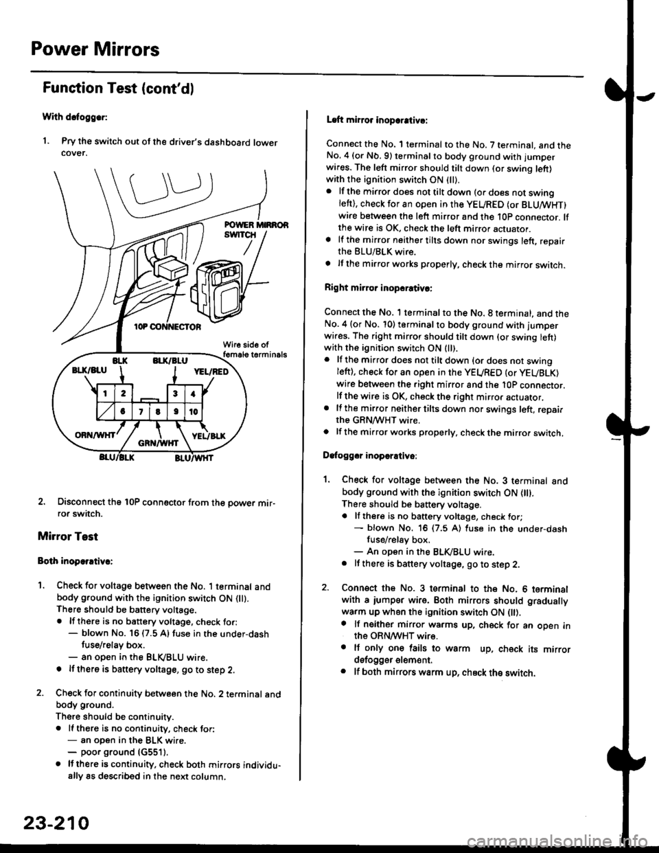
With dcfoggcr:
1. Pry the switch out ot the driver's dashboard lowercover.
2. Disconnect the 10P coonector from the oower mir-ror switch.
Mirror Test
Bolh inoparrtiv.:
1. Check for voltage between the No. 1 terminal andbody ground with the ignition switch ON flt).There should be battery voltage.. lf there is no battery voltage, check to.:- blown No. 16 (7.5 A) fuse in the under-dash
tuse/relay box.- an open in the BLVBLU wrre.
! lf thero is banery voltage, go to step 2.
2. Check for continuity b€tween the No. 2 terminal andbody ground.
There should be continuitv.. ll there is no continuity, check tor:- an open in the BLK wire.- poor ground (G5511.
. lJthere is continuity. check both mirrors individu-ally 8s described in the next column,
23-210
Laft mirror inopcrativ!:
Connect the No. 1 terminal to the No. 7 terminal. and theNo. 4 (or Nb.9) terminalto body ground with jumper
wires. The left mirror should tilt down (or swing left)with the ignition switch ON (ll).
. lf the mirror does not tilt down (o. does not swinglett), check for an open in the YEURED (or BLUMHT)wire between the left mirror and the 10p connector. lfthe wire is OK, check the left mirror actuator.a lf the mirror neither tilts down nor swings left, repairthe BLU/BLK wire.
t lf the mirror works properly, check the mirror switch.
Right mi.ror inopcrativc:
Connect the No. 1 terminal to the No. 8 terminal, and theNo.4 (or No. 10) terminalto body ground with l'umperwi.es. The right mirror should tilt down (or swing lett)with the ignition switch ON (ll).
. lf the mirror does not tilt down {or does not swingleft), check for an open in the YEURED {or YEUBLK)
wire between the right mirror and the l0P connector.lf the wire is OK, check the right mirror actuator,. lf the mirror neither tilts down nor swings left, repairthe GRN/WHT wire.o lf the mirror works properly. check the mirro. switch,
Dafoggcr inoperEtivo:
1. Check for voltage between the No. 3 terminal andbody ground with the ignition switch ON (||).
There should be battery voltage.a lf there is no battery voltage, check for;- blown No. 16 (7.5 A) luse in the under-dash
fuse/rel8y box,- An open in the BLK,iBLU wire.. It there is battery voltage, go to step 2.
2. Connsct the No. 3 tsrminal to the No. 6 terminalwith a iumpsr wire. Both mirrors should gradually
warm up when the ignition switch ON flt).a lf neither mirror warms up, check for an open inthe ORN/WHT wire.. It only on€ lails to warm up, check its mirrordsfogger elem6nt.. lf both mirrors warm up, check ths switch.
Page 1683 of 2189
7.
8.
6. Remove the two screws, cut the wire harness, and
remove the actuator.
Record the terminal locations and wire colors'
Route the wire harness of the new actuator through
the hole in the bracket. Be sure to pass the wlre
under the bracket cliP.
BRACKET
9. Pass the connector boot over the wire harness
23-213
BLK/WHTi
,t
L,
.;{
I
oa
LT GRN I GRY
PNK
10, lnsert the terminals into the connector in the origi-
nal arrangement (recorded in step 7), as shown
Detow.
Right:
SLK/WHT*
BLU/REO'
": Canada '99 - 00 models
Apply tape to seal the intersection of the connector
boot and the wire harness.
Reassemble in the reverse order of disassembly Be
careful not to break the mirror when reinstalling it
to the actuator.
Reinstall the mirror assembly to the door.
Operate the power mirror to check that the actuator
works smoothlY.
Left:
11.
12.
13.
't 4.
PNK
Page 1686 of 2189
Wipers/Washers
Circuit Diagram (Rear Window)
UNDEN HOOD FUSE/RELAY BOX
"l-
WHTi BLK +WI]T
REAF WINDOWWIPERMASHERSWITCH
GRN/BLK
A
IB!K
t-
ouo,G761ooo,G402
,'/-t:<-- -----,-l
23-216
Page 1705 of 2189
Moonroof
a-/
Component Location Index
MOONBOOF SWITCHTest, page 23-236
. MOONROOF CLOSE RELAYlwire colors: WHT. GRN/YEL, lIGRN/oBN, BLK, and GRN/REDITest, page 23 87, 88. MOONROOF OPEN RELAY
f wire colors: WHT, cRN/RED,l
IGBN/ORN, BLK and YEL lTest, page 23'87, 88
MOONROOF MOTORTest, page 23-236
l-,
23-235
Page 1712 of 2189
Cruise Control
Gontrol Unit Input Test
SRS components are located in this area. Review the SRS component locations, precautions, and procedures in the SRSsection (24) before performing repairs or service.
1. Remove the driver's dashboard lower cover and knee bolster (see section 20).
2. Disconnect the l4P connector from the control unit.
3. Inspect the connector and socket terminals to be sure they are all making good contact.
lf the terminals are bent, loose, or corroded, repair them as necessary, and recheck the system.lf the terminals look OK, make the following inpul tests at the connecror.- lf any test indicates a problem, find and correct the cause, then recheck the system,- lf all the input tests prove OK, the control unit must be faulty; replace it.
14P CONNECTOR
CRUISE CONTROL UNIT
*i '99 00 models with A/T
23-242
GRN/WHT LT GRN/RED LT GRN/BI-K
8LU/GRN*
Wire side of female terminals
Page 1722 of 2189
Power Door Locks
Circuit Diagram (With Keyless Entry System: '96 - 98 modelsl
WHTi BLK
WHT/BED
WHT/BLU
LOCK KNOB
n
Y KEY| -----.f--;-)
i-q__!J
8LK
G551
ll,o"., L
I PASSENGER'SI DoOF LOCKI ACTUATOR
IIYEUREO
WHT/RED WHT/FED
l,l,
tA-r rA] r.
qJ_*:[:,,,:
liqi*"""r llqi*'€trYELIRED YELi REDBLK
I
No.4l 180A) N0.42 (40A)
WHT/GRN
UNDER.HOOD FUSEi RELAY BOX
POWER OOOR LOCK CONTROL UN T
uNLocK@ rocK @
t'8LU/REDI'YELTRED
GRNiORN
GRN/]/VHT
BLK
G55l
23-252
Page 1726 of 2189

Power Door Locks
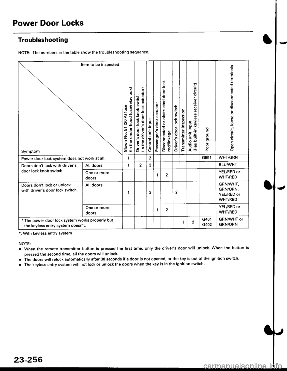
Troubleshooting
NOTE: The numbers in the table show the troubleshooting sequence.
*: With keyless entry system
NOTE:
. When the remote transmitter button is pressed the first time, only the driver's door will unlock. When the button is
pressed the second time, all the doors will unlock.
. Thedoorswill relock a utomatica lly after 30 seconds if a door is not opened, or the key is out ot the ign ition switch.
. The keyless entry system will not lock or unlock the doors when the key is in the ignition switch.
Item to be inspected
Symptom
s
{o
x6
tn6
l5
€5
5O
o:E,
ooo>
o
;
o
>t
6<
o:
3
:o
o
.9
':
E
F
q)
<5
I
E
c
Power door lock svstem does not work at all.1ucc IWHT/GRN
Doors don't lock with driver's
door lock knob switch.
All doorsI2BLU,ryVHT
One or more
doors
YEURED or
WHT/RED
Doors don't lock or unlock
with driver's door lock switch.
All doors
1
GRN/WHT,
GRN/ORN,
YEURED or
WHT/RED
One or more
ooors
YEURED or
WHT/RED
*The power door lock system works properly but
the keyless entry system doesn't.1G401
G402
GRNAVHT or
GRNiORN
23-256