1996 CHRYSLER VOYAGER engine
[x] Cancel search: enginePage 1846 of 1938
(10) Disconnect the two upper mounts from the
upper reinforcement and the lower mount from the
tunnel.
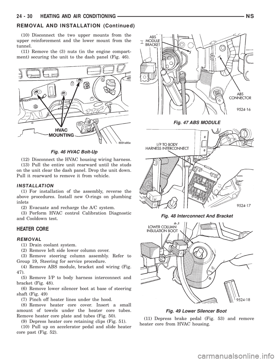
(11) Remove the (3) nuts (in the engine compart-
ment) securing the unit to the dash panel (Fig. 46).
(12) Disconnect the HVAC housing wiring harness.
(13) Pull the entire unit rearward until the studs
on the unit clear the dash panel. Drop the unit down.
Pull it rearward to remove it from vehicle.
INSTALLATION
(1) For installation of the assembly, reverse the
above procedures. Install new O-rings on plumbing
inlets
(2) Evacuate and recharge the A/C system.
(3) Perform HVAC control Calibration Diagnostic
and Cooldown test.
HEATER CORE
REMOVAL
(1) Drain coolant system.
(2) Remove left side lower column cover.
(3) Remove steering column assembly. Refer to
Group 19, Steering for service procedure.
(4) Remove ABS module, bracket and wiring (Fig.
47).
(5) Remove I/P to body harness interconnect and
bracket (Fig. 48).
(6) Remove lower silencer boot at base of steering
shaft (Fig. 49)
(7) Pinch off heater lines under the hood.
(8) Remove heater core cover. Insert a small
amount of towels under the heater core tubes.
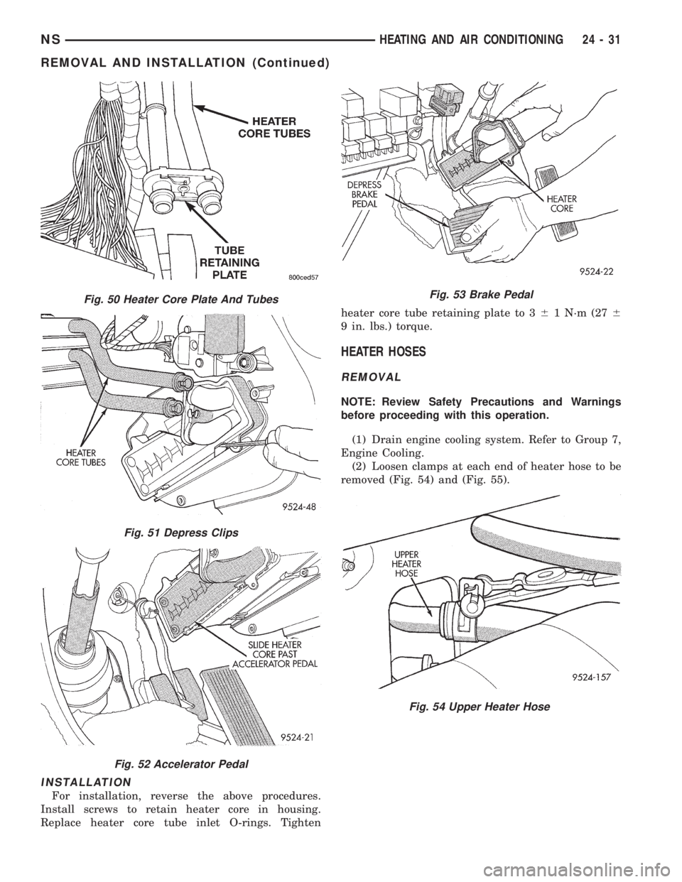
Remove heater core plate and tubes (Fig. 50).
(9) Depress heater core retaining clips (Fig. 51).
(10) Pull up on accelerator pedal and slide heater
core past (Fig. 52).(11) Depress brake pedal (Fig. 53) and remove
heater core from HVAC housing.
Fig. 46 HVAC Bolt-Up
Fig. 47 ABS MODULE
Fig. 48 Interconnect And Bracket
Fig. 49 Lower Silencer Boot
24 - 30 HEATING AND AIR CONDITIONINGNS
REMOVAL AND INSTALLATION (Continued)
Page 1847 of 1938
INSTALLATION
For installation, reverse the above procedures.
Install screws to retain heater core in housing.
Replace heater core tube inlet O-rings. Tightenheater core tube retaining plate to 361 N´m (276
9 in. lbs.) torque.
HEATER HOSES
REMOVAL
NOTE: Review Safety Precautions and Warnings
before proceeding with this operation.
(1) Drain engine cooling system. Refer to Group 7,
Engine Cooling.
(2) Loosen clamps at each end of heater hose to be
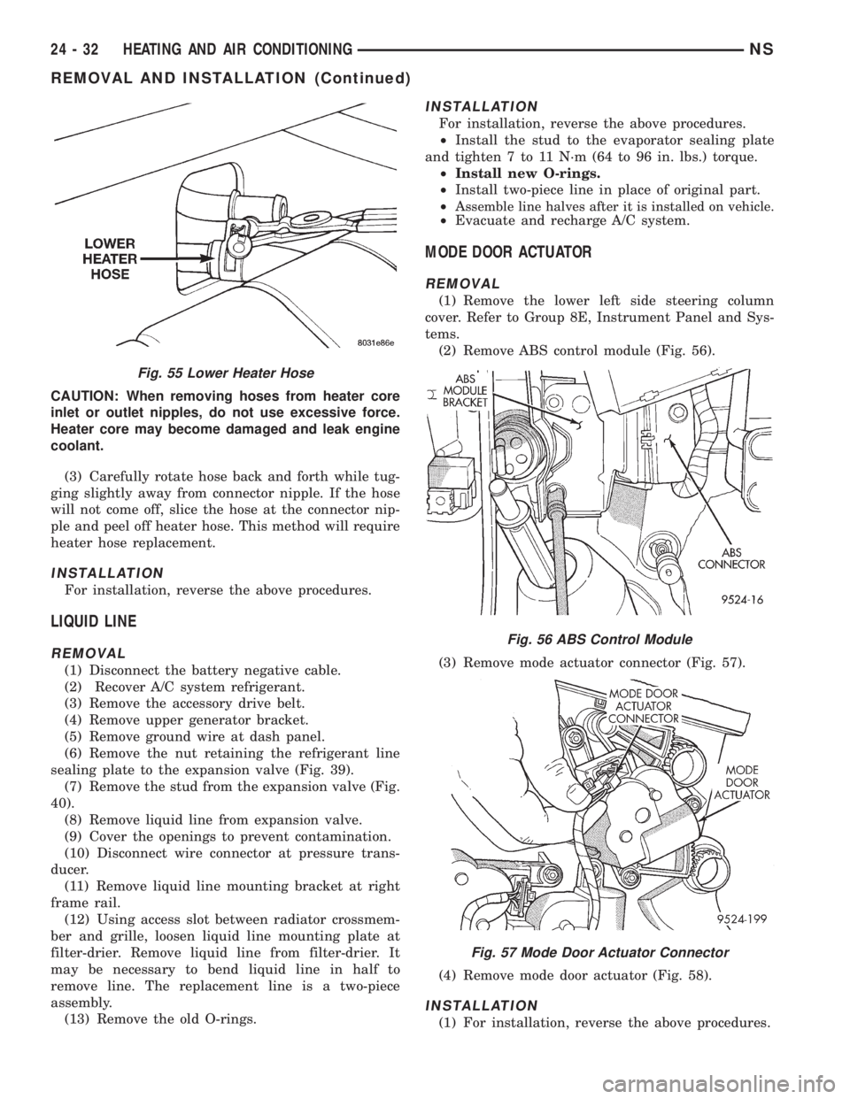
removed (Fig. 54) and (Fig. 55).
Fig. 50 Heater Core Plate And Tubes
Fig. 51 Depress Clips
Fig. 52 Accelerator Pedal
Fig. 53 Brake Pedal
Fig. 54 Upper Heater Hose
NSHEATING AND AIR CONDITIONING 24 - 31
REMOVAL AND INSTALLATION (Continued)
Page 1848 of 1938
CAUTION: When removing hoses from heater core
inlet or outlet nipples, do not use excessive force.
Heater core may become damaged and leak engine
coolant.
(3) Carefully rotate hose back and forth while tug-
ging slightly away from connector nipple. If the hose
will not come off, slice the hose at the connector nip-
ple and peel off heater hose. This method will require
heater hose replacement.
INSTALLATION
For installation, reverse the above procedures.
LIQUID LINE
REMOVAL
(1) Disconnect the battery negative cable.
(2) Recover A/C system refrigerant.
(3) Remove the accessory drive belt.
(4) Remove upper generator bracket.
(5) Remove ground wire at dash panel.
(6) Remove the nut retaining the refrigerant line
sealing plate to the expansion valve (Fig. 39).
(7) Remove the stud from the expansion valve (Fig.
40).
(8) Remove liquid line from expansion valve.
(9) Cover the openings to prevent contamination.
(10) Disconnect wire connector at pressure trans-
ducer.
(11) Remove liquid line mounting bracket at right
frame rail.
(12) Using access slot between radiator crossmem-
ber and grille, loosen liquid line mounting plate at
filter-drier. Remove liquid line from filter-drier. It
may be necessary to bend liquid line in half to
remove line. The replacement line is a two-piece
assembly.
(13) Remove the old O-rings.
INSTALLATION
For installation, reverse the above procedures.
²Install the stud to the evaporator sealing plate
and tighten 7 to 11 N´m (64 to 96 in. lbs.) torque.
²Install new O-rings.
²Install two-piece line in place of original part.
²A
ssemble line halves after it is installed on vehicle.²Evacuate and recharge A/C system.
MODE DOOR ACTUATOR
REMOVAL
(1) Remove the lower left side steering column
cover. Refer to Group 8E, Instrument Panel and Sys-
tems.
(2) Remove ABS control module (Fig. 56).
(3) Remove mode actuator connector (Fig. 57).
(4) Remove mode door actuator (Fig. 58).
INSTALLATION
(1) For installation, reverse the above procedures.
Fig. 55 Lower Heater Hose
Fig. 56 ABS Control Module
Fig. 57 Mode Door Actuator Connector
24 - 32 HEATING AND AIR CONDITIONINGNS
REMOVAL AND INSTALLATION (Continued)
Page 1851 of 1938
CAUTION: Do not damage the insulation barrier
surrounding the evaporator.(9) Carefully pull up on evaporator and remove
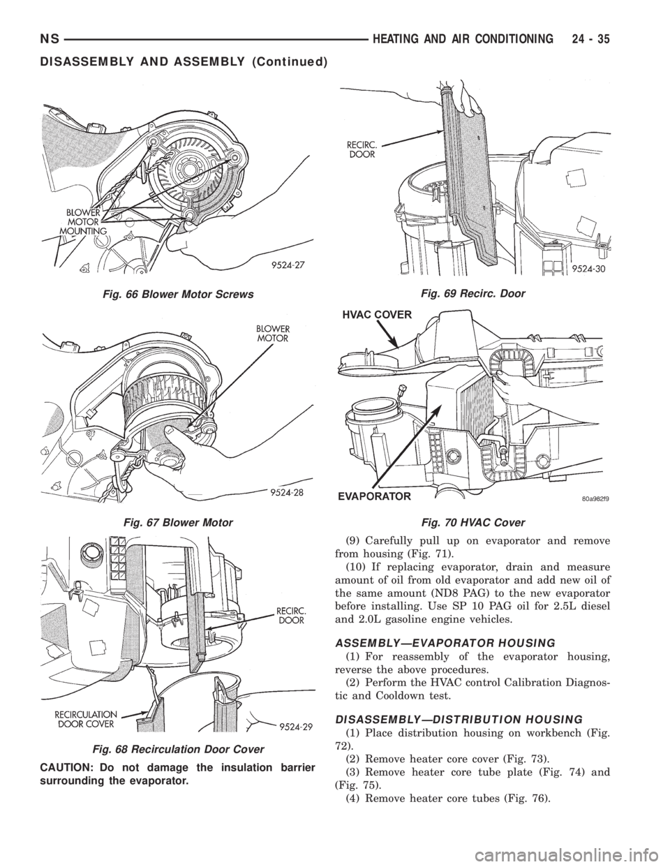
from housing (Fig. 71).
(10) If replacing evaporator, drain and measure
amount of oil from old evaporator and add new oil of
the same amount (ND8 PAG) to the new evaporator
before installing. Use SP 10 PAG oil for 2.5L diesel
and 2.0L gasoline engine vehicles.
ASSEMBLYÐEVAPORATOR HOUSING
(1) For reassembly of the evaporator housing,
reverse the above procedures.
(2) Perform the HVAC control Calibration Diagnos-
tic and Cooldown test.
DISASSEMBLYÐDISTRIBUTION HOUSING
(1) Place distribution housing on workbench (Fig.
72).
(2) Remove heater core cover (Fig. 73).
(3) Remove heater core tube plate (Fig. 74) and
(Fig. 75).
(4) Remove heater core tubes (Fig. 76).
Fig. 66 Blower Motor Screws
Fig. 67 Blower Motor
Fig. 68 Recirculation Door Cover
Fig. 69 Recirc. Door
Fig. 70 HVAC Cover
NSHEATING AND AIR CONDITIONING 24 - 35
DISASSEMBLY AND ASSEMBLY (Continued)
Page 1860 of 1938
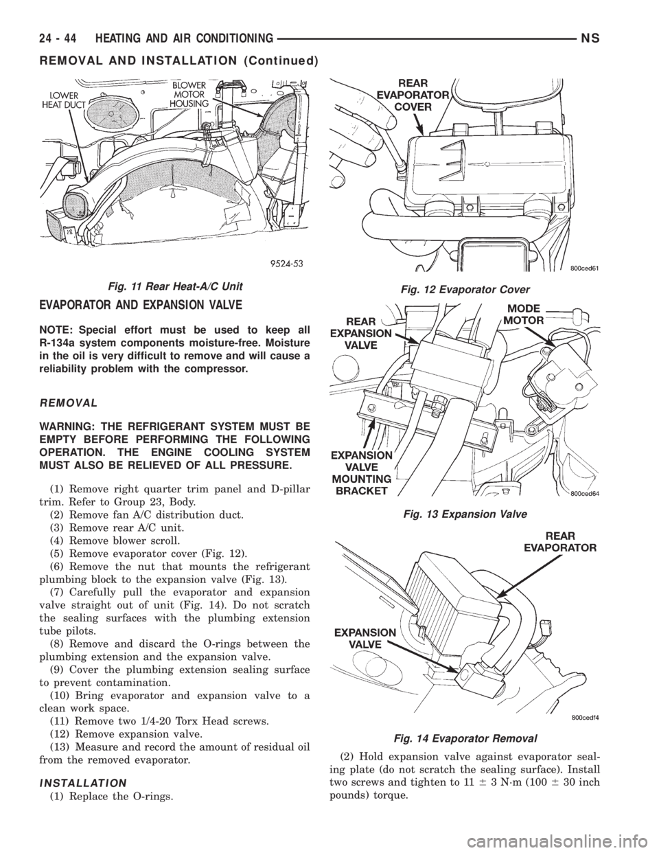
EVAPORATOR AND EXPANSION VALVE
NOTE: Special effort must be used to keep all
R-134a system components moisture-free. Moisture
in the oil is very difficult to remove and will cause a
reliability problem with the compressor.
REMOVAL
WARNING: THE REFRIGERANT SYSTEM MUST BE
EMPTY BEFORE PERFORMING THE FOLLOWING
OPERATION. THE ENGINE COOLING SYSTEM
MUST ALSO BE RELIEVED OF ALL PRESSURE.
(1) Remove right quarter trim panel and D-pillar
trim. Refer to Group 23, Body.
(2) Remove fan A/C distribution duct.
(3) Remove rear A/C unit.
(4) Remove blower scroll.
(5) Remove evaporator cover (Fig. 12).
(6) Remove the nut that mounts the refrigerant
plumbing block to the expansion valve (Fig. 13).
(7) Carefully pull the evaporator and expansion
valve straight out of unit (Fig. 14). Do not scratch
the sealing surfaces with the plumbing extension
tube pilots.
(8) Remove and discard the O-rings between the
plumbing extension and the expansion valve.
(9) Cover the plumbing extension sealing surface
to prevent contamination.
(10) Bring evaporator and expansion valve to a
clean work space.
(11) Remove two 1/4-20 Torx Head screws.
(12) Remove expansion valve.
(13) Measure and record the amount of residual oil
from the removed evaporator.
INSTALLATION
(1) Replace the O-rings.(2) Hold expansion valve against evaporator seal-
ing plate (do not scratch the sealing surface). Install
two screws and tighten to 1163 N´m (100630 inch
pounds) torque.
Fig. 11 Rear Heat-A/C UnitFig. 12 Evaporator Cover
Fig. 13 Expansion Valve
Fig. 14 Evaporator Removal
24 - 44 HEATING AND AIR CONDITIONINGNS
REMOVAL AND INSTALLATION (Continued)
Page 1861 of 1938
CAUTION: Do not damage the evaporator insulation
liner during installation.
(3) Carefully install the evaporator and expansion
valve straight into the unit. Do not scratch the seal-
ing surfaces with the plumbing extension tube pilots.
(4) Determine the amount of old refrigerant oil
drained from the evaporator. Add this amount (of
clean refrigerant oil) back into the system.
(5) Carefully align the expansion valve onto the
pilot tubes of the plumbing extension (do not scratch
the sealing surface). Install the bolt through the
plumbing plate into the unit sealing plate. Tighten
bolts to 2363 N´m (200630 inch pounds) torque.
(6) Install evaporator cover and blower scroll.
(7) Install quarter trim panel, evacuate/charge sys-
tem, and perform the performance test.
REAR AIR CONDITIONING LINES
WARNING: THE REFRIGERATION SYSTEM MUST
BE COMPLETELY EMPTY BEFORE PROCEEDING
WITH THIS OPERATION.
REMOVAL
(1) Hoist vehicle
(2) Remove compression fittings to the suction and
liquid lines located on the right, outboard side of the
underbody, rearward of the front crossmember. (Fig.
2)
(3) remove (1) bolt securing a/c lines to block
located on the right, outboard side of the underbody,
rearward of the rear wheel and tire. (Fig. 5)
(4) Remove (3) straps securing underbody lines.
(Fig. 1)
(5) Separate and remove a/c lines from vehicle.
INSTALLATION
(1) Before installation, replace all O-rings and gas-
kets. Coat all sealing surfaces with approved wax-
free refrigerant oil. Then, reverse the above
procedures.
(2) Evacuate and recharge system.
REAR HEATER A/C AIR OUTLETS
REMOVAL
Separate barrel from bezel by pulling outward.
INSTALLATION
For installation, push the outlet firmly into the
opening until it locks into place.
REAR HEATER-A/C AUXILIARY CONDENSER
If vehicle is equipped with a 3.3L or 3.8L engine
with rear heater and air conditioning, it will be
equipped with an auxiliary condenser. The auxiliarycondenser is mounted on the primary condenser in
front of the radiator. Both condenser must be
removed as an assembly and then separated.
WARNING: THE REFRIGERATION SYSTEM MUST
BE COMPLETELY EMPTY BEFORE PROCEEDING
WITH THIS OPERATION.
NOTE: Special effort must be used to keep all
R-134a system components moisture-free. Moisture
in the oil is very difficult to remove and will cause a
reliability problem with the compressor.
The condenser assembly must first be removed
from vehicle. Refer to CONDENSER ASSEMBLY
removal and installation in this section for service
procedures.
REMOVAL
(1) After condenser assembly removal, place on
bench for disassembly.
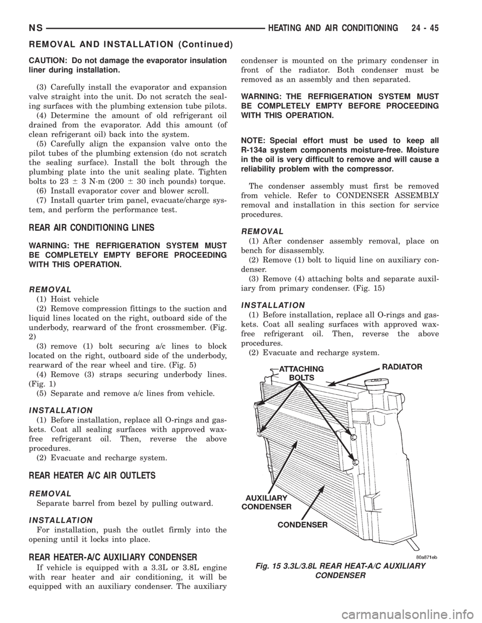
(2) Remove (1) bolt to liquid line on auxiliary con-
denser.
(3) Remove (4) attaching bolts and separate auxil-
iary from primary condenser. (Fig. 15)
INSTALLATION
(1) Before installation, replace all O-rings and gas-
kets. Coat all sealing surfaces with approved wax-
free refrigerant oil. Then, reverse the above
procedures.
(2) Evacuate and recharge system.
Fig. 15 3.3L/3.8L REAR HEAT-A/C AUXILIARY
CONDENSER
NSHEATING AND AIR CONDITIONING 24 - 45
REMOVAL AND INSTALLATION (Continued)
Page 1862 of 1938
REAR HEATER A/C BLOWER MOTOR
REMOVAL
(1) Remove the right quarter trim panel and D-pil-
lar trim. Refer to Group 23, Body for service proce-
dures.
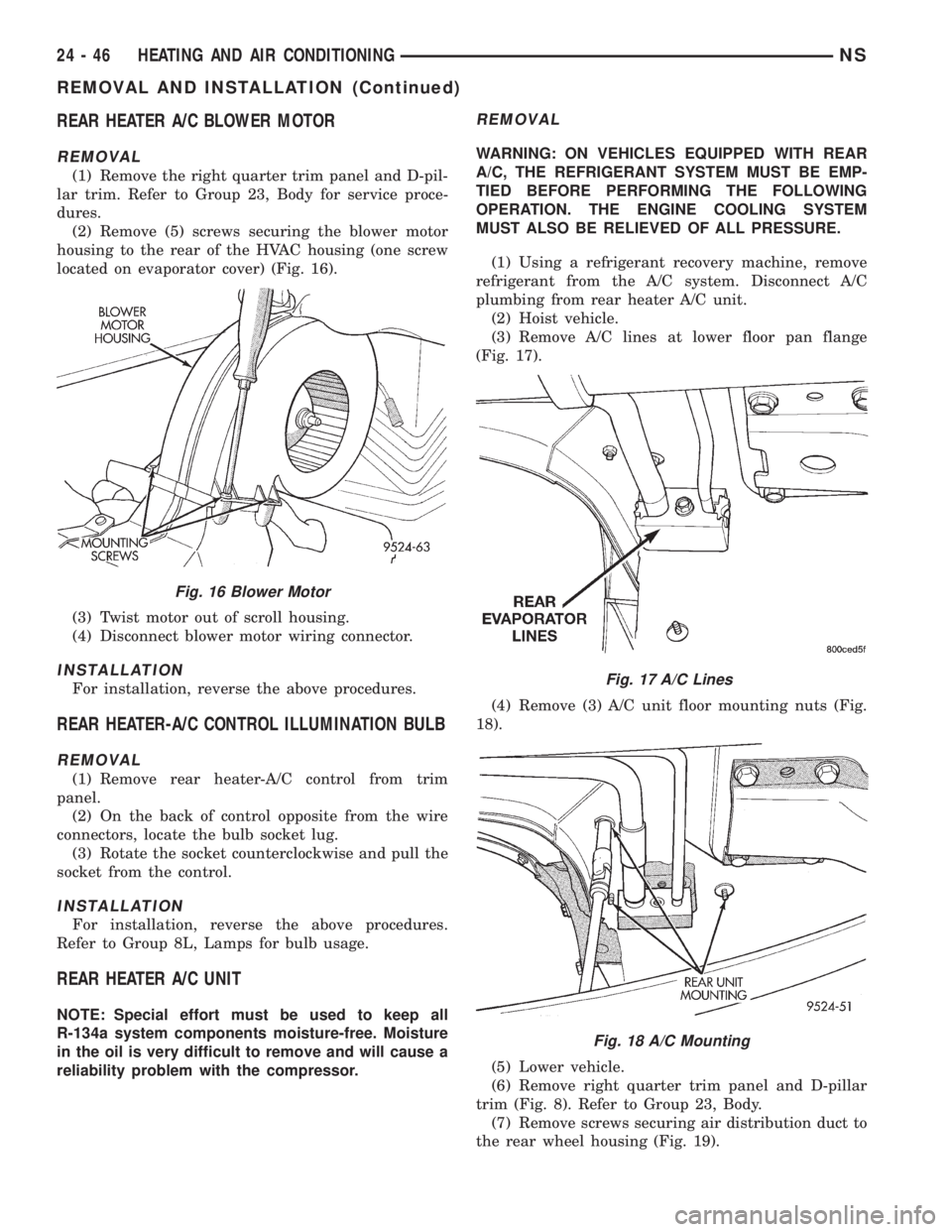
(2) Remove (5) screws securing the blower motor
housing to the rear of the HVAC housing (one screw
located on evaporator cover) (Fig. 16).
(3) Twist motor out of scroll housing.
(4) Disconnect blower motor wiring connector.
INSTALLATION
For installation, reverse the above procedures.
REAR HEATER-A/C CONTROL ILLUMINATION BULB
REMOVAL
(1) Remove rear heater-A/C control from trim
panel.
(2) On the back of control opposite from the wire
connectors, locate the bulb socket lug.
(3) Rotate the socket counterclockwise and pull the
socket from the control.
INSTALLATION
For installation, reverse the above procedures.
Refer to Group 8L, Lamps for bulb usage.
REAR HEATER A/C UNIT
NOTE: Special effort must be used to keep all
R-134a system components moisture-free. Moisture
in the oil is very difficult to remove and will cause a
reliability problem with the compressor.
REMOVAL
WARNING: ON VEHICLES EQUIPPED WITH REAR
A/C, THE REFRIGERANT SYSTEM MUST BE EMP-
TIED BEFORE PERFORMING THE FOLLOWING
OPERATION. THE ENGINE COOLING SYSTEM
MUST ALSO BE RELIEVED OF ALL PRESSURE.
(1) Using a refrigerant recovery machine, remove
refrigerant from the A/C system. Disconnect A/C
plumbing from rear heater A/C unit.
(2) Hoist vehicle.
(3) Remove A/C lines at lower floor pan flange
(Fig. 17).
(4) Remove (3) A/C unit floor mounting nuts (Fig.
18).
(5) Lower vehicle.
(6) Remove right quarter trim panel and D-pillar
trim (Fig. 8). Refer to Group 23, Body.
(7) Remove screws securing air distribution duct to
the rear wheel housing (Fig. 19).
Fig. 16 Blower Motor
Fig. 17 A/C Lines
Fig. 18 A/C Mounting
24 - 46 HEATING AND AIR CONDITIONINGNS
REMOVAL AND INSTALLATION (Continued)
Page 1864 of 1938
NOTE: If the heater core was emptied and was not
prefilled, it is necessary to thermal cycle the vehicle
TWICE. The heater core is positioned higher than
the radiator fill cap. Therefore the heater core will
not gravity fill to level. To thermal cycle the vehicle,
it must be operated till the thermostat opens, then
turned off and allowed to cool. In order to verify
that the auxiliary unit is filled completely, the follow-
ing procedure can be used:
²Vehicle at room temperature.
²Engine is brought up to operating temperature.
²Front unit is OFF, temperature slides are at full
HEAT position.
²Engine is at idle.
²With rear blower motor ON HIGH.
²Discharge air temperature, measured at the
dual register located on the C-pillar base, is between
135É and 145É F.
REAR HEATER CORE
REMOVAL
(1) Remove the lower right quarter trim panel.
Refer to Group 23, Body.
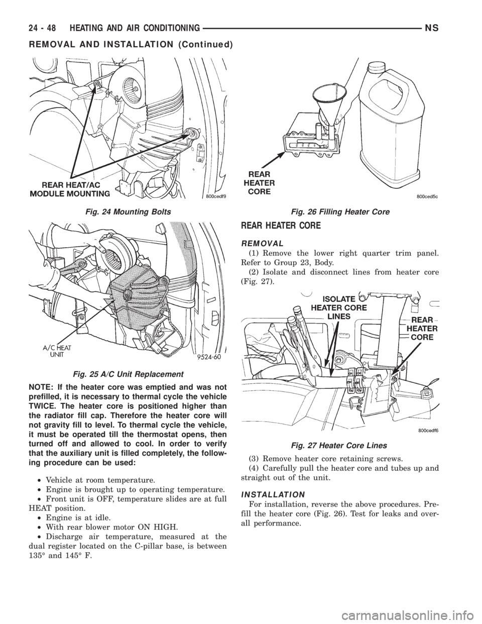
(2) Isolate and disconnect lines from heater core
(Fig. 27).
(3) Remove heater core retaining screws.
(4) Carefully pull the heater core and tubes up and
straight out of the unit.
INSTALLATION
For installation, reverse the above procedures. Pre-
fill the heater core (Fig. 26). Test for leaks and over-
all performance.
Fig. 24 Mounting Bolts
Fig. 25 A/C Unit Replacement
Fig. 26 Filling Heater Core
Fig. 27 Heater Core Lines
24 - 48 HEATING AND AIR CONDITIONINGNS
REMOVAL AND INSTALLATION (Continued)