1996 CHRYSLER VOYAGER engine
[x] Cancel search: enginePage 1688 of 1938
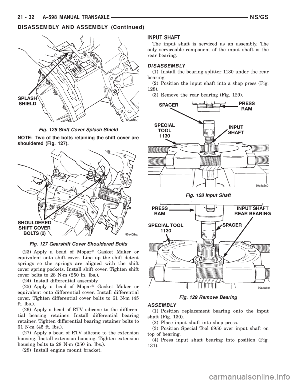
NOTE: Two of the bolts retaining the shift cover are
shouldered (Fig. 127).
(23) Apply a bead of MopartGasket Maker or
equivalent onto shift cover. Line up the shift detent
springs so the springs are aligned with the shift
cover spring pockets. Install shift cover. Tighten shift
cover bolts to 28 N´m (250 in. lbs.).
(24) Install differential assembly.
(25) Apply a bead of MopartGasket Maker or
equivalent onto differential cover. Install differential
cover. Tighten differential cover bolts to 61 N´m (45
ft. lbs.).
(26) Apply a bead of RTV silicone to the differen-
tial bearing retainer. Install differential bearing
retainer. Tighten differential bearing retainer bolts to
61 N´m (45 ft. lbs.).
(27) Apply a bead of RTV silicone to the extension
housing. Install extension housing. Tighten extension
housing bolts to 28 N´m (250 in. lbs.).
(28) Install engine mount bracket.
INPUT SHAFT
The input shaft is serviced as an assembly. The
only serviceable component of the input shaft is the
rear bearing.
DISASSEMBLY
(1) Install the bearing splitter 1130 under the rear
bearing.
(2) Position the input shaft into a shop press (Fig.
128).
(3) Remove the rear bearing (Fig. 129).
ASSEMBLY
(1) Position replacement bearing onto the input
shaft (Fig. 130).
(2) Place input shaft into shop press.
(3) Position Special Tool 6950 over input shaft on
top of bearing.
(4) Press input shaft bearing into position (Fig.
131).
Fig. 126 Shift Cover Splash Shield
Fig. 127 Gearshift Cover Shouldered Bolts
Fig. 128 Input Shaft
Fig. 129 Remove Bearing
21 - 32 A±598 MANUAL TRANSAXLENS/GS
DISASSEMBLY AND ASSEMBLY (Continued)
Page 1716 of 1938
SPECIAL TOOLS
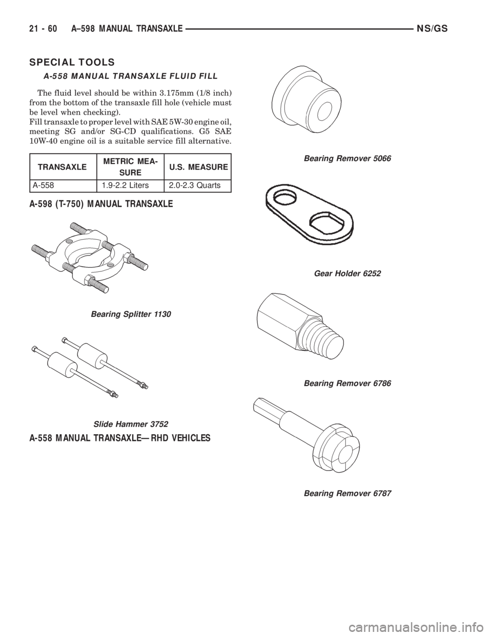
A-598 (T-750) MANUAL TRANSAXLE
A-558 MANUAL TRANSAXLEÐRHD VEHICLES
A-558 MANUAL TRANSAXLE FLUID FILL
The fluid level should be within 3.175mm (1/8 inch)
from the bottom of the transaxle fill hole (vehicle must
be level when checking).
Fill transaxle to proper level with SAE 5W-30 engine oil,
meeting SG and/or SG-CD qualifications. G5 SAE
10W-40 engine oil is a suitable service fill alternative.
TRANSAXLEMETRIC MEA-
SUREU.S. MEASURE
A-558 1.9-2.2 Liters 2.0-2.3 Quarts
Bearing Splitter 1130
Slide Hammer 3752
Bearing Remover 5066
Gear Holder 6252
Bearing Remover 6786
Bearing Remover 6787
21 - 60 A±598 MANUAL TRANSAXLENS/GS
Page 1719 of 1938

TIRES AND WHEELS
CONTENTS
page page
TIRES.................................. 1WHEELS................................ 9
TIRES
INDEX
page page
DESCRIPTION AND OPERATION
RADIAL-PLY TIRES....................... 2
REPLACEMENT TIRES.................... 3
SPARE TIRE (TEMPORARY)................ 2
TIRE INFLATION PRESSURES.............. 2
TIRE INFORMATION...................... 1
TIRE PRESSURE FOR HIGH-SPEED DRIVING . . 3
DIAGNOSIS AND TESTING
LEAD CORRECTION CHART................ 4
PRESSURE GAUGES..................... 3
TIRE NOISE OR VIBRATION................ 4TIRE WEAR PATTERNS.................... 4
TREAD WEAR INDICATORS................ 3
SERVICE PROCEDURES
REPAIRING TIRE LEAKS................... 6
TIRE AND WHEEL MATCH MOUNTING........ 6
TIRE AND WHEEL ROTATION (NON-
DIRECTIONAL THREAD PATTERN).......... 6
CLEANING AND INSPECTION
CLEANING TIRES........................ 7
SPECIFICATIONS
TIRE SPECIFICATIONS.................... 8
DESCRIPTION AND OPERATION
TIRE INFORMATION
Tires are designed and engineered for each specific
vehicle. They provide the best overall performance
for normal operation. The ride and handling charac-
teristics match the vehicle's requirements. With
proper care they will give excellent reliability, trac-
tion, skid resistance, and tread life.
Driving habits have more effect on tire life than
any other factor. Careful drivers will obtain, in most
cases, much greater mileage than severe use or care-
less drivers. A few of the driving habits which will
shorten the life of any tire are:
²Rapid acceleration
²Severe application of brakes
²High-speed driving
²Taking turns at excessive speeds
²Striking curbs and other obstacles
Radial ply tires are more prone to irregular tread
wear. It is important to follow the tire rotation inter-
val shown in the section on Tire Rotation. This will
help to achieve a greater tread-life potential.
TIRE IDENTIFICATION
Tire type, size, aspect ratio and speed rating are
encoded in the letters and numbers imprinted on the
side wall of the tire. Refer to the chart to decipher
the tire identification code (Fig. 1).
Performance tires will have a speed rating letter
after the aspect ratio number. The speed rating is not
always printed on the tire sidewall. The letterSindi-
cates that the tire is speed rated up to 112 mph.
²Qup to 100 mph
²Tup to 118 mph
²Uup to 124 mph
²Hup to 130 mph
²Vup to 149 mph
²Zmore than 149 mph (consult the tire manu-
facturer for the specific speed rating)
An All Season type tire will have eitherM+S,M
&SorM±S(indicating mud and snow traction)
imprinted on the side wall.
TIRE CHAINS
This vehicle was designed to allow the use of a
specified type of snow chain on the tires. Only com-
pact snow chains or other traction aidsmeeting SAE
type ªClass Sº specifications may be used.Any style
NSTIRES AND WHEELS 22 - 1
Page 1722 of 1938

TIRE WEAR PATTERNS
Under inflation will cause wear on the shoulders of
tire. Over inflation will cause wear at the center of
tire.
Excessive camber causes the tire to run at an
angle to the road. One side of tread is then worn
more than the other (Fig. 5).
Excessive toe-in or toe-out causes wear on the
tread edges and a feathered effect across the tread
(Fig. 5).
TIRE NOISE OR VIBRATION
Radial-ply tires are sensitive to force impulses
caused by improper mounting, vibration, wheel
defects, or possibly tire imbalance.To find out if tires are causing the noise or vibra-
tion, drive the vehicle over a smooth road at varying
speeds. Note the noise level during acceleration and
deceleration. The engine, differential and exhaust
noises will change as speed varies, while the tire
noise will usually remain constant.
LEAD CORRECTION CHART
Use the following chart to correct a vehicle leading
or drifting problem.
Fig. 5 Tire Wear Patterns
22 - 4 TIRES AND WHEELSNS
DIAGNOSIS AND TESTING (Continued)
Page 1732 of 1938
PAINT
INDEX
page page
GENERAL INFORMATION
AFTERMARKET PAINT REPAIR PRODUCTS.... 3
BASE COAT/CLEAR COAT FINISH............ 2PAINT CODE............................ 2
PAINTED SURFACE TOUCH-UP............. 2
WET SANDING, BUFFING, AND POLISHING.... 2
GENERAL INFORMATION
PAINT CODE
A paint code is provided on the body code plate
located in the engine compartment. Refer to the
Introduction section at the front of this manual for
body code plate description. The paint and trim codes
are also included on the Vehicle Safety Label located
on the driver's door end frame.
BASE COAT/CLEAR COAT FINISH
On most vehicles a two-part paint application (base
coat/clear coat) is used. Color paint that is applied to
primer is called base coat. The clear coat protects the
base coat from ultraviolet light and provides a dura-
ble high-gloss finish.
WET SANDING, BUFFING, AND POLISHING
Minor acid etching, orange peel, or smudging in
clear coat or single-stage finishes can be reduced
with light wet sanding, hand buffing, and polishing.
If the finish has been wet sanded in the past, it
cannot be repeated. Wet sanding operation
should be performed by a trained automotive
paint technician.
CAUTION: Do not remove clear coat finish, if
equipped. Base coat paint must retain clear coat for
durability.
PAINTED SURFACE TOUCH-UP
When a painted metal surface has been scratched
or chipped, it should be touched-up as soon as possi-
ble to avoid corrosion. For best results, use Mopart
Scratch Filler/Primer, Touch-Up Paints and Clear Top
Coat. Refer to Introduction group of this manual for
Body Code Plate information.
TOUCH-UP PROCEDURE
(1) Scrape loose paint and corrosion from inside
scratch or chip.
(2) Clean affected area with MopartTar/Road Oil
Remover, and allow to dry.
(3) Fill the inside of the scratch or chip with a coat
of filler/primer. Do not overlap primer onto good sur-
face finish. The applicator brush should be wet
enough to puddle-fill the defect without running. Do
not stroke brush applicator on body surface. Allow
the filler/primer to dry hard.
(4) Cover the filler/primer with color touch-up
paint. Do not overlap touch-up color onto the original
color coat around the scratch or chip. Butt the new
color to the original color, if possible. Do not stroke
applicator brush on body surface. Allow touch-up
paint to dry hard.
(5) On vehicles without clear coat, the touch-up
color can be lightly wet sanded (1500 grit) and pol-
ished with rubbing compound.
(6) On vehicles with clear coat, apply clear top coat
to touch-up paint with the same technique as
described in Step 4. Allow clear top coat to dry hard.
If desired, Step 5 can be performed on clear top coat.
23 - 2 BODYNS
Page 1754 of 1938
Some water leaks must be tested for a considerable
length of time to become apparent. When a leak
appears, find the highest point of the water track or
drop. The highest point usually will show the point of
entry. After leak point has been found, repair the
leak and water test to verify that the leak has
stopped.
Locating the entry point of water that is leaking
into a cavity between panels can be difficult. The
trapped water may splash or run from the cavity,
often at a distance from the entry point. Most water
leaks of this type become apparent after accelerating,
stopping, turning, or when on an incline.
MIRROR INSPECTION METHOD
When a leak point area is visually obstructed, use
a suitable mirror to gain visual access. A mirror can
also be used to deflect light to a limited-access area
to assist in locating a leak point.
BRIGHT LIGHT LEAK TEST METHOD
Some water leaks in the luggage compartment can
be detected without water testing. Position the vehi-
cle in a brightly lit area. From inside the darkened
luggage compartment inspect around seals and body
seams. If necessary, have a helper direct a drop light
over the suspected leak areas around the luggage
compartment. If light is visible through a normally
sealed location, water could enter through the open-
ing.
PRESSURIZED LEAK TEST METHOD
When a water leak into the passenger compart-
ment cannot be detected by water testing, pressurize
the passenger compartment and soap test exterior of
the vehicle. To pressurize the passenger compart-
ment, close all doors and windows, start engine, and
set heater control to high blower in HEAT position. If
engine can not be started, connect a charger to the
battery to ensure adequate voltage to the blower.
With interior pressurized, apply dish detergent solu-
tion to suspected leak area on the exterior of the
vehicle. Apply detergent solution with spray device or
soft bristle brush. If soap bubbles occur at a body
seam, joint, seal or gasket, the leak entry point could
be at that location.
WIND NOISE
Wind noise is the result of most air leaks. Air leaks
can be caused by poor sealing, improper body compo-
nent alignment, body seam porosity, or missing plugs
in the engine compartment or door hinge pillar areas.
All body sealing points should be airtight in normal
driving conditions. Moving sealing surfaces will not
always seal airtight under all conditions. At times,
side glass or door seals will allow wind noise to be
noticed in the passenger compartment during highcrosswinds. Over compensating on door or glass
adjustments to stop wind noise that occurs under
severe conditions can cause premature seal wear and
excessive closing or latching effort. After a repair pro-
cedure has been performed, test vehicle to verify
noise has stopped before returning vehicle to use.
Wind noise can also be caused by improperly fitted
exterior moldings or body ornamentation. Loose
moldings can flutter, creating a buzzing or chattering
noise. An open cavity or protruding edge can create a
whistling or howling noise. Inspect the exterior of the
vehicle to verify that these conditions do not exist.
VISUAL INSPECTION BEFORE TESTS
Verify that floor and body plugs are in place and
body components are aligned and sealed. If component
alignment or sealing is necessary, refer to the appro-
priate section of this group for proper procedures.
ROAD TESTING WIND NOISE
(1) Drive the vehicle to verify the general location
of the wind noise.
(2) Apply 50 mm (2 in.) masking tape in 150 mm
(6 in.) lengths along weatherstrips, weld seams or
moldings. After each length is applied, drive the vehi-
cle. If noise goes away after a piece of tape is applied,
remove tape, locate, and repair defect.
POSSIBLE CAUSE OF WIND NOISE
²Moldings standing away from body surface can
catch wind and whistle.
²Gaps in sealed areas behind overhanging body
flanges can cause wind-rushing sounds.
²Misaligned movable components.
²Missing or improperly installed plugs in pillars.
²Weld burn through holes.
SERVICE PROCEDURES
HEAT STAKING
(1) Remove trim panel.
(2) Bend or move the trim panel components at
the heat staked joints. Observe the heat staked loca-
tions and/or component seams for looseness.
(3) Heat stake the components.
(a) If the heat staked or component seam loca-
tion is loose, hold the two components tightly
together and using a soldering gun with a flat tip,
melt the material securing the components
together. Do not over heat the affected area, dam-
age to the exterior of the trim panel may occur.
(b) If the heat staked material is broken or miss-
ing, use a hot glue gun to apply new material to
the area to be repaired. The panels that are being
heat staked must be held together while the apply-
ing the glue. Once the new material is in place, it
23 - 24 BODYNS
DIAGNOSIS AND TESTING (Continued)
Page 1772 of 1938
(7) Tighten attaching bolts to 11 to 16 N´m (100 to
140 in. lbs.) torque.
HOOD LATCH STRIKER
REMOVAL
(1) Release hood latch and open hood.
(2) Remove bolts holding striker to inside of hood
(Fig. 44).
(3) Remove hood latch striker from vehicle.
INSTALLATION
(1) Position hood latch striker on vehicle.
(2) Install bolts to hold hood latch striker to hood.
(3) Align hood latch striker to engage smoothly
into hood latch.
(4) Verify hood operation and alignment. Adjust as
necessary.
(5) Tighten attaching bolts to 11 to 16 N´m (100 to
140 in. lbs.) torque.
HOOD RELEASE CABLE
REMOVAL
(1) Remove hood latch.
(2) Disengage cable end from hood latch locking
mechanism.
(3) Slide cable case end sideways in keyhole slot of
hood latch while pinching barb on cable case closed.
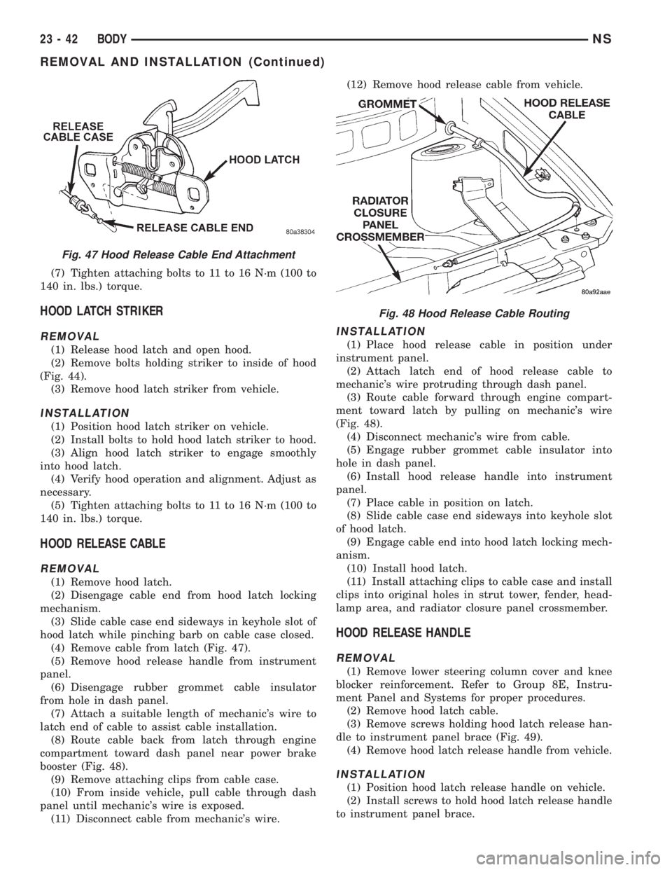
(4) Remove cable from latch (Fig. 47).
(5) Remove hood release handle from instrument
panel.
(6) Disengage rubber grommet cable insulator
from hole in dash panel.
(7) Attach a suitable length of mechanic's wire to
latch end of cable to assist cable installation.
(8) Route cable back from latch through engine
compartment toward dash panel near power brake
booster (Fig. 48).
(9) Remove attaching clips from cable case.
(10) From inside vehicle, pull cable through dash
panel until mechanic's wire is exposed.
(11) Disconnect cable from mechanic's wire.(12) Remove hood release cable from vehicle.
INSTALLATION
(1) Place hood release cable in position under
instrument panel.
(2) Attach latch end of hood release cable to
mechanic's wire protruding through dash panel.
(3) Route cable forward through engine compart-
ment toward latch by pulling on mechanic's wire
(Fig. 48).
(4) Disconnect mechanic's wire from cable.
(5) Engage rubber grommet cable insulator into
hole in dash panel.
(6) Install hood release handle into instrument
panel.
(7) Place cable in position on latch.
(8) Slide cable case end sideways into keyhole slot
of hood latch.
(9) Engage cable end into hood latch locking mech-
anism.
(10) Install hood latch.
(11) Install attaching clips to cable case and install
clips into original holes in strut tower, fender, head-
lamp area, and radiator closure panel crossmember.
HOOD RELEASE HANDLE
REMOVAL
(1) Remove lower steering column cover and knee
blocker reinforcement. Refer to Group 8E, Instru-
ment Panel and Systems for proper procedures.
(2) Remove hood latch cable.
(3) Remove screws holding hood latch release han-
dle to instrument panel brace (Fig. 49).
(4) Remove hood latch release handle from vehicle.
INSTALLATION
(1) Position hood latch release handle on vehicle.
(2) Install screws to hold hood latch release handle
to instrument panel brace.
Fig. 47 Hood Release Cable End Attachment
Fig. 48 Hood Release Cable Routing
23 - 42 BODYNS
REMOVAL AND INSTALLATION (Continued)
Page 1783 of 1938
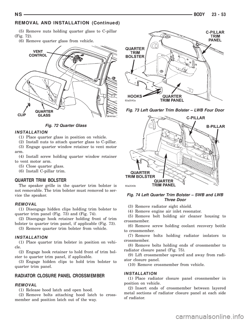
(5) Remove nuts holding quarter glass to C-pillar
(Fig. 72).
(6) Remove quarter glass from vehicle.
INSTALLATION
(1) Place quarter glass in position on vehicle.
(2) Install nuts to attach quarter glass to C-pillar.
(3) Engage quarter window retainer to vent motor
arm.
(4) Install screw holding quarter window retainer
to vent motor arm.
(5) Close quarter glass.
(6) Install C-pillar trim.
QUARTER TRIM BOLSTER
The speaker grille in the quarter trim bolster is
not removable. The trim bolster must removed to ser-
vice the speaker.
REMOVAL
(1) Disengage hidden clips holding trim bolster to
quarter trim panel (Fig. 73) and (Fig. 74).
(2) Disengage hook retainer holding front of trim
bolster to quarter trim panel, if applicable (Fig. 73).
(3) Remove quarter trim bolster from vehicle.
INSTALLATION
(1) Place quarter trim bolster in position on vehi-
cle.
(2) Engage hook retainer to hold front of trim bol-
ster to quarter trim panel, if applicable.
(3) Engage hidden clips to hold trim bolster to
quarter trim panel.
RADIATOR CLOSURE PANEL CROSSMEMBER
REMOVAL
(1) Release hood latch and open hood.
(2) Remove bolts attaching hood latch to cross-
member and position latch out of the way.(3) Remove radiator sight shield.
(4) Remove engine air inlet resonator.
(5) Remove bolt holding air cleaner housing to
crossmember.
(6) Remove screw holding coolant recovery bottle
to crossmember.
(7) Remove bolts holding radiator isolators to
crossmember.
(8) Remove bolts holding ends of crossmember to
radiator closure panel (Fig. 75).
(9) Lift crossmember upward and away from radi-
ator closure panel.
(10) Remove crossmember from vehicle.
INSTALLATION
(1) Place radiator closure panel crossmember in
position on vehicle.
(2) Insert ends of crossmember between layered
metal sections of radiator closure panel at each side
of radiator.
Fig. 72 Quarter Glass
Fig. 73 Left Quarter Trim Bolster ± LWB Four Door
Fig. 74 Left Quarter Trim Bolster ± SWB and LWB
Three Door
NSBODY 23 - 53
REMOVAL AND INSTALLATION (Continued)