1996 CHRYSLER VOYAGER engine
[x] Cancel search: enginePage 1641 of 1938
FLUID LEAK DIAGNOSIS
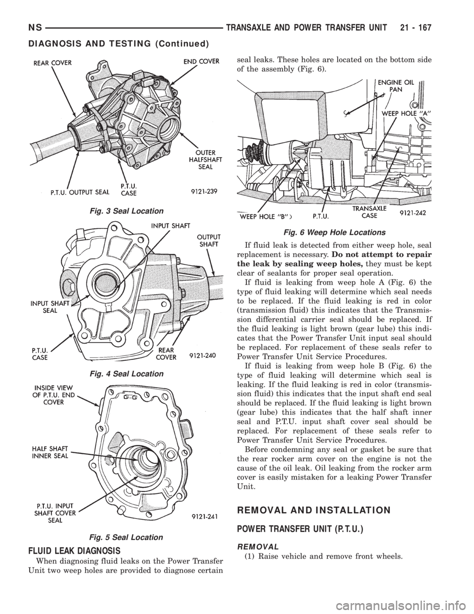
When diagnosing fluid leaks on the Power Transfer
Unit two weep holes are provided to diagnose certainseal leaks. These holes are located on the bottom side
of the assembly (Fig. 6).
If fluid leak is detected from either weep hole, seal
replacement is necessary.Do not attempt to repair
the leak by sealing weep holes,they must be kept
clear of sealants for proper seal operation.
If fluid is leaking from weep hole A (Fig. 6) the
type of fluid leaking will determine which seal needs
to be replaced. If the fluid leaking is red in color
(transmission fluid) this indicates that the Transmis-
sion differential carrier seal should be replaced. If
the fluid leaking is light brown (gear lube) this indi-
cates that the Power Transfer Unit input seal should
be replaced. For replacement of these seals refer to
Power Transfer Unit Service Procedures.
If fluid is leaking from weep hole B (Fig. 6) the
type of fluid leaking will determine which seal is
leaking. If the fluid leaking is red in color (transmis-
sion fluid) this indicates that the input shaft end seal
should be replaced. If the fluid leaking is light brown
(gear lube) this indicates that the half shaft inner
seal and P.T.U. input shaft cover seal should be
replaced. For replacement of these seals refer to
Power Transfer Unit Service Procedures.
Before condemning any seal or gasket be sure that
the rear rocker arm cover on the engine is not the
cause of the oil leak. Oil leaking from the rocker arm
cover is easily mistaken for a leaking Power Transfer
Unit.
REMOVAL AND INSTALLATION
POWER TRANSFER UNIT (P.T.U.)
REMOVAL
(1) Raise vehicle and remove front wheels.
Fig. 3 Seal Location
Fig. 4 Seal Location
Fig. 5 Seal Location
Fig. 6 Weep Hole Locations
NSTRANSAXLE AND POWER TRANSFER UNIT 21 - 167
DIAGNOSIS AND TESTING (Continued)
Page 1658 of 1938
GENERAL INFORMATION
A-598 MANUAL TRANSAXLE
Safety goggles should be worn at all times
when working on these transaxles.The A-598
manual transaxle uses SAE 5W-30 engine oil, meet-
ing SG and/or SG-CD qualifications, as the factory
fill lubricant. SAE G5 10W-40 engine oil is a suitable
service fill alternative.
This transaxle combines gear reduction, ratio selec-
tion, and differential functions in one unit. It is
housed in a die-cast aluminum case.
A-558 MANUAL TRANSAXLEÐRHD VEHICLES
Safety goggles should be worn at all times
when working on these transaxles.The A-558
manual transaxle uses SAE 5W-30 engine oil, meet-
ing SG and/or SG-CD qualifications, as the factory
fill lubricant. SAE G5 10W-40 engine oil is a suitable
service fill alternative.
This transaxle combines gear reduction, ratio selec-
tion, and differential functions in one unit. It is
housed in a die-cast aluminum case.
TRANSAXLE IDENTIFICATION INFORMATION
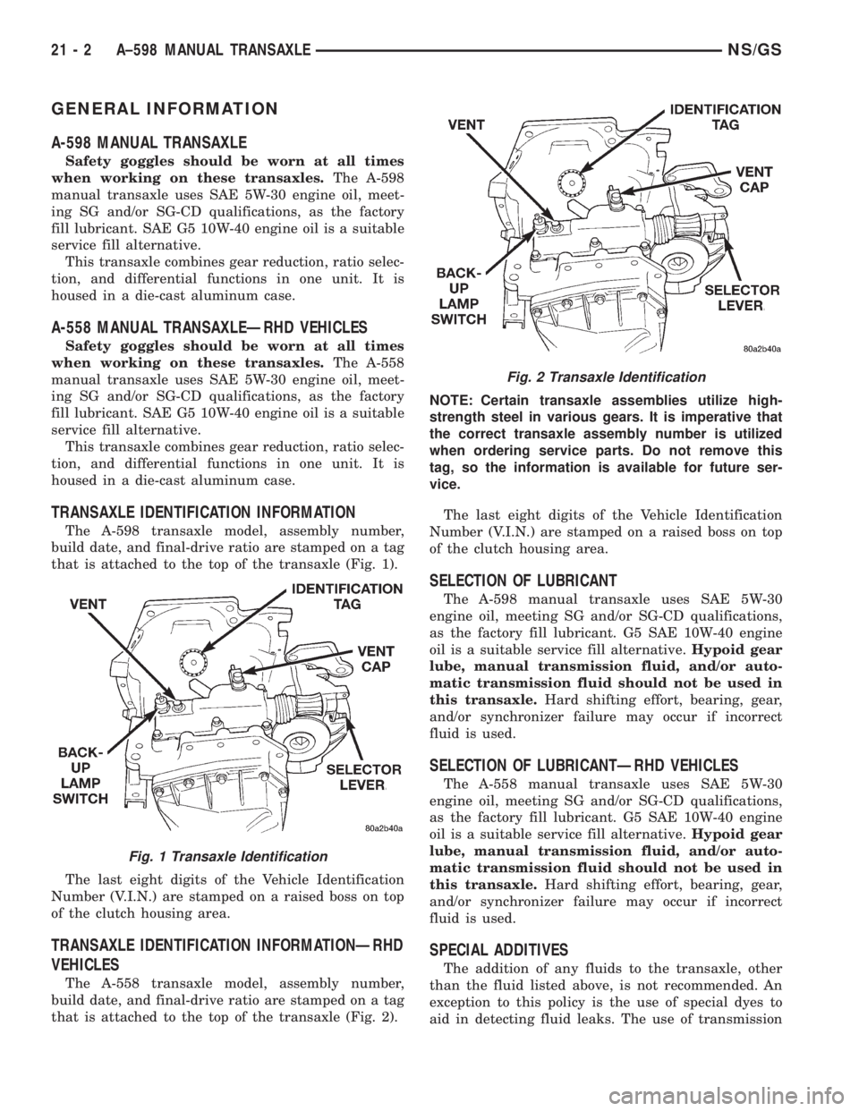
The A-598 transaxle model, assembly number,
build date, and final-drive ratio are stamped on a tag
that is attached to the top of the transaxle (Fig. 1).
The last eight digits of the Vehicle Identification
Number (V.I.N.) are stamped on a raised boss on top
of the clutch housing area.
TRANSAXLE IDENTIFICATION INFORMATIONÐRHD
VEHICLES
The A-558 transaxle model, assembly number,
build date, and final-drive ratio are stamped on a tag
that is attached to the top of the transaxle (Fig. 2).NOTE: Certain transaxle assemblies utilize high-
strength steel in various gears. It is imperative that
the correct transaxle assembly number is utilized
when ordering service parts. Do not remove this
tag, so the information is available for future ser-
vice.
The last eight digits of the Vehicle Identification
Number (V.I.N.) are stamped on a raised boss on top
of the clutch housing area.
SELECTION OF LUBRICANT
The A-598 manual transaxle uses SAE 5W-30
engine oil, meeting SG and/or SG-CD qualifications,
as the factory fill lubricant. G5 SAE 10W-40 engine
oil is a suitable service fill alternative.Hypoid gear
lube, manual transmission fluid, and/or auto-
matic transmission fluid should not be used in
this transaxle.Hard shifting effort, bearing, gear,
and/or synchronizer failure may occur if incorrect
fluid is used.
SELECTION OF LUBRICANTÐRHD VEHICLES
The A-558 manual transaxle uses SAE 5W-30
engine oil, meeting SG and/or SG-CD qualifications,
as the factory fill lubricant. G5 SAE 10W-40 engine
oil is a suitable service fill alternative.Hypoid gear
lube, manual transmission fluid, and/or auto-
matic transmission fluid should not be used in
this transaxle.Hard shifting effort, bearing, gear,
and/or synchronizer failure may occur if incorrect
fluid is used.
SPECIAL ADDITIVES
The addition of any fluids to the transaxle, other
than the fluid listed above, is not recommended. An
exception to this policy is the use of special dyes to
aid in detecting fluid leaks. The use of transmission
Fig. 1 Transaxle Identification
Fig. 2 Transaxle Identification
21 - 2 A±598 MANUAL TRANSAXLENS/GS
Page 1659 of 1938
sealers should be avoided, since they may adversely
affect seals.
SPECIAL ADDITIVESÐRHD VEHICLES
The addition of any fluids to the transaxle, other
than the fluid listed above, is not recommended. An
exception to this policy is the use of special dyes to
aid in detecting fluid leaks. The use of transmission
sealers should be avoided, since they may adversely
affect seals.
GEAR RATIOS
Gear ratios for the 2.4L gasoline engine and 2.5L
Turbo Diesel MTX are as follows:
²1stÐ3.36
²2ndÐ1.90
²3rdÐ1.28
²4thÐ0.92
²5thÐ0.71
²ReverseÐ3.17
Final drive ratio of 3.88 was selected for maximum
performance. All forward gears are synchronized.
Gear ratios for the 2.0L GAS MTX are as follows:
²1stÐ3.69
²2ndÐ2.24
²3rdÐ1.45
²4thÐ1.03
²5thÐ0.81
²ReverseÐ3.17
Final drive ratio of 4.08 was selected for maximum
performance. All forward gears are synchronized.
GEAR RATIOSÐRHD VEHICLES
Gear ratios for the 2.0L GAS MTX are as follows:
²1stÐ3.69
²2ndÐ2.24
²3rdÐ1.45
²4thÐ0.1.03
²5thÐ0.81
²ReverseÐ3.17
Final drive ratio of 4.08 was selected for maximum
performance. All forward gears are synchronized.
GEARSHIFT PATTERN
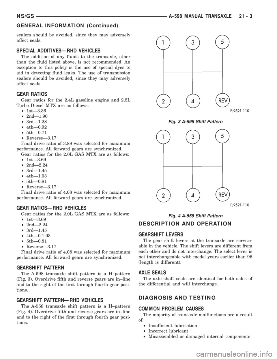
The A-598 transaxle shift pattern is a H±pattern
(Fig. 3). Overdrive fifth and reverse gears are in±line
and to the right of the first through fourth gear posi-
tions.
GEARSHIFT PATTERNÐRHD VEHICLES
The A-558 transaxle shift pattern is a H±pattern
(Fig. 4). Overdrive fifth and reverse gears are in±line
and to the right of the first through fourth gear posi-
tions.
DESCRIPTION AND OPERATION
GEARSHIFT LEVERS
The gear shift levers at the transaxle are service-
able in the vehicle. The shift levers are different from
each other and do not interchange. The select lever is
not interchangeable with model years earlier than 96
(length is different).
AXLE SEALS
The axle shaft seals are identical for both sides of
the differential and will interchange.
DIAGNOSIS AND TESTING
COMMON PROBLEM CAUSES
The majority of transaxle malfunctions are a result
of:
²Insufficient lubrication
²Incorrect lubricant
²Misassembled or damaged internal components
Fig. 3 A-598 Shift Pattern
Fig. 4 A-558 Shift Pattern
NS/GSA±598 MANUAL TRANSAXLE 21 - 3
GENERAL INFORMATION (Continued)
Page 1660 of 1938
²Improper operation
HARD SHIFTING
Hard shifting may be caused by a misadjusted
crossover cable. If hard shifting is accompanied by
gear clash, synchronizer clutch and stop rings or gear
teeth may be worn or damaged.
Misassembled synchronizer components also cause
shifting problems. Incorrectly installed synchronizer
sleeves, struts, or springs can cause shift problems.
NOISY OPERATION
Transaxle noise is most often a result of worn or
damaged components. Chipped, broken gear or syn-
chronizer teeth, and brinnelled, spalled bearings all
cause noise.
Abnormal wear and damage to the internal compo-
nents is frequently the end result of insufficient
lubricant.
SLIPS OUT OF GEAR
Transaxle disengagement may be caused by mis-
aligned or damaged shift components, or worn teeth
on the drive gears or synchronizer components. Incor-
rect assembly also causes gear disengagement.
LOW LUBRICANT LEVEL
Insufficient transaxle lubricant is usually the
result of leaks, or inaccurate fluid level check or refill
method. Leakage is evident by the presence of oil
around the leak point. If leakage is not evident, the
condition is probably the result of an underfill.
If air±powered lubrication equipment is used to fill
a transaxle, be sure the equipment is properly cali-
brated. Equipment out of calibration can lead to an
underfill condition.
The transaxle fill plug is located on the lower left
side of the transaxle end cover. With the vehicle at a
level position, remove the fill plug and check the
level of the lubricant. The lubricant level should be
within 3.175mm (1/8 inch) from the bottom of the fill
hole. If the lubricant level is low, fill the transaxle to
the bottom of the fill hole with SAE 5W-30 engine oil,
meeting SG and/or SG-CD qualifications, as the fac-
tory fill lubricant. SAE GL5 10W-40 engine oil is a
suitable service fill alternative.
CLUTCH PROBLEMS
Worn, damaged, or misaligned clutch components
can cause difficult shifting, gear clash, and noise.
A worn or damaged clutch disc, pressure plate, or
release bearing can cause hard shifting and gear
clash.
SERVICE PROCEDURES
FLUID DRAIN AND FILL
TRANSAXLE FLUID DRAIN
(1) Hoist vehicle.
(2) Install a drain pan underneath the transaxle
drain plug.
(3) Remove the transaxle drain plug. The drain
plug is located on the bottom of the transaxle hous-
ing.
(4) Let fluid drain out till there is just an occa-
sional drip.
(5) Reinstall drain plug. Tighten drain plug to 28
N´m (250 in. lbs.)
TRANSAXLE FLUID FILL
NOTE: All A-598 transaxles are equipped with a fill
plug. The fill plug is located on the end cover side
of the transaxle.
(1) Remove transaxle fill plug
The fluid level should be within 3.175mm (1/8
inch) from the bottom of the transaxle fill hole (vehi-
cle must be level when checking).
(2) Fill transaxle to proper level with SAE 5W-30
engine oil, meeting SG and/or SG-CD qualifications.
G5 SAE 10W-40 engine oil is a suitable service fill
alternative. Dry fill lubricant capacity is approxi-
mately 1.9-2.2 liters (4.0-4.6 pints)..
(3) Wipe the outside of the transaxle if any lubri-
cant spills.
(4) Reinstall transaxle fill plug.
FLUID DRAIN AND FILLÐRHD VEHICLES
TRANSAXLE FLUID DRAIN
(1) Hoist vehicle.
(2) Install a drain pan underneath the transaxle
drain plug.
(3) Remove the transaxle drain plug. The drain
plug is located on the bottom of the transaxle hous-
ing (Fig. 5).
(4) Let fluid drain out till there is just an occa-
sional drip.
(5) Reinstall drain plug. Tighten drain plug to 28
N´m (250 in. lbs.)
TRANSAXLE FLUID FILL
NOTE: All A-558 transaxles are equipped with a fill
plug. The fill plug is located on the end cover side
of the transaxle.
(1) Remove transaxle fill plug
21 - 4 A±598 MANUAL TRANSAXLENS/GS
DIAGNOSIS AND TESTING (Continued)
Page 1661 of 1938
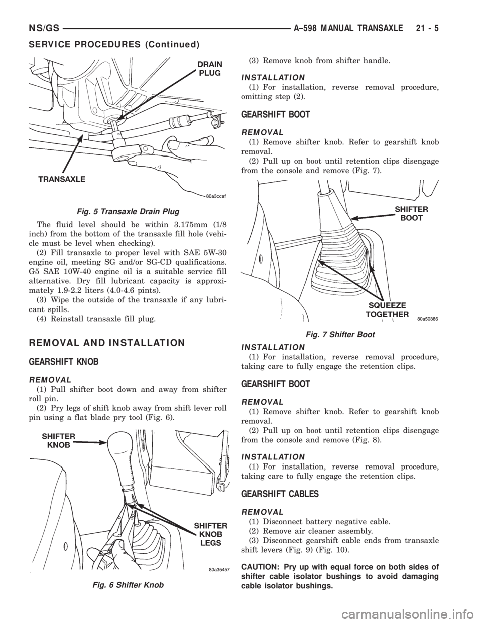
The fluid level should be within 3.175mm (1/8
inch) from the bottom of the transaxle fill hole (vehi-
cle must be level when checking).
(2) Fill transaxle to proper level with SAE 5W-30
engine oil, meeting SG and/or SG-CD qualifications.
G5 SAE 10W-40 engine oil is a suitable service fill
alternative. Dry fill lubricant capacity is approxi-
mately 1.9-2.2 liters (4.0-4.6 pints).
(3) Wipe the outside of the transaxle if any lubri-
cant spills.
(4) Reinstall transaxle fill plug.
REMOVAL AND INSTALLATION
GEARSHIFT KNOB
REMOVAL
(1) Pull shifter boot down and away from shifter
roll pin.
(2) Pry legs of shift knob away from shift lever roll
pin using a flat blade pry tool (Fig. 6).(3) Remove knob from shifter handle.
INSTALLATION
(1) For installation, reverse removal procedure,
omitting step (2).
GEARSHIFT BOOT
REMOVAL
(1) Remove shifter knob. Refer to gearshift knob
removal.
(2) Pull up on boot until retention clips disengage
from the console and remove (Fig. 7).
INSTALLATION
(1) For installation, reverse removal procedure,
taking care to fully engage the retention clips.
GEARSHIFT BOOT
REMOVAL
(1) Remove shifter knob. Refer to gearshift knob
removal.
(2) Pull up on boot until retention clips disengage
from the console and remove (Fig. 8).
INSTALLATION
(1) For installation, reverse removal procedure,
taking care to fully engage the retention clips.
GEARSHIFT CABLES
REMOVAL
(1) Disconnect battery negative cable.
(2) Remove air cleaner assembly.
(3) Disconnect gearshift cable ends from transaxle
shift levers (Fig. 9) (Fig. 10).
CAUTION: Pry up with equal force on both sides of
shifter cable isolator bushings to avoid damaging
cable isolator bushings.
Fig. 5 Transaxle Drain Plug
Fig. 6 Shifter Knob
Fig. 7 Shifter Boot
NS/GSA±598 MANUAL TRANSAXLE 21 - 5
SERVICE PROCEDURES (Continued)
Page 1662 of 1938
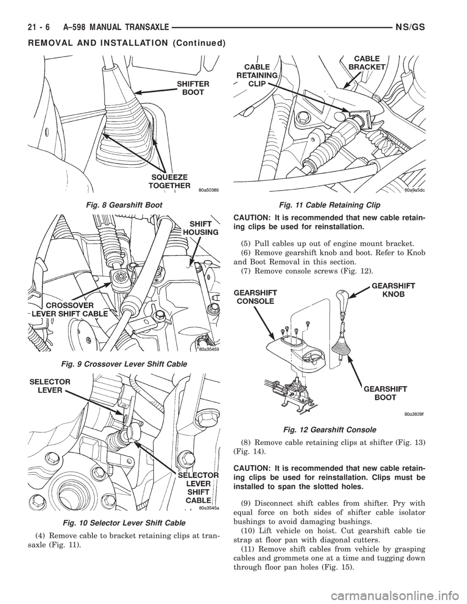
(4) Remove cable to bracket retaining clips at tran-
saxle (Fig. 11).CAUTION: It is recommended that new cable retain-
ing clips be used for reinstallation.
(5) Pull cables up out of engine mount bracket.
(6) Remove gearshift knob and boot. Refer to Knob
and Boot Removal in this section.
(7) Remove console screws (Fig. 12).
(8) Remove cable retaining clips at shifter (Fig. 13)
(Fig. 14).
CAUTION: It is recommended that new cable retain-
ing clips be used for reinstallation. Clips must be
installed to span the slotted holes.
(9) Disconnect shift cables from shifter. Pry with
equal force on both sides of shifter cable isolator
bushings to avoid damaging bushings.
(10) Lift vehicle on hoist. Cut gearshift cable tie
strap at floor pan with diagonal cutters.
(11) Remove shift cables from vehicle by grasping
cables and grommets one at a time and tugging down
through floor pan holes (Fig. 15).
Fig. 8 Gearshift Boot
Fig. 9 Crossover Lever Shift Cable
Fig. 10 Selector Lever Shift Cable
Fig. 11 Cable Retaining Clip
Fig. 12 Gearshift Console
21 - 6 A±598 MANUAL TRANSAXLENS/GS
REMOVAL AND INSTALLATION (Continued)
Page 1663 of 1938
INSTALLATION
(1) To install, reverse removal procedure. After
cables have been replaced, cable adjustment should
be checked. Refer to cable adjustment procedure in
this section.
NOTE: High temperature tie straps must be used
when replacing cable(s). Locate the new tie strap at
the white band on the crossover cable and cinch
cables tightly together.
CAUTION: Only the crossover cable is adjustable.
The selector cable does not have any adjustment
capabilities.
GEARSHIFT CABLESÐRHD VEHICLES
REMOVAL
(1) Disconnect battery negative cable.
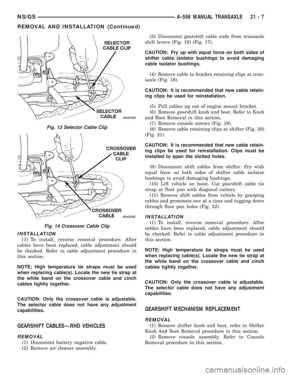
(2) Remove air cleaner assembly.(3) Disconnect gearshift cable ends from transaxle
shift levers (Fig. 16) (Fig. 17).
CAUTION: Pry up with equal force on both sides of
shifter cable isolator bushings to avoid damaging
cable isolator bushings.
(4) Remove cable to bracket retaining clips at tran-
saxle (Fig. 18).
CAUTION: It is recommended that new cable retain-
ing clips be used for reinstallation.
(5) Pull cables up out of engine mount bracket.
(6) Remove gearshift knob and boot. Refer to Knob
and Boot Removal in this section.
(7) Remove console screws (Fig. 19).
(8) Remove cable retaining clips at shifter (Fig. 20)
(Fig. 21).
CAUTION: It is recommended that new cable retain-
ing clips be used for reinstallation. Clips must be
installed to span the slotted holes.
(9) Disconnect shift cables from shifter. Pry with
equal force on both sides of shifter cable isolator
bushings to avoid damaging bushings.
(10) Lift vehicle on hoist. Cut gearshift cable tie
strap at floor pan with diagonal cutters.
(11) Remove shift cables from vehicle by grasping
cables and grommets one at a time and tugging down
through floor pan holes (Fig. 22).
INSTALLATION
(1) To install, reverse removal procedure. After
cables have been replaced, cable adjustment should
be checked. Refer to cable adjustment procedure in
this section.
NOTE: High temperature tie straps must be used
when replacing cable(s). Locate the new tie strap at
the white band on the crossover cable and cinch
cables tightly together.
CAUTION: Only the crossover cable is adjustable.
The selector cable does not have any adjustment
capabilities.
GEARSHIFT MECHANISM REPLACEMENT
REMOVAL
(1) Remove shifter knob and boot. refer to Shifter
Knob And Boot Removal procedure in this section.
(2) Remove console assembly. Refer to Console
Removal procedure in this section.
Fig. 13 Selector Cable Clip
Fig. 14 Crossover Cable Clip
NS/GSA±598 MANUAL TRANSAXLE 21 - 7
REMOVAL AND INSTALLATION (Continued)
Page 1668 of 1938
DIFFERENTIAL BEARING RETAINER AXLE
SEAL
REMOVAL
(1) Remove axle shaft. Refer to Group 2, Suspen-
sion and Driveshafts for service procedures.
(2) Insert a flat±blade pry tool into the axle seal
bore.
(3) Using the pry tool, carefully pop out the seal
taking care not to nick the seal bore.
INSTALLATION
(1) Clean axle shaft seal bore of any excess seal-
ant.
(2) Align axle shaft seal with axle shaft seal bore.
(3) Position axle seal at extension housing.
(4) Using Tool L-4520 and Tool C-4171, tap seal
into position.
SHIFT SHAFT SEALS
It isnotnecessary to remove the shift shaft cover
from the transaxle to service the shift shaft seals.
REMOVAL
(1) Remove the shift lever from the seal that is to
be serviced. Refer to shift lever removal for service
procedure.
(2) Using a pick tool, pry up on the shift shaft seal
and remove seal from bore.
INSTALLATION
(1) Position new shift shaft seal in bore.
(2) Install shift shaft seal into bore using an
appropriate size deep±well socket.
TRANSAXLE
The following items can be serviced without remov-
ing the transaxle from the vehicle:
²Gearshift housing
²5th speed synchronizer
²5th speed gear
²Roller detents and springs
²Speedometer pinion
²Vehicle speed sensor
²Bearing retainer plate.
²All external covers
²Shift shaft seals
²Axle shaft seals
To service any other component of the A-598 tran-
saxle you must remove it from the vehicle.
REMOVAL
(1) Disconnect battery negative cable.
(2) Remove air intake hose. Disconnect air mass
meter connector.
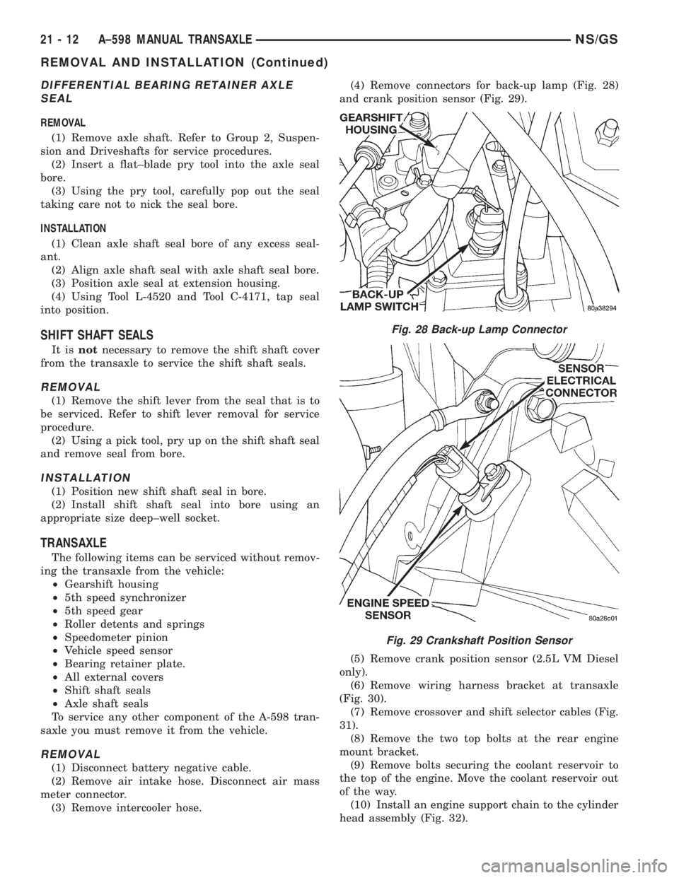
(3) Remove intercooler hose.(4) Remove connectors for back-up lamp (Fig. 28)
and crank position sensor (Fig. 29).
(5) Remove crank position sensor (2.5L VM Diesel
only).
(6) Remove wiring harness bracket at transaxle
(Fig. 30).
(7) Remove crossover and shift selector cables (Fig.
31).
(8) Remove the two top bolts at the rear engine
mount bracket.
(9) Remove bolts securing the coolant reservoir to
the top of the engine. Move the coolant reservoir out
of the way.
(10) Install an engine support chain to the cylinder
head assembly (Fig. 32).
Fig. 28 Back-up Lamp Connector
Fig. 29 Crankshaft Position Sensor
21 - 12 A±598 MANUAL TRANSAXLENS/GS
REMOVAL AND INSTALLATION (Continued)