Page 1669 of 1938
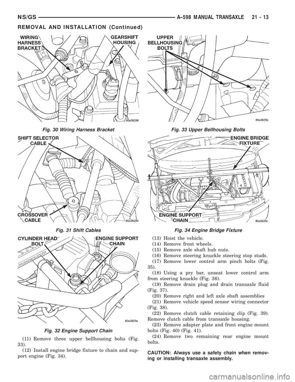
(11) Remove three upper bellhousing bolts (Fig.
33).
(12) Install engine bridge fixture to chain and sup-
port engine (Fig. 34).(13) Hoist the vehicle.
(14) Remove front wheels.
(15) Remove axle shaft hub nuts.
(16) Remove steering knuckle steering stop studs.
(17) Remove lower control arm pinch bolts (Fig.
35).
(18) Using a pry bar, unseat lower control arm
from steering knuckle (Fig. 36).
(19) Remove drain plug and drain transaxle fluid
(Fig. 37).
(20) Remove right and left axle shaft assemblies
(21) Remove vehicle speed sensor wiring connector
(Fig. 38).
(22) Remove clutch cable retaining clip (Fig. 39).
Remove clutch cable from transaxle housing.
(23) Remove adapter plate and front engine mount
bolts (Fig. 40) (Fig. 41).
(24) Remove two remaining rear engine mount
bolts.
CAUTION: Always use a safety chain when remov-
ing or installing transaxle assembly.
Fig. 30 Wiring Harness Bracket
Fig. 31 Shift Cables
Fig. 32 Engine Support Chain
Fig. 33 Upper Bellhousing Bolts
Fig. 34 Engine Bridge Fixture
NS/GSA±598 MANUAL TRANSAXLE 21 - 13
REMOVAL AND INSTALLATION (Continued)
Page 1671 of 1938
(4) Check the transaxle for leaks and recheck the
level of the transaxle lubricant.
INPUT SHAFT FRONT BEARING RETAINER
REMOVAL
(1) Remove the transaxle assembly from the vehi-
cle. For removal procedure, refer to Transaxle,
Removal and Installation.
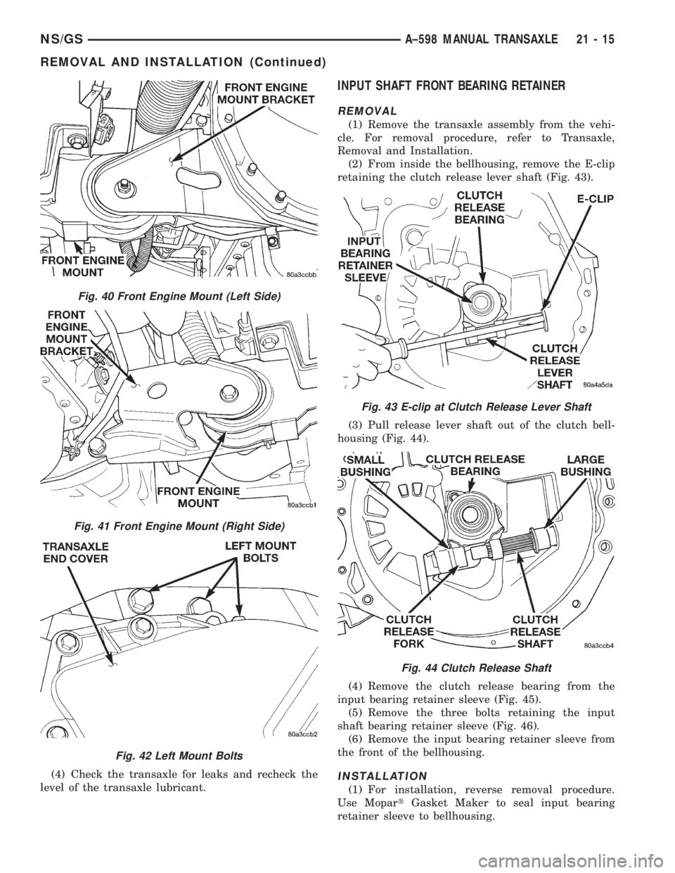
(2) From inside the bellhousing, remove the E-clip
retaining the clutch release lever shaft (Fig. 43).
(3) Pull release lever shaft out of the clutch bell-
housing (Fig. 44).
(4) Remove the clutch release bearing from the
input bearing retainer sleeve (Fig. 45).
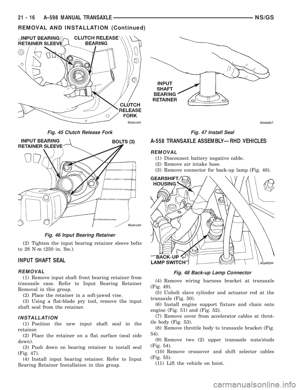
(5) Remove the three bolts retaining the input
shaft bearing retainer sleeve (Fig. 46).
(6) Remove the input bearing retainer sleeve from
the front of the bellhousing.
INSTALLATION
(1) For installation, reverse removal procedure.
Use MopartGasket Maker to seal input bearing
retainer sleeve to bellhousing.
Fig. 40 Front Engine Mount (Left Side)
Fig. 41 Front Engine Mount (Right Side)
Fig. 42 Left Mount Bolts
Fig. 43 E-clip at Clutch Release Lever Shaft
Fig. 44 Clutch Release Shaft
NS/GSA±598 MANUAL TRANSAXLE 21 - 15
REMOVAL AND INSTALLATION (Continued)
Page 1672 of 1938
(2) Tighten the input bearing retainer sleeve bolts
to 28 N´m (250 in. lbs.).
INPUT SHAFT SEAL
REMOVAL
(1) Remove input shaft front bearing retainer from
transaxle case. Refer to Input Bearing Retainer
Removal in this group.
(2) Place the retainer in a soft-jawed vise.
(3) Using a flat-blade pry tool, remove the input
shaft seal from the retainer.
INSTALLATION
(1) Position the new input shaft seal in the
retainer.
(2) Place the retainer on a flat surface (seal side
down).
(3) Push down on bearing retainer to install seal
(Fig. 47).
(4) Install input bearing retainer. Refer to Input
Bearing Retainer Installation in this group.
A-558 TRANSAXLE ASSEMBLYÐRHD VEHICLES
REMOVAL
(1) Disconnect battery negative cable.
(2) Remove air intake hose.
(3) Remove connector for back-up lamp (Fig. 48).
(4) Remove wiring harness bracket at transaxle
(Fig. 49).
(5) Unbolt slave cylinder and actuator rod at the
transaxle (Fig. 50).
(6) Install engine support fixture and chain onto
engine (Fig. 51) and (Fig. 52).
(7) Remove cover from accelerator cables at throt-
tle body (Fig. 53).
(8) Remove throttle body to transaxle bracket (Fig.
54).
(9) Remove two (2) upper transaxle nuts/studs
(Fig. 54).
(10) Remove crossover and shift selector cables
(Fig. 55).
(11) Lift the vehicle on hoist.
Fig. 45 Clutch Release Fork
Fig. 46 Input Bearing Retainer
Fig. 47 Install Seal
Fig. 48 Back-up Lamp Connector
21 - 16 A±598 MANUAL TRANSAXLENS/GS
REMOVAL AND INSTALLATION (Continued)
Page 1673 of 1938
Fig. 49 Wiring Harness Bracket
Fig. 50 Hydraulic Clutch Linkage
Fig. 51 Engine Bridge Fixture
NS/GSA±598 MANUAL TRANSAXLE 21 - 17
REMOVAL AND INSTALLATION (Continued)
Page 1674 of 1938
(12) Remove the front wheels.(13) Remove the two (2) axle shaft hub nuts.
(14) Remove three upper bellhousing bolts.
(15) Remove steering stop studs at steering knuck-
les.
(16) Remove lower control arm pinch bolts (Fig.
56).
(17) Using a pry bar, unseat lower control arm
from steering knuckle (Fig. 57).
(18) Remove drain plug and drain transaxle fluid
(Fig. 58).
(19) Remove right and left axle shaft assemblies
(20) Remove vehicle speed sensor wiring connector
(Fig. 59).
(21) Remove structural brace from engine and
transaxle.
Fig. 52 Engine Support Chain Ð Typical
Fig. 53 Throttle Control Shield
Fig. 54 Throttle Control Support Bracket
Fig. 55 Shift Cables
Fig. 56 Lower Control Arm Pinch Bolt
21 - 18 A±598 MANUAL TRANSAXLENS/GS
REMOVAL AND INSTALLATION (Continued)
Page 1675 of 1938
(22) Remove lower starter bolt.
(23) Remove engine wiring harness clip.
CAUTION: Always use a safety chain when remov-
ing or installing transaxle assembly.
(24) Place a transmission jack under the transmis-
sion
(25) Remove the transaxle lower dust cover.
(26) Remove the access cover in right splash shield
to access torsional damper bolt.
(27) Remove drive plate to modular clutch bolts
while holding torsional damper bolt with socket and
ratchet. To avoid distortion of the drive plate, remove
the modular clutch bolts a few turns at a time. Use a
crisscross pattern until all bolts are loosened.
(28) Unbolt rear engine mount through bolt and
two (2) mount bolts.
(29) Remove the left front fender splash shield.
(30) Unbolt left engine mount through bolt and
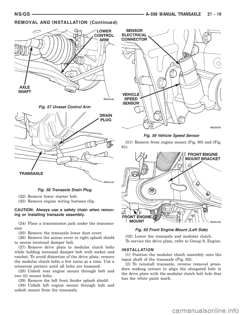
unbolt mount from the transaxle.(31) Remove front engine mount (Fig. 60) and (Fig.
61).
(32) Lower the transaxle and modular clutch.
To service the drive plate, refer to Group 9, Engine.
INSTALLATION
(1) Position the modular clutch assembly onto the
input shaft of the transaxle (Fig. 62).
(2) To reinstall transaxle, reverse removal proce-
dure making certain to align the elongated hole in
the drive plate with the modular clutch bolt hole that
has the white paint mark.
Fig. 57 Unseat Control Arm
Fig. 58 Transaxle Drain Plug
Fig. 59 Vehicle Speed Sensor
Fig. 60 Front Engine Mount (Left Side)
NS/GSA±598 MANUAL TRANSAXLE 21 - 19
REMOVAL AND INSTALLATION (Continued)
Page 1676 of 1938
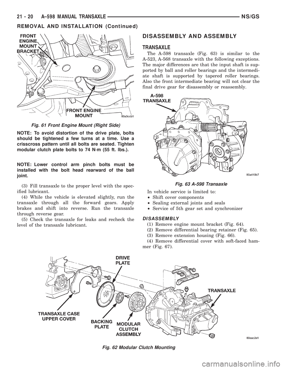
NOTE: To avoid distortion of the drive plate, bolts
should be tightened a few turns at a time. Use a
crisscross pattern until all bolts are seated. Tighten
modular clutch plate bolts to 74 N´m (55 ft. lbs.).
NOTE: Lower control arm pinch bolts must be
installed with the bolt head rearward of the ball
joint.
(3) Fill transaxle to the proper level with the spec-
ified lubricant.
(4) While the vehicle is elevated slightly, run the
transaxle through all the forward gears. Apply
brakes and shift into reverse. Run the transaxle
through reverse gear.
(5) Check the transaxle for leaks and recheck the
level of the transaxle lubricant.
DISASSEMBLY AND ASSEMBLY
TRANSAXLE
The A-598 transaxle (Fig. 63) is similar to the
A-523, A-568 transaxle with the following exceptions.
The major differences are that the input shaft is sup-
ported by ball and roller bearings and the intermedi-
ate shaft is supported by tapered roller bearings.
Also the front intermediate bearing will not clear the
final drive gear for disassembly or reassembly.
In vehicle service is limited to:
²Shift cover components
²Sealing external joints and seals
²Service of 5th gear set and synchronizer
DISASSEMBLY
(1) Remove engine mount bracket (Fig. 64).
(2) Remove differential bearing retainer (Fig. 65).
(3) Remove extension housing (Fig. 66).
(4) Remove differential cover with soft-faced ham-
mer (Fig. 67).
Fig. 62 Modular Clutch Mounting
Fig. 61 Front Engine Mount (Right Side)
Fig. 63 A-598 Transaxle
21 - 20 A±598 MANUAL TRANSAXLENS/GS
REMOVAL AND INSTALLATION (Continued)
Page 1677 of 1938
(5) Remove differential assembly (Fig. 68) (Fig.
69).CAUTION: Shift detent springs are located under-
neath shift cover. Remove shift cover carefully.
(6) Remove shift cover (Fig. 70) (Fig. 72).
Fig. 64 Engine Mount Bracket
Fig. 65 Differential Bearing Retainer
Fig. 66 Extension Housing
Fig. 67 Differential Cover
Fig. 68 Differential
Fig. 69 Differential Components
NS/GSA±598 MANUAL TRANSAXLE 21 - 21
DISASSEMBLY AND ASSEMBLY (Continued)