1996 CHRYSLER VOYAGER service indicator
[x] Cancel search: service indicatorPage 1146 of 1938
NOTE: Worn valve guides or cocked springs are
sometimes mistaken for noisy tappets. If such is
the case, noise may be dampened by applying side
thrust on the valve spring. If noise is not apprecia-
bly reduced, it can be assumed the noise is in the
tappet. Inspect the rocker arm push rod sockets
and push rod ends for wear.
Valve tappet noise ranges from light noise to a
heavy click. A light noise is usually caused by exces-
sive leak-down around the unit plunger which will
necessitate replacing the tappet, or by the plunger
partially sticking in the tappet body cylinder. A heavy
click is caused either by a tappet check valve not
seating, or by foreign particles becoming wedged
between the plunger and the tappet body causing the
plunger to stick in the down position. This heavy
click will be accompanied by excessive clearance
between the valve stem and rocker arm as valve
closes. In either case, tappet assembly should be
removed for inspection and cleaning.
CHECKING ENGINE OIL PRESSURE
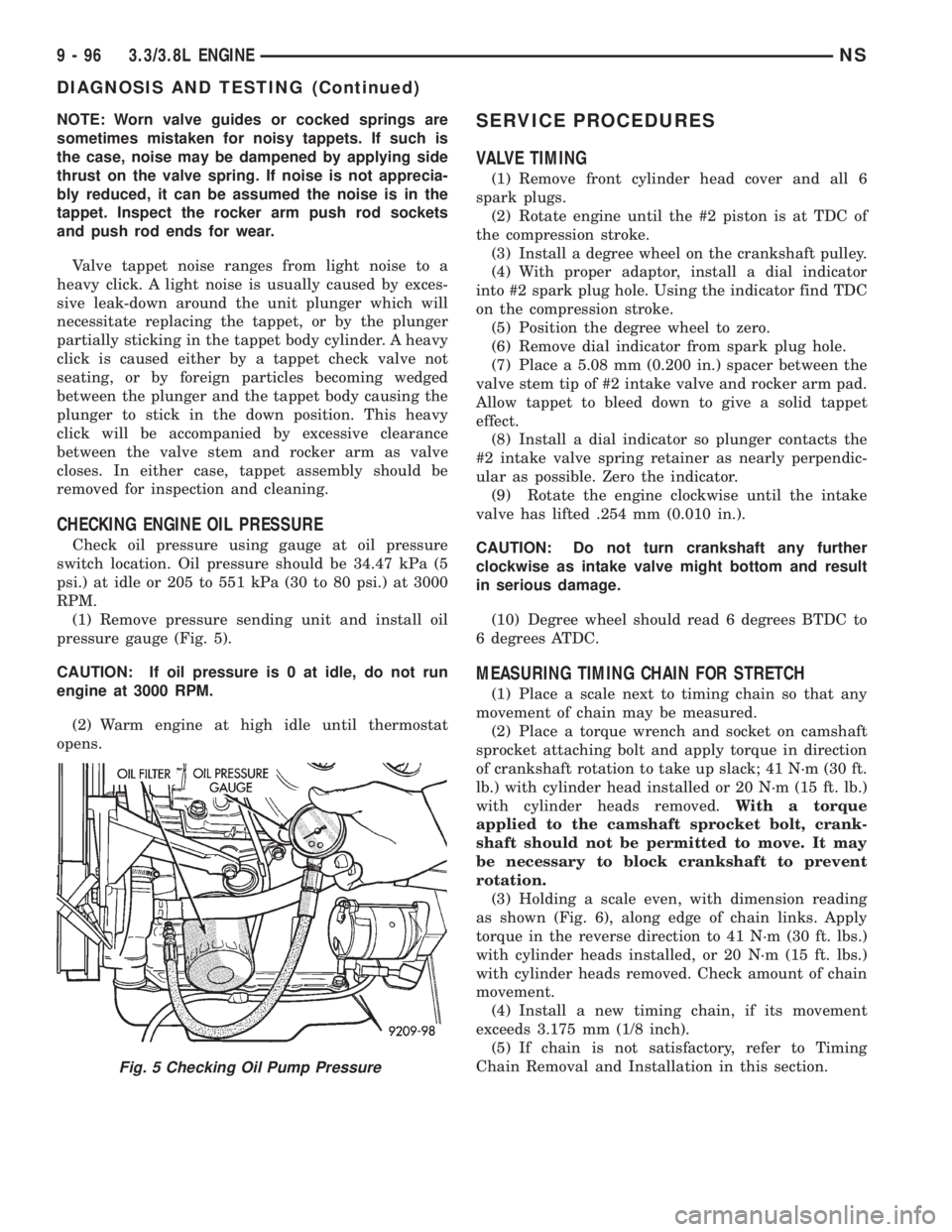
Check oil pressure using gauge at oil pressure
switch location. Oil pressure should be 34.47 kPa (5
psi.) at idle or 205 to 551 kPa (30 to 80 psi.) at 3000
RPM.
(1) Remove pressure sending unit and install oil
pressure gauge (Fig. 5).
CAUTION: If oil pressure is 0 at idle, do not run
engine at 3000 RPM.
(2) Warm engine at high idle until thermostat
opens.
SERVICE PROCEDURES
VALVE TIMING
(1) Remove front cylinder head cover and all 6
spark plugs.
(2) Rotate engine until the #2 piston is at TDC of
the compression stroke.
(3) Install a degree wheel on the crankshaft pulley.
(4) With proper adaptor, install a dial indicator
into #2 spark plug hole. Using the indicator find TDC
on the compression stroke.
(5) Position the degree wheel to zero.
(6) Remove dial indicator from spark plug hole.
(7) Place a 5.08 mm (0.200 in.) spacer between the
valve stem tip of #2 intake valve and rocker arm pad.
Allow tappet to bleed down to give a solid tappet
effect.
(8) Install a dial indicator so plunger contacts the
#2 intake valve spring retainer as nearly perpendic-
ular as possible. Zero the indicator.
(9) Rotate the engine clockwise until the intake
valve has lifted .254 mm (0.010 in.).
CAUTION: Do not turn crankshaft any further
clockwise as intake valve might bottom and result
in serious damage.
(10) Degree wheel should read 6 degrees BTDC to
6 degrees ATDC.
MEASURING TIMING CHAIN FOR STRETCH
(1) Place a scale next to timing chain so that any
movement of chain may be measured.
(2) Place a torque wrench and socket on camshaft
sprocket attaching bolt and apply torque in direction
of crankshaft rotation to take up slack; 41 N´m (30 ft.
lb.) with cylinder head installed or 20 N´m (15 ft. lb.)
with cylinder heads removed.With a torque
applied to the camshaft sprocket bolt, crank-
shaft should not be permitted to move. It may
be necessary to block crankshaft to prevent
rotation.
(3) Holding a scale even, with dimension reading
as shown (Fig. 6), along edge of chain links. Apply
torque in the reverse direction to 41 N´m (30 ft. lbs.)
with cylinder heads installed, or 20 N´m (15 ft. lbs.)
with cylinder heads removed. Check amount of chain
movement.
(4) Install a new timing chain, if its movement
exceeds 3.175 mm (1/8 inch).
(5) If chain is not satisfactory, refer to Timing
Chain Removal and Installation in this section.
Fig. 5 Checking Oil Pump Pressure
9 - 96 3.3/3.8L ENGINENS
DIAGNOSIS AND TESTING (Continued)
Page 1149 of 1938
PLASTIGAGE (OIL CLEARANCE)
MEASUREMENT
(1) Remove oil from journal and bearing shell.
(2) Install crankshaft.
(3) Cut plastigage to same length as width of the
bearing and place it in parallel with the journal axis
(Fig. 15).
(4) Install the main bearing cap carefully and
tighten the bolts to specified torque.
CAUTION: Do not rotate crankshaft or the plasti-
gage will be smeared.(5) Carefully remove the bearing cap and measure
the width of the plastigage at the widest part using
the scale on the plastigage package (Fig. 15). Refer to
Crankshaft Specification Chart for proper clearances.
If the clearance exceeds the specified limits, replace
the main bearing(s) and if necessary, have the crank-
shaft machined to next undersize.
CAUTION: Do not rotate crankshaft or the Plasti-
gage may be smeared.
CRANKSHAFT END PLAY
DIAL INDICATOR METHOD
(1) Mount a dial indicator to front of engine, locat-
ing probe on nose of crankshaft (Fig. 16).
Fig. 12 Checking Connecting Rod Side Clearance
CONNECTING ROD SPECIFICATION CHART
Connecting Rod Bearing Clearance
New Part: 0.019 - 0.073 mm
(0.0008 - 0.0029 in.)
Wear Limit: 0.074 mm
(0.003 in.)
Connecting Rod Side Clearance
New Part: 0.13 - 0.32 mm
(0.005 - 0.013 in.)
Wear Limit: 0.38 mm
(0.015 in.)
Fig. 13 Check for Stretched (Necked) Bolts
CRANKSHAFT SPECIFICATION CHART
Crankshaft End-Play
New Part: 0.09 - 0.24 mm
(0.0036 - 0.0095 in.)
Wear Limit: 0.38 mm
(0.015 in.)
Main Bearing Clearance
New Part: 0.011 - 0.059 mm
(0.0005 - 0.0024 in.)
Wear Limit: 0.076 mm
(0.003 in.)
Crankshaft Main Bearing Journal
Standard Size: 63.992 - 64.013 mm
(2.5194 - 2.5202 in.)
Crankshaft Connecting Rod Journal
Standard Size: 57.989 - 58.005 mm
(2.2831 - 2.2837 in.)
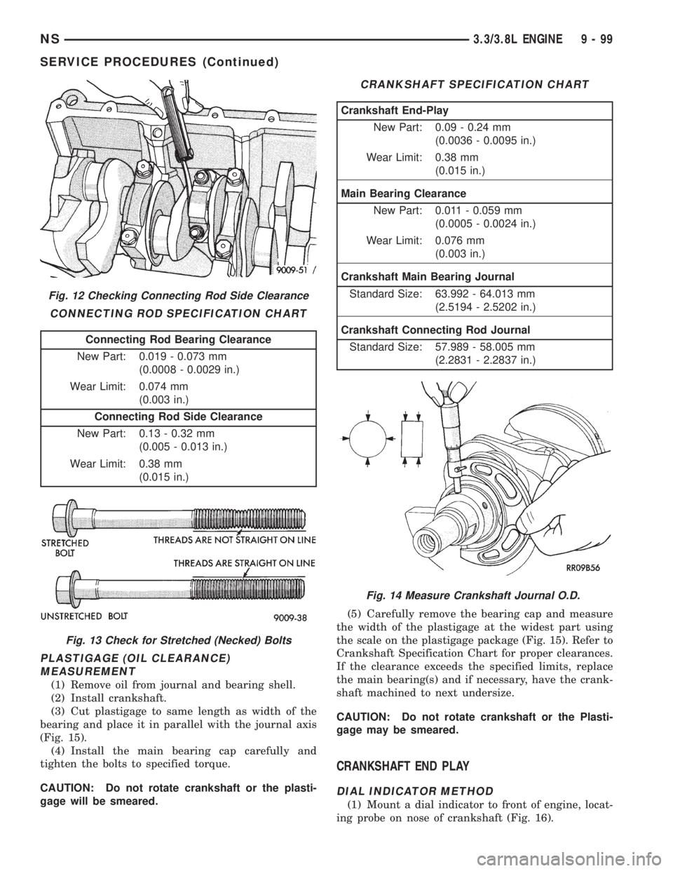
Fig. 14 Measure Crankshaft Journal O.D.
NS3.3/3.8L ENGINE 9 - 99
SERVICE PROCEDURES (Continued)
Page 1150 of 1938
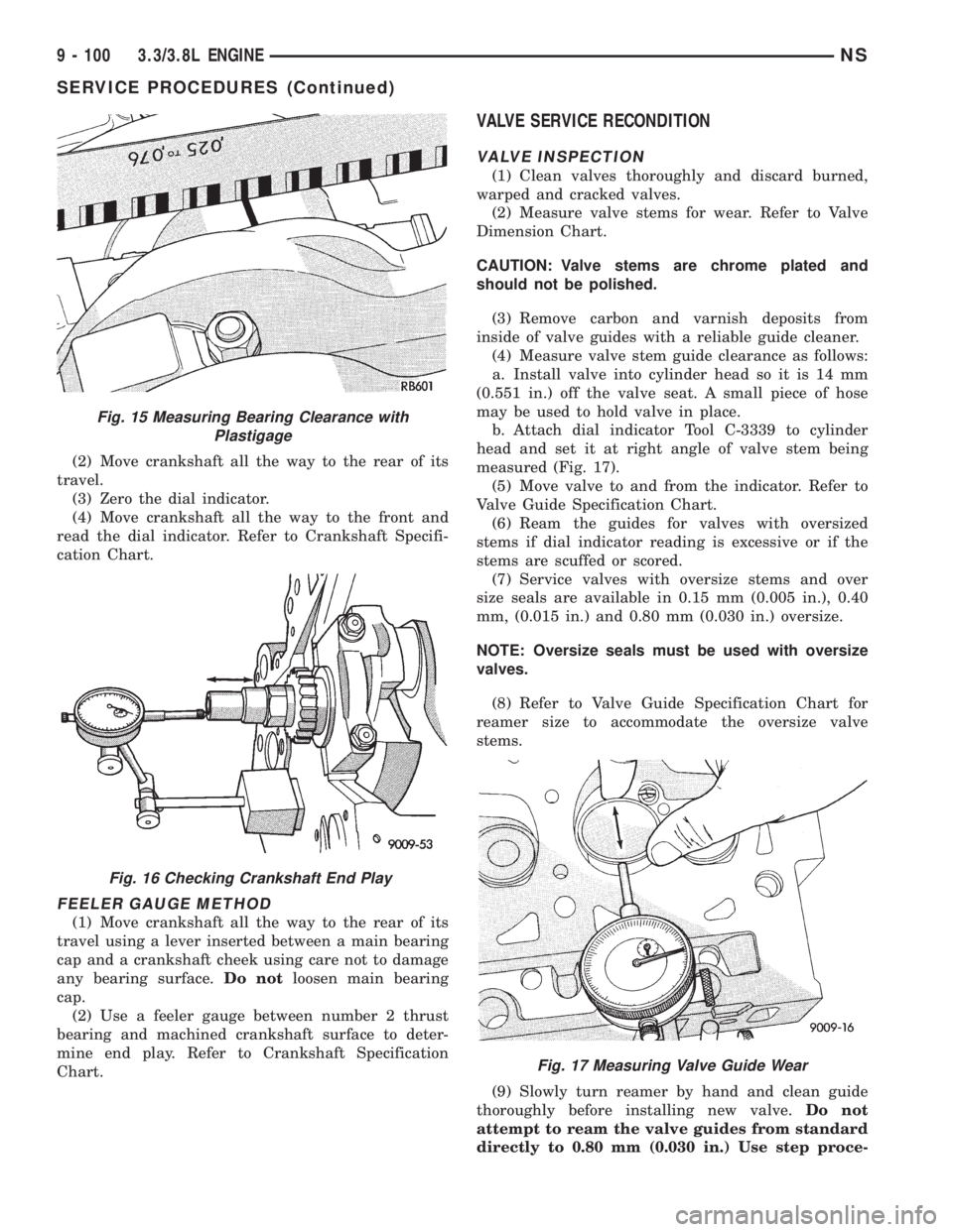
(2) Move crankshaft all the way to the rear of its
travel.
(3) Zero the dial indicator.
(4) Move crankshaft all the way to the front and
read the dial indicator. Refer to Crankshaft Specifi-
cation Chart.
FEELER GAUGE METHOD
(1) Move crankshaft all the way to the rear of its
travel using a lever inserted between a main bearing
cap and a crankshaft cheek using care not to damage
any bearing surface.Do notloosen main bearing
cap.
(2) Use a feeler gauge between number 2 thrust
bearing and machined crankshaft surface to deter-
mine end play. Refer to Crankshaft Specification
Chart.
VALVE SERVICE RECONDITION
VALVE INSPECTION
(1) Clean valves thoroughly and discard burned,
warped and cracked valves.
(2) Measure valve stems for wear. Refer to Valve
Dimension Chart.
CAUTION: Valve stems are chrome plated and
should not be polished.
(3) Remove carbon and varnish deposits from
inside of valve guides with a reliable guide cleaner.
(4) Measure valve stem guide clearance as follows:
a. Install valve into cylinder head so it is 14 mm
(0.551 in.) off the valve seat. A small piece of hose
may be used to hold valve in place.
b. Attach dial indicator Tool C-3339 to cylinder
head and set it at right angle of valve stem being
measured (Fig. 17).
(5) Move valve to and from the indicator. Refer to
Valve Guide Specification Chart.
(6) Ream the guides for valves with oversized
stems if dial indicator reading is excessive or if the
stems are scuffed or scored.
(7) Service valves with oversize stems and over
size seals are available in 0.15 mm (0.005 in.), 0.40
mm, (0.015 in.) and 0.80 mm (0.030 in.) oversize.
NOTE: Oversize seals must be used with oversize
valves.
(8) Refer to Valve Guide Specification Chart for
reamer size to accommodate the oversize valve
stems.
(9) Slowly turn reamer by hand and clean guide
thoroughly before installing new valve.Do not
attempt to ream the valve guides from standard
directly to 0.80 mm (0.030 in.) Use step proce-
Fig. 15 Measuring Bearing Clearance with
Plastigage
Fig. 16 Checking Crankshaft End Play
Fig. 17 Measuring Valve Guide Wear
9 - 100 3.3/3.8L ENGINENS
SERVICE PROCEDURES (Continued)
Page 1151 of 1938
dure of 0.15 mm (0.005 in.), 0.40 mm (0.015 in.)
and 0.80 mm (0.030 in.) so the valve guides may
be reamed true in relation to the valve seat.
After reaming guides, the seat runout should be
measured and resurfaced if necessary. See
Refacing Valves and Valve Seats.VALVE GUIDES
NOTE: Replace cylinder head if guide does not
clean up with 0.80 mm (0.030 in.) oversize reamer,
or if guide is loose in cylinder head.
REFACING VALVES AND VALVE SEATS
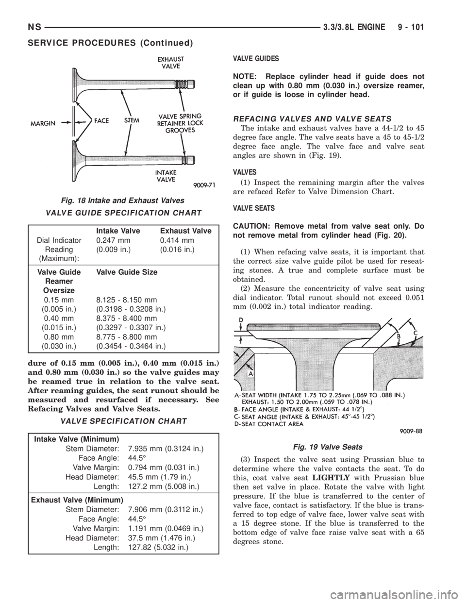
The intake and exhaust valves have a 44-1/2 to 45
degree face angle. The valve seats have a 45 to 45-1/2
degree face angle. The valve face and valve seat
angles are shown in (Fig. 19).
VALVES
(1) Inspect the remaining margin after the valves
are refaced Refer to Valve Dimension Chart.
VALVE SEATS
CAUTION: Remove metal from valve seat only. Do
not remove metal from cylinder head (Fig. 20).
(1) When refacing valve seats, it is important that
the correct size valve guide pilot be used for reseat-
ing stones. A true and complete surface must be
obtained.
(2) Measure the concentricity of valve seat using
dial indicator. Total runout should not exceed 0.051
mm (0.002 in.) total indicator reading.
(3) Inspect the valve seat using Prussian blue to
determine where the valve contacts the seat. To do
this, coat valve seatLIGHTLYwith Prussian blue
then set valve in place. Rotate the valve with light
pressure. If the blue is transferred to the center of
valve face, contact is satisfactory. If the blue is trans-
ferred to top edge of valve face, lower valve seat with
a 15 degree stone. If the blue is transferred to the
bottom edge of valve face raise valve seat with a 65
degrees stone.
Fig. 18 Intake and Exhaust Valves
VALVE GUIDE SPECIFICATION CHART
Intake Valve Exhaust Valve
Dial Indicator
Reading
(Maximum):0.247 mm
(0.009 in.)0.414 mm
(0.016 in.)
Valve Guide
Reamer
OversizeValve Guide Size
0.15 mm
(0.005 in.)8.125 - 8.150 mm
(0.3198 - 0.3208 in.)
0.40 mm
(0.015 in.)8.375 - 8.400 mm
(0.3297 - 0.3307 in.)
0.80 mm
(0.030 in.)8.775 - 8.800 mm
(0.3454 - 0.3464 in.)
VALVE SPECIFICATION CHART
Intake Valve (Minimum)
Stem Diameter: 7.935 mm (0.3124 in.)
Face Angle: 44.5É
Valve Margin: 0.794 mm (0.031 in.)
Head Diameter: 45.5 mm (1.79 in.)
Length: 127.2 mm (5.008 in.)
Exhaust Valve (Minimum)
Stem Diameter: 7.906 mm (0.3112 in.)
Face Angle: 44.5É
Valve Margin: 1.191 mm (0.0469 in.)
Head Diameter: 37.5 mm (1.476 in.)
Length: 127.82 (5.032 in.)
Fig. 19 Valve Seats
NS3.3/3.8L ENGINE 9 - 101
SERVICE PROCEDURES (Continued)
Page 1184 of 1938
FITTING CRANKSHAFT BEARINGS
Refer to Measuring Main Bearing Clearance in
Standard Service Procedures. Refer to Crankshaft
Specification Chart for specifications.
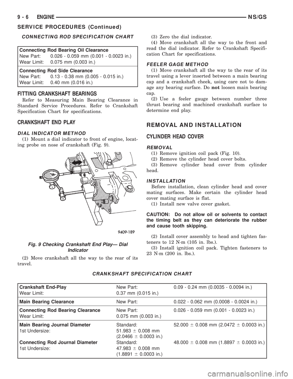
CRANKSHAFT END PLAY
DIAL INDICATOR METHOD
(1) Mount a dial indicator to front of engine, locat-
ing probe on nose of crankshaft (Fig. 9).
(2) Move crankshaft all the way to the rear of its
travel.(3) Zero the dial indicator.
(4) Move crankshaft all the way to the front and
read the dial indicator. Refer to Crankshaft Specifi-
cation Chart for specifications.
FEELER GAGE METHOD
(1) Move crankshaft all the way to the rear of its
travel using a lever inserted between a main bearing
cap and a crankshaft cheek, using care not to dam-
age any bearing surface. Donotloosen main bearing
cap.
(2) Use a feeler gauge between number three
thrust bearing and machined crankshaft surface to
determine end play.
REMOVAL AND INSTALLATION
CYLINDER HEAD COVER
REMOVAL
(1) Remove ignition coil pack (Fig. 10).
(2) Remove the cylinder head cover bolts.
(3) Remove cylinder head cover from cylinder
head.
INSTALLATION
Before installation, clean cylinder head and cover
mating surfaces. Make certain the cylinder head
cover mating surface is flat.
(1) Install new valve cover gasket.
CAUTION: Do not allow oil or solvents to contact
the timing belt as they can deteriorate the rubber
and cause tooth skipping.
(2) Install cover assembly to head and tighten fas-
teners to 12 N´m (105 in. lbs.).
(3) Install ignition coil pack. Tighten fasteners to
23 N´m (200 in. lbs.).
CONNECTING ROD SPECIFICATION CHART
Connecting Rod Bearing Oil Clearance
New Part: 0.026 - 0.059 mm (0.001 - 0.0023 in.)
Wear Limit: 0.075 mm (0.003 in.)
Connecting Rod Side Clearance
New Part: 0.13 - 0.38 mm (0.005 - 0.015 in.)
Wear Limit: 0.40 mm (0.016 in.)
CRANKSHAFT SPECIFICATION CHART
Crankshaft End-PlayNew Part: 0.09 - 0.24 mm (0.0035 - 0.0094 in.)
Wear Limit: 0.37 mm (0.015 in.)
Main Bearing ClearanceNew Part: 0.022 - 0.062 mm (0.0008 - 0.0024 in.)
Connecting Rod Bearing ClearanceNew Part: 0.026 - 0.059 mm (0.001 - 0.0023 in.)
Wear Limit: 0.075 mm (0.003 in.)
Main Bearing Journal DiameterStandard: 52.00060.008 mm (2.047260.0003 in.)
1st Undersize: 51.98360.008 mm
(2.046660.0003 in.)
Connecting Rod Journal DiameterStandard: 48.00060.008 mm (1.889760.0003 in.)
1st Undersize: 47.98360.008 mm
(1.889160.0003 in.)
Fig. 9 Checking Crankshaft End PlayÐ Dial
Indicator
9 - 6 ENGINENS/GS
SERVICE PROCEDURES (Continued)
Page 1208 of 1938
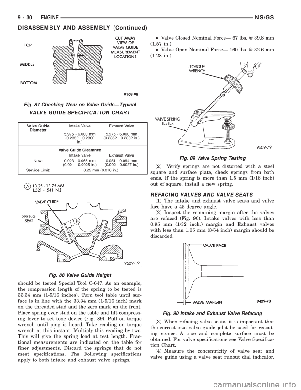
should be tested Special Tool C-647. As an example,
the compression length of the spring to be tested is
33.34 mm (1-5/16 inches). Turn tool table until sur-
face is in line with the 33.34 mm (1-5/16 inch) mark
on the threaded stud and the zero mark on the front.
Place spring over stud on the table and lift compress-
ing lever to set tone device (Fig. 89). Pull on torque
wrench until ping is heard. Take reading on torque
wrench at this instant. Multiply this reading by two.
This will give the spring load at test length. Frac-
tional measurements are indicated on the table for
finer adjustments. Discard the springs that do not
meet specifications. The Following specifications
apply to both intake and exhaust valve springs.²Valve Closed Nominal ForceÐ 67 lbs. @ 39.8 mm
(1.57 in.)
²Valve Open Nominal ForceÐ 160 lbs. @ 32.6 mm
(1.28 in.)
(2) Verify springs are not distorted with a steel
square and surface plate, check springs from both
ends. If the spring is more than 1.5 mm (1/16 inch)
out of square, install a new spring.
REFACING VALVES AND VALVE SEATS
(1) The intake and exhaust valve seats and valve
face have a 45 degree angle.
(2) Inspect the remaining margin after the valves
are refaced (Fig. 90). Intake valves with less than
0.95 mm (1/32 inch.) margin and Exhaust valves
with less than 1.05 mm (3/64 inch) margin should be
discarded.
(3) When refacing valve seats, it is important that
the correct size valve guide pilot be used for reseat-
ing stones. A true and complete surface must be
obtained. For valve specifications see Valve Specifica-
tion Chart.
(4) Measure the concentricity of valve seat and
valve guide using a valve seat runout dial indicator.
Fig. 87 Checking Wear on Valve GuideÐTypical
VALVE GUIDE SPECIFICATION CHART
Valve Guide
DiameterIntake Valve Exhaust Valve
5.975 - 6.000 mm
(0.2352 - 0.2362
in.)5.975 - 6.000 mm
(0.2352 - 0.2362 in.)
Valve Guide Clearance
Intake Valve Exhaust Valve
New: 0.023 - 0.066 mm
(0.001 - 0.0025 in.)0.051 - 0.094 mm
(0.002 - 0.0037 in.)
Service Limit: 0.25 mm (0.010 in.)
Fig. 88 Valve Guide Height
Fig. 89 Valve Spring Testing
Fig. 90 Intake and Exhaust Valve Refacing
9 - 30 ENGINENS/GS
DISASSEMBLY AND ASSEMBLY (Continued)
Page 1209 of 1938
Total runout should not exceed. 0.051 mm (0.002
inch.) (total indicator reading).
(5) Inspect the valve seat with Prussian blue to
determine where the valve contacts the seat. To do
this, coat valve seatLIGHTLYwith Prussian blue
then set valve in place. Rotate the valve with light
pressure. If the blue is transferred to the center of
valve face, contact is satisfactory. If the blue is trans-
ferred to top edge of the valve face, lower valve seat
with a 15 degrees stone. If the blue is transferred to
the bottom edge of valve face raise valve seat with a
65 degrees stone.
²Intake valve seat diameter is 33 mm (1.299 in.)
²Exhaust valve seat diameter is 28 mm (1.102
in.)
(6) Valve seats which are worn or burned can be
reworked, provided that correct angle and seat width
are maintained. The intake valve seat must be ser-
viced when the valve seat width is 2.0 mm (0.079 in.)
or greater. The exhaust valve seat must be serviced
when the valve seat width is 2.5 mm (0.098 in.) or
greater. Otherwise the cylinder head must be
replaced.
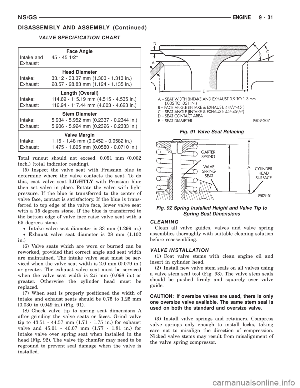
(7) When seat is properly positioned the width of
intake and exhaust seats should be 0.75 to 1.25 mm
(0.030 to 0.049 in.) (Fig. 91).
(8) Check valve tip to spring seat dimensions A
after grinding the valve seats or faces. Grind valve
tip to 43.51 - 44.57 mm (1.71 - 1.75 in.) for exhaust
valve and 45.01 - 46.07 mm (1.77 - 1.81 in.) for
intake valve over spring seat when installed in the
head (Fig. 92). The valve tip chamfer may need to be
reground to prevent seal damage when the valve is
installed.
CLEANING
Clean all valve guides, valves and valve spring
assemblies thoroughly with suitable cleaning solution
before reassembling.
VALVE INSTALLATION
(1) Coat valve stems with clean engine oil and
insert in cylinder head.
(2) Install new valve stem seals on all valves using
a valve stem seal tool (Fig. 93). The valve stem seals
should be pushed firmly and squarely over valve
guide.
CAUTION: If oversize valves are used, there is only
one oversize valve available. The same stem seal is
used on both the standard and oversize valve.
(3) Install valve springs and retainers. Compress
valve springs only enough to install locks, taking
care not to misalign the direction of compression.
Nicked valve stems may result from misalignment of
the valve spring compressor.
VALVE SPECIFICATION CHART
Face Angle
Intake and
Exhaust:45 - 45 1/2É
Head Diameter
Intake: 33.12 - 33.37 mm (1.303 - 1.313 in.)
Exhaust: 28.57 - 28.83 mm (1.124 - 1.135 in.)
Length (Overall)
Intake: 114.69 - 115.19 mm (4.515 - 4.535 in.)
Exhaust: 116.94 - 117.44 mm (4.603 - 4.623 in.)
Stem Diameter
Intake: 5.934 - 5.952 mm (0.2337 - 0.2344 in.)
Exhaust: 5.906 - 5.924 mm (0.2326 - 0.2333 in.)
Valve Margin
Intake: 1.15 - 1.48 mm (0.0452 - 0.0582 in.)
Exhaust: 1.475 - 1.805 mm (0.0580 - 0.0710 in.)
Fig. 91 Valve Seat Refacing
Fig. 92 Spring Installed Height and Valve Tip to
Spring Seat Dimensions
NS/GSENGINE 9 - 31
DISASSEMBLY AND ASSEMBLY (Continued)
Page 1228 of 1938
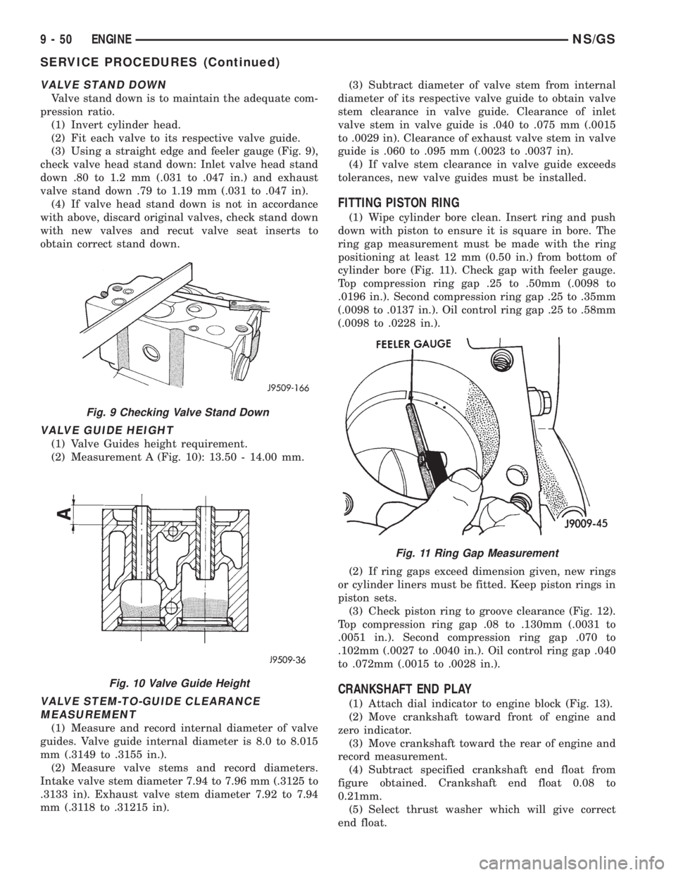
VALVE STAND DOWN
Valve stand down is to maintain the adequate com-
pression ratio.
(1) Invert cylinder head.
(2) Fit each valve to its respective valve guide.
(3) Using a straight edge and feeler gauge (Fig. 9),
check valve head stand down: Inlet valve head stand
down .80 to 1.2 mm (.031 to .047 in.) and exhaust
valve stand down .79 to 1.19 mm (.031 to .047 in).
(4) If valve head stand down is not in accordance
with above, discard original valves, check stand down
with new valves and recut valve seat inserts to
obtain correct stand down.
VALVE GUIDE HEIGHT
(1) Valve Guides height requirement.
(2) Measurement A (Fig. 10): 13.50 - 14.00 mm.
VALVE STEM-TO-GUIDE CLEARANCE
MEASUREMENT
(1) Measure and record internal diameter of valve
guides. Valve guide internal diameter is 8.0 to 8.015
mm (.3149 to .3155 in.).
(2) Measure valve stems and record diameters.
Intake valve stem diameter 7.94 to 7.96 mm (.3125 to
.3133 in). Exhaust valve stem diameter 7.92 to 7.94
mm (.3118 to .31215 in).(3) Subtract diameter of valve stem from internal
diameter of its respective valve guide to obtain valve
stem clearance in valve guide. Clearance of inlet
valve stem in valve guide is .040 to .075 mm (.0015
to .0029 in). Clearance of exhaust valve stem in valve
guide is .060 to .095 mm (.0023 to .0037 in).
(4) If valve stem clearance in valve guide exceeds
tolerances, new valve guides must be installed.
FITTING PISTON RING
(1) Wipe cylinder bore clean. Insert ring and push
down with piston to ensure it is square in bore. The
ring gap measurement must be made with the ring
positioning at least 12 mm (0.50 in.) from bottom of
cylinder bore (Fig. 11). Check gap with feeler gauge.
Top compression ring gap .25 to .50mm (.0098 to
.0196 in.). Second compression ring gap .25 to .35mm
(.0098 to .0137 in.). Oil control ring gap .25 to .58mm
(.0098 to .0228 in.).
(2) If ring gaps exceed dimension given, new rings
or cylinder liners must be fitted. Keep piston rings in
piston sets.
(3) Check piston ring to groove clearance (Fig. 12).
Top compression ring gap .08 to .130mm (.0031 to
.0051 in.). Second compression ring gap .070 to
.102mm (.0027 to .0040 in.). Oil control ring gap .040
to .072mm (.0015 to .0028 in.).
CRANKSHAFT END PLAY
(1) Attach dial indicator to engine block (Fig. 13).
(2) Move crankshaft toward front of engine and
zero indicator.
(3) Move crankshaft toward the rear of engine and
record measurement.
(4) Subtract specified crankshaft end float from
figure obtained. Crankshaft end float 0.08 to
0.21mm.
(5) Select thrust washer which will give correct
end float.
Fig. 9 Checking Valve Stand Down
Fig. 10 Valve Guide Height
Fig. 11 Ring Gap Measurement
9 - 50 ENGINENS/GS
SERVICE PROCEDURES (Continued)