1996 CHRYSLER VOYAGER service indicator
[x] Cancel search: service indicatorPage 1719 of 1938

TIRES AND WHEELS
CONTENTS
page page
TIRES.................................. 1WHEELS................................ 9
TIRES
INDEX
page page
DESCRIPTION AND OPERATION
RADIAL-PLY TIRES....................... 2
REPLACEMENT TIRES.................... 3
SPARE TIRE (TEMPORARY)................ 2
TIRE INFLATION PRESSURES.............. 2
TIRE INFORMATION...................... 1
TIRE PRESSURE FOR HIGH-SPEED DRIVING . . 3
DIAGNOSIS AND TESTING
LEAD CORRECTION CHART................ 4
PRESSURE GAUGES..................... 3
TIRE NOISE OR VIBRATION................ 4TIRE WEAR PATTERNS.................... 4
TREAD WEAR INDICATORS................ 3
SERVICE PROCEDURES
REPAIRING TIRE LEAKS................... 6
TIRE AND WHEEL MATCH MOUNTING........ 6
TIRE AND WHEEL ROTATION (NON-
DIRECTIONAL THREAD PATTERN).......... 6
CLEANING AND INSPECTION
CLEANING TIRES........................ 7
SPECIFICATIONS
TIRE SPECIFICATIONS.................... 8
DESCRIPTION AND OPERATION
TIRE INFORMATION
Tires are designed and engineered for each specific
vehicle. They provide the best overall performance
for normal operation. The ride and handling charac-
teristics match the vehicle's requirements. With
proper care they will give excellent reliability, trac-
tion, skid resistance, and tread life.
Driving habits have more effect on tire life than
any other factor. Careful drivers will obtain, in most
cases, much greater mileage than severe use or care-
less drivers. A few of the driving habits which will
shorten the life of any tire are:
²Rapid acceleration
²Severe application of brakes
²High-speed driving
²Taking turns at excessive speeds
²Striking curbs and other obstacles
Radial ply tires are more prone to irregular tread
wear. It is important to follow the tire rotation inter-
val shown in the section on Tire Rotation. This will
help to achieve a greater tread-life potential.
TIRE IDENTIFICATION
Tire type, size, aspect ratio and speed rating are
encoded in the letters and numbers imprinted on the
side wall of the tire. Refer to the chart to decipher
the tire identification code (Fig. 1).
Performance tires will have a speed rating letter
after the aspect ratio number. The speed rating is not
always printed on the tire sidewall. The letterSindi-
cates that the tire is speed rated up to 112 mph.
²Qup to 100 mph
²Tup to 118 mph
²Uup to 124 mph
²Hup to 130 mph
²Vup to 149 mph
²Zmore than 149 mph (consult the tire manu-
facturer for the specific speed rating)
An All Season type tire will have eitherM+S,M
&SorM±S(indicating mud and snow traction)
imprinted on the side wall.
TIRE CHAINS
This vehicle was designed to allow the use of a
specified type of snow chain on the tires. Only com-
pact snow chains or other traction aidsmeeting SAE
type ªClass Sº specifications may be used.Any style
NSTIRES AND WHEELS 22 - 1
Page 1724 of 1938

SERVICE PROCEDURES
TIRE AND WHEEL ROTATION (NON-DIRECTIONAL
THREAD PATTERN)
Tires on the front and rear axles operate at differ-
ent loads and perform different functions. For these
reasons, they wear at unequal rates, and tend to
develop irregular wear patterns. These effects can be
reduced by timely rotation of tires. The benefits of
rotation are especially worthwhile. Rotation will
increase tread life, help to maintain mud, snow, and
wet traction levels, and contribute to a smooth, quiet
ride.
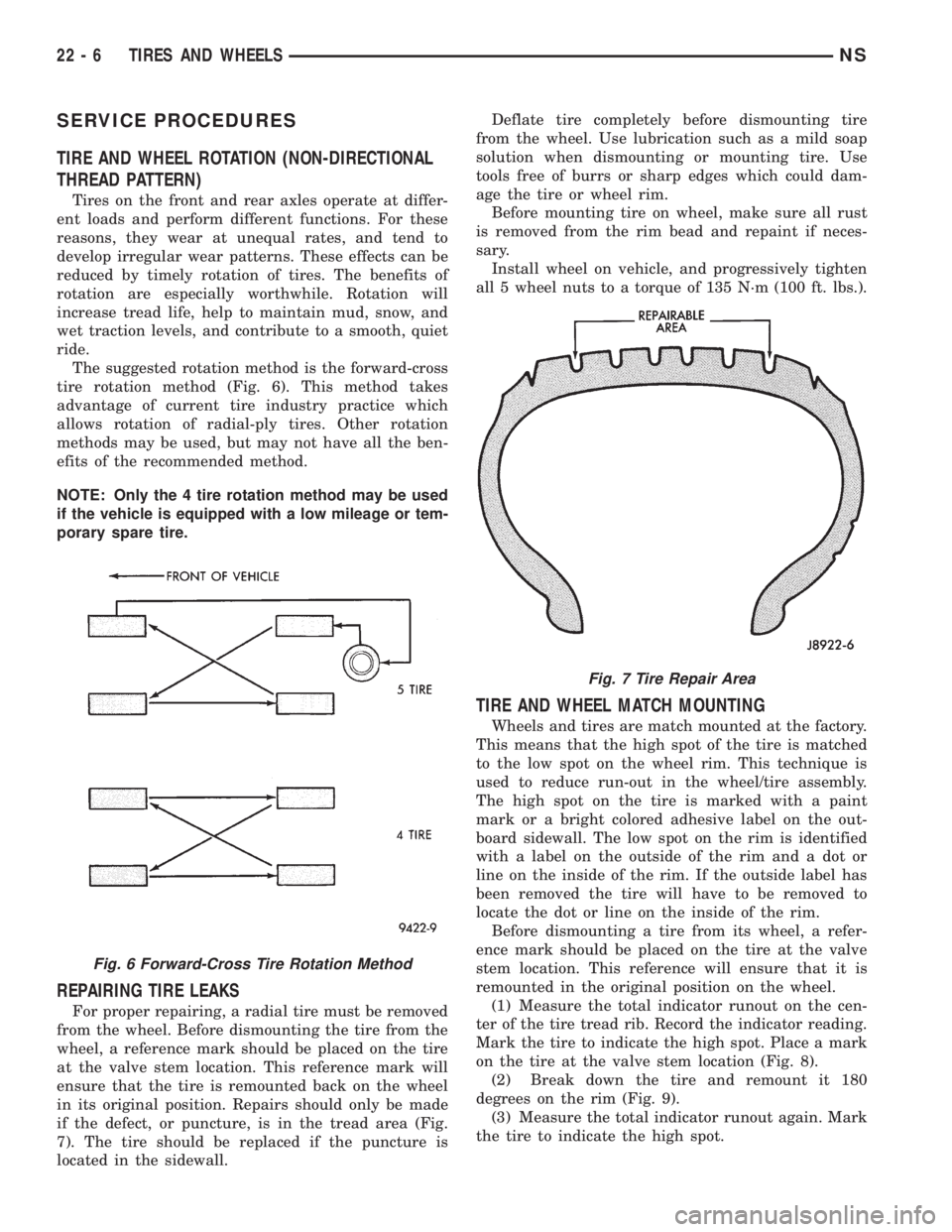
The suggested rotation method is the forward-cross
tire rotation method (Fig. 6). This method takes
advantage of current tire industry practice which
allows rotation of radial-ply tires. Other rotation
methods may be used, but may not have all the ben-
efits of the recommended method.
NOTE: Only the 4 tire rotation method may be used
if the vehicle is equipped with a low mileage or tem-
porary spare tire.
REPAIRING TIRE LEAKS
For proper repairing, a radial tire must be removed
from the wheel. Before dismounting the tire from the
wheel, a reference mark should be placed on the tire
at the valve stem location. This reference mark will
ensure that the tire is remounted back on the wheel
in its original position. Repairs should only be made
if the defect, or puncture, is in the tread area (Fig.
7). The tire should be replaced if the puncture is
located in the sidewall.Deflate tire completely before dismounting tire
from the wheel. Use lubrication such as a mild soap
solution when dismounting or mounting tire. Use
tools free of burrs or sharp edges which could dam-
age the tire or wheel rim.
Before mounting tire on wheel, make sure all rust
is removed from the rim bead and repaint if neces-
sary.
Install wheel on vehicle, and progressively tighten
all 5 wheel nuts to a torque of 135 N´m (100 ft. lbs.).
TIRE AND WHEEL MATCH MOUNTING
Wheels and tires are match mounted at the factory.
This means that the high spot of the tire is matched
to the low spot on the wheel rim. This technique is
used to reduce run-out in the wheel/tire assembly.
The high spot on the tire is marked with a paint
mark or a bright colored adhesive label on the out-
board sidewall. The low spot on the rim is identified
with a label on the outside of the rim and a dot or
line on the inside of the rim. If the outside label has
been removed the tire will have to be removed to
locate the dot or line on the inside of the rim.
Before dismounting a tire from its wheel, a refer-
ence mark should be placed on the tire at the valve
stem location. This reference will ensure that it is
remounted in the original position on the wheel.
(1) Measure the total indicator runout on the cen-
ter of the tire tread rib. Record the indicator reading.
Mark the tire to indicate the high spot. Place a mark
on the tire at the valve stem location (Fig. 8).
(2) Break down the tire and remount it 180
degrees on the rim (Fig. 9).
(3) Measure the total indicator runout again. Mark
the tire to indicate the high spot.
Fig. 6 Forward-Cross Tire Rotation Method
Fig. 7 Tire Repair Area
22 - 6 TIRES AND WHEELSNS
Page 1923 of 1938

the amount of EGR supplied to the engine. This pro-
vides the correct amount of exhaust gas recirculation
for different operating conditions.
This system does not allow EGR at idle. The EGR
systems can operate at all coolant temperatures
above 60ÉF as long as the battery ambient tempera-
ture is above 7ÉF.
DIAGNOSIS AND TESTING
EGR SYSTEM ON-BOARD DIAGNOSTICS
The PCM performs an on-board diagnostic check of
the EGR system. The diagnostic system uses the
electronic EGR transducer for the system tests.
The diagnostic check activates only during selected
engine/driving conditions. When the conditions are
met, the PCM energizes the transducer solenoid to
disable the EGR. The PCM checks for a change in
the heated oxygen sensor signal. If the air-fuel mix-
ture goes lean, the PCM will attempt to enrichen the
mixture. The PCM registers a Diagnostic Trouble
Code (DTC) if the EGR system is not operating cor-
rectly. After registering a DTC, the PCM turns on the
malfunction indicator (Check Engine) lamp after 2
consecutive trips. There are 2 types of failures sensed
by the PCM. The first is a short or open in the elec-
trical solenoid circuit. The second is a mechanical
failure or loss of vacuum. The Malfunction Indicator
Lamp (MIL) indicates the need for service.
If a problem is indicated by the MIL and a DTC for
the EGR system is set, check for proper operation of
the EGR system. Use the System Test, EGR Gas
Flow Test. If the EGR system tests properly, check
the system using the DRB scan tool. Refer to
On-Board Diagnosis sections in this Group. Also,
refer to the DRB scan tool and the appropriate Pow-
ertrain Diagnostics Procedure manual.
EGR SYSTEM TEST
WARNING: APPLY PARKING BRAKE AND/OR
BLOCK WHEELS BEFORE TESTING THE EGR SYS-
TEM.
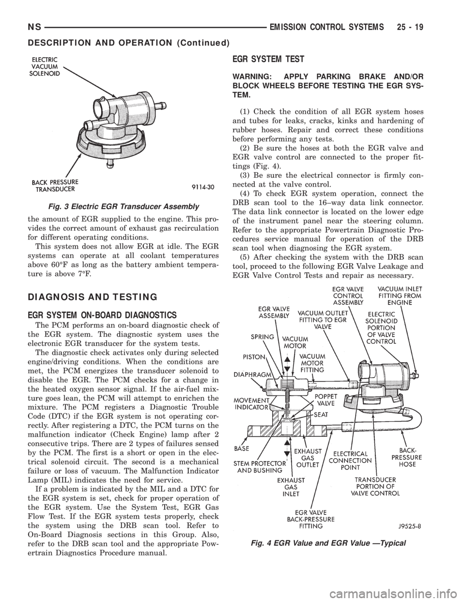
(1) Check the condition of all EGR system hoses
and tubes for leaks, cracks, kinks and hardening of
rubber hoses. Repair and correct these conditions
before performing any tests.
(2) Be sure the hoses at both the EGR valve and
EGR valve control are connected to the proper fit-
tings (Fig. 4).
(3) Be sure the electrical connector is firmly con-
nected at the valve control.
(4) To check EGR system operation, connect the
DRB scan tool to the 16±way data link connector.
The data link connector is located on the lower edge
of the instrument panel near the steering column.
Refer to the appropriate Powertrain Diagnostic Pro-
cedures service manual for operation of the DRB
scan tool when diagnosing the EGR system.
(5) After checking the system with the DRB scan
tool, proceed to the following EGR Valve Leakage and
EGR Valve Control Tests and repair as necessary.
Fig. 3 Electric EGR Transducer Assembly
Fig. 4 EGR Value and EGR Value ÐTypical
NSEMISSION CONTROL SYSTEMS 25 - 19
DESCRIPTION AND OPERATION (Continued)