1996 CHRYSLER VOYAGER service indicator
[x] Cancel search: service indicatorPage 1340 of 1938
Shutdown (ASD) RelayÐPCM Output in this section
for relay operation.
TORQUE CONVERTER CLUTCH SOLENOIDÐPCM
OUTPUT
Three-speed automatic transaxles use a torque con-
verter clutch solenoid. The PCM controls the engage-
ment of the torque converter clutch through the
solenoid. The torque converter clutch is engaged only
in direct drive mode. Refer to Group 21 for transaxle
information.
MALFUNCTION INDICATOR (CHECK ENGINE)
LAMPÐPCM OUTPUT
The PCM supplies the malfunction indicator (check
engine) lamp on/off signal to the instrument panel
through the CCD Bus. The CCD Bus is a communi-
cations port. Various modules use the CCD Bus to
exchange information.
The Check Engine lamp comes on each time the
ignition key is turned ON and stays on for 3 seconds
as a bulb test.
The Malfunction Indicator Lamp (MIL) stays on
continuously, when the PCM has entered a Limp-In
mode or identified a failed emission component. Dur-
ing Limp-in Mode, the PCM attempts to keep the
system operational. The MIL signals the need for
immediate service. In limp-in mode, the PCM com-
pensates for the failure of certain components that
send incorrect signals. The PCM substitutes for the
incorrect signals with inputs from other sensors.
If the PCM detects active engine misfire severe
enough to cause catalyst damage, it flashes the MIL.
At the same time the PCM also sets a Diagnostic
Trouble Code (DTC).
For signals that can trigger the MIL (Check
Engine Lamp) refer to Group 25, On-Board
Dianostics.
SOLID STATE FAN RELAYÐPCM OUTPUT
The radiator fan runs at a variable speed depend-
ing on coolant temperature and A/C system pressure.
The radiator fan circuit contains a Solid State Fan
Relay (SSFR). Refer to the Group 8W for a circuit
schematic.
A 5 volt signal is supplied to the SSFR. The PCM
provides a pulsed ground for the SSFR. Depending
upon the amount of pulse on time, the SSFR puts out
a proportional voltage to the fan motor at the lower
speed. For instance, if the on time is 30 percent, then
the voltage to the fan motor will be 3.6 volts.
When engine coolant reaches approximately 102ÉC
(215ÉF) the PCM grounds the SSFR relay. If engine
coolant reaches 207ÉC (225ÉF) the PCM grounds the
high speed ground relay and high speed fan relay. If
the fan operates at high speed, the PCM de-energizes
the high speed relay and high speed ground relay
when coolant temperature drops to approximately
101ÉC (214ÉF). When coolant temperature drops to
101ÉC (214ÉF) the fan operates at low speed. The
PCM de-energizes the low speed relay when coolant
temperature drops to approximately 93ÉC (199ÉF).
Also, when the air conditioning pressure switch
closes, the fan operates at high speed. The air condi-
tioning switch closes at 285 psi610 psi. When air
conditioning pressure drops approximately 40 psi, the
pressure switch opens and the fan operates at low
speed.
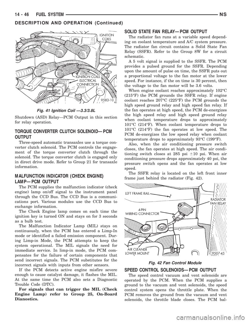
The SSFR relay is located on the left front inner
frame just behind the radiator (Fig. 42).
SPEED CONTROL SOLENOIDSÐPCM OUTPUT
The speed control vacuum and vent solenoids are
operated by the PCM. When the PCM supplies a
ground to the vacuum and vent solenoids, the speed
control system opens the throttle plate. When the
PCM removes the ground from the vacuum and vent
solenoids, the throttle blade closes. The PCM bal-
Fig. 41 Ignition Coil Ð3.3/3.8L
Fig. 42 Fan Control Module
14 - 46 FUEL SYSTEMNS
DESCRIPTION AND OPERATION (Continued)
Page 1379 of 1938
the intake manifold. Refer to Group 11, Exhaust Sys-
tem and Intake Manifold for information.
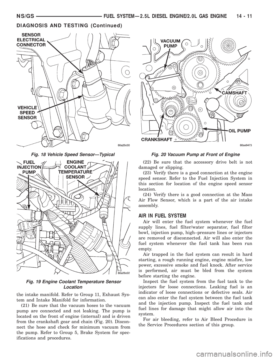
(21) Be sure that the vacuum hoses to the vacuum
pump are connected and not leaking. The pump is
located on the front of engine (internal) and is driven
from the crankshaft gear and chain (Fig. 20). Discon-
nect the hose and check for minimum vacuum from
the pump. Refer to Group 5, Brake System for spec-
ifications and procedures.(22) Be sure that the accessory drive belt is not
damaged or slipping.
(23) Verify there is a good connection at the engine
speed sensor. Refer to the Fuel Injection System in
this section for location of the engine speed sensor
location.
(24) Verify there is a good connection at the Mass
Air Flow Sensor, which is a part of the air intake
assembly.
AIR IN FUEL SYSTEM
Air will enter the fuel system whenever the fuel
supply lines, fuel filter/water separator, fuel filter
bowl, injection pump, high±pressure lines or injectors
are removed or disconnected. Air will also enter the
fuel system whenever the fuel tank has been run
empty.
Air trapped in the fuel system can result in hard
starting, a rough running engine, engine misfire, low
power, excessive smoke and fuel knock. After service
is performed, air must be bled from the system
before starting the engine.
Inspect the fuel system from the fuel tank to the
injectors for loose connections. Leaking fuel is an
indicator of loose connections or defective seals. Air
can also enter the fuel system between the fuel tank
and the injection pump. Inspect the fuel tank and
fuel lines for damage that might allow air into the
system.
For air bleeding, refer to Air Bleed Procedure in
the Service Procedures section of this group.
Fig. 18 Vehicle Speed SensorÐTypical
Fig. 19 Engine Coolant Temperature Sensor
Location
Fig. 20 Vacuum Pump at Front of Engine
NS/GSFUEL SYSTEMÐ2.5L DIESEL ENGINE/2.0L GAS ENGINE 14 - 11
DIAGNOSIS AND TESTING (Continued)
Page 1390 of 1938
(14) Gauge reading should be at 0.60 mm. If not,
the pump must be rotated for adjustment:
(a) Loosen the three injection pump mounting
nuts at the mounting flanges. These flanges are
equipped with slotted holes. The slotted holes are
used to rotate and position the injection pump for
fuel timing. Loosen the three nuts just enough to
rotate the pump.
(b) Rotate the pumpclockwise(as viewed from
front) until .60 mm is indicated on the dial indica-
tor gauge.
(c) Tighten the three pump mounting nuts to 30
N´m (22 ft. lbs.) torque.
(d) Recheck the dial indicator after tightening
the pump mounting nuts. Gauge should still be
reading 0.60 mm. Loosen pump mounting nuts and
readjust if necessary.
(15) Remove dial indicator and adapter tools.
(16) Install access plug and washer to rear of
injection pump.
(17) Install plug at timing gear cover.
(18) Remove dial indicator from valve stem.
(19) Install valve spring and keepers.
(20) Install rocker arm assembly and tighten nuts.
(21) Install and connect the four high±pressure
fuel lines to the fuel injection pump. Also connect
fuel lines at the fuel injectors. For procedures, refer
to High±Pressure Fuel Lines in this group.
(22) Install electrical connector at engine coolant
temperature sensor.
(23) Connect electrical connector at fuel shutdown
solenoid.(24) Connect the main engine wiring harness to
the glow plugs.
(25) Connect the fuel timing solenoid pigtail har-
ness to the engine wiring harness.
(26) Connect the overflow valve/banjo fitting (fuel
return line assembly). Replace copper gaskets before
installing.
(27) Connect the rubber fuel return and supply
hoses to metal lines at pump. Tighten hose clamps to
2 N´m (20 in. lbs.) torque.
(28) Install generator assembly.
(29) Install engine accessory drive belt. Refer to
Group 7, Cooling System for procedures.
(30) Install negative battery cable to battery.
(31) Start the engine and bring to normal operat-
ing temperature.
(32) Check for fuel leaks.
FUEL INJECTORS
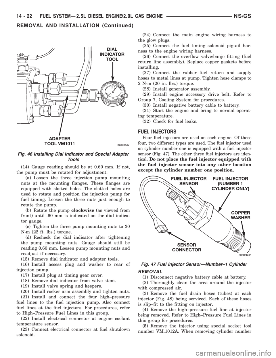
Four fuel injectors are used on each engine. Of these
four, two different types are used. The fuel injector used
on cylinder number one is equipped with a fuel injector
sensor (Fig. 47). The other three fuel injectors are iden-
tical.
Do not place the fuel injector equipped with
the fuel injector sensor into any other location
except the cylinder number one position.
REMOVAL
(1) Disconnect negative battery cable at battery.
(2) Thoroughly clean the area around the injector
with compressed air.
(3) Remove the fuel drain hoses (tubes) at each
injector (Fig. 48) being serviced. Each of these hoses
is slip±fit to the fitting on injector.
(4) Remove the high±pressure fuel line at injector
being removed. Refer to High±Pressure Fuel Lines in
this group for procedures.
(5) Remove the injector using special socket tool
number VM.1012A. When removing cylinder number
Fig. 46 Installing Dial Indicator and Special Adapter
Tools
Fig. 47 Fuel Injector SensorÐNumber±1 Cylinder
14 - 22 FUEL SYSTEMÐ2.5L DIESEL ENGINE/2.0L GAS ENGINENS/GS
REMOVAL AND INSTALLATION (Continued)
Page 1416 of 1938
The speed sensor generates 8 pulses per sensor
revolution. These signals, in conjunction with a
closed throttle signal from the throttle position sen-
sor, indicate a closed throttle deceleration to the
PCM. When the vehicle is stopped at idle, a closed
throttle signal is received by the PCM (but a speed
sensor signal is not received).
In addition to determining distance and vehicle
speed, the output from the sensor is used to control
speed control operation.
SPEED CONTROLÐPCM INPUTS
The speed control system provides five separate
inputs to the PCM; On/Off, Set, Resume/Accel, Cancel,
and Decel.. The On/Off input informs the PCM that
the speed control system has been activated. The Set
input informs the PCM that a fixed vehicle speed has
been selected. The Resume input indicates to the PCM
that the previous fixed speed is requested.
Speed control operation will start at 50 km/h±142
km/h (35±85 mph). The upper range of operation is
not restricted by vehicle speed. Inputs that affect
speed control operation are vehicle speed sensor and
throttle position sensor.
Refer to Group 8H for further speed control infor-
mation.
DIESEL PCM RELAYÐPCM INPUT
A 12 volt signal at this input indicates to the PCM
that the Diesel relay has been activated. The Diesel
relay is located in the PDC. The PDC is located next
to the battery in the engine compartment. For the
location of the relay within the PDC, refer to label on
PDC cover.
This input is used only to sense that the Diesel
relay is energized. If the PCM does not see 12 volts +
at this input when the Diesel relay should be acti-
vated, it will set a Diagnostic Trouble Code (DTC).
FIVE VOLT POWERÐPCM OUTPUT
This circuit supplies approximately 5 volts to
power the Accelerator Pedal Postion Sensor, Mass Air
Flow Sensor, and A/C Pressure Sensor.
ENGINE COOLANT GAUGEÐPCM OUTPUT
Refer to the Instrument Panel and Gauges group
for additional information.
ENGINE OIL PRESSURE GAUGEÐPCM OUTPUT
Refer to the Instrument Panel and Gauges group
for additional information.
GLOW PLUG LAMPÐPCM OUTPUT
The Glow Plug lamp (malfunction indicator lamp)
illuminates on the message center each time the igni-
tion (key) switch is turned on. It will stay on for
about two seconds as a bulb test.If the PCM receives an incorrect signal, or no sig-
nal from certain sensors or components, the lamp
BLINKS. This is a warning that the PCM has
recorded a system or sensor malfunction. It signals
an immediate need for service. There are only 5
HARD faults that can turn on this lamp to make it
blink.
SPEED CONTROLÐPCM OUTPUTS
These two circuits control the fuel quantity actua-
tor to regulate vehicle speed. Refer to Group 8H for
Speed Control information.
AIR CONDITIONING RELAYÐPCM OUTPUT
This circuit controls a ground signal for operation
of the A/C clutch relay. Also refer to Air Conditioning
(A/C) ControlsÐPCM Input for additional informa-
tion.
The A/C relay is located in the Power Distribution
Center (PDC). The PDC is located next to the battery
in the engine compartment. For the location of the
relay within the PDC, refer to label on PDC cover.
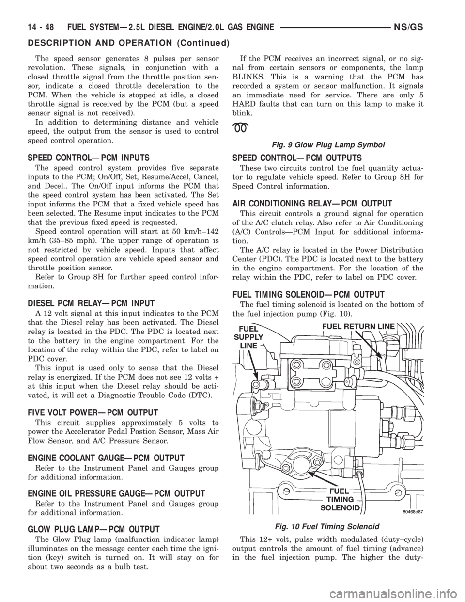
FUEL TIMING SOLENOIDÐPCM OUTPUT
The fuel timing solenoid is located on the bottom of
the fuel injection pump (Fig. 10).
This 12+ volt, pulse width modulated (duty±cycle)
output controls the amount of fuel timing (advance)
in the fuel injection pump. The higher the duty-
Fig. 9 Glow Plug Lamp Symbol
Fig. 10 Fuel Timing Solenoid
14 - 48 FUEL SYSTEMÐ2.5L DIESEL ENGINE/2.0L GAS ENGINENS/GS
DESCRIPTION AND OPERATION (Continued)
Page 1545 of 1938

41TE AUTOMATIC TRANSAXLE
INDEX
page page
GENERAL INFORMATION
41TE FOUR SPEED AUTOMATIC TRANSAXLE . 71
FLUID LEVEL AND CONDITION............. 72
SELECTION OF LUBRICANT............... 72
SPECIAL ADDITIVES..................... 72
DESCRIPTION AND OPERATION
ADAPTIVE CONTROLS................... 73
CLUTCH AND GEAR..................... 72
ELECTRONICS......................... 73
GEARSHIFT AND PARKING LOCK CONTROLS . 74
HYDRAULICS........................... 73
ON-BOARD DIAGNOSTICS................ 74
SENSORS............................. 73
SHIFT POSITION INDICATOR.............. 74
SOLENOIDS............................ 73
TORQUE MANAGEMENT.................. 74
TRANSMISSION CONTROL MODULE........ 74
TRANSMISSION RANGE SENSOR........... 74
DIAGNOSIS AND TESTING
41TE TRANSAXLE GENERAL DIAGNOSIS..... 75
CLUTCH AIR PRESSURE TESTS............ 77
FLUID LEAKAGE-TORQUE CONVERTER
HOUSING AREA....................... 78
HYDRAULIC PRESSURE TESTS............ 75
ROAD TEST............................ 75
SHIFT POSITION INDICATOR.............. 78
SERVICE PROCEDURES
ALUMINUM THREAD REPAIR.............. 81
FLUID AND FILTER CHANGE............... 79
FLUID DRAIN AND REFILL................. 81
FLUSHING COOLERS AND TUBES.......... 81OIL PUMP VOLUME CHECK............... 82
PINION FACTOR PROCEDURE............. 83
TRANSAXLE QUICK LEARN PROCEDURE.... 82
REMOVAL AND INSTALLATION
GEARSHIFT CABLE...................... 83
MANUAL VALVE LEVER (SHIFT LEVER)...... 84
OIL PUMP SEAL......................... 92
SOLENOID ASSEMBLY-REPLACE........... 85
SPEED SENSOR-INPUT................... 86
SPEED SENSOR-OUTPUT................. 86
TRANSAXLE........................... 89
TRANSMISSION CONTROL MODULE........ 87
TRANSMISSION RANGE SENSOR........... 85
VALVE BODY........................... 88
DISASSEMBLY AND ASSEMBLY
DIFFERENTIAL REPAIR.................. 139
INPUT CLUTCHES-RECONDITION.......... 110
TRANSAXLE ASSEMBLE................. 122
TRANSAXLE DISASSEMBLE............... 95
VALVE BODY RECONDITION............... 92
CLEANING AND INSPECTION
CLEANING VALVE BODY................. 144
ADJUSTMENTS
GEARSHIFT CABLE ADJUSTMENT......... 144
SCHEMATICS AND DIAGRAMS
41TE TRANSAXLE HYDRAULIC SCHEMATICS . 145
SPECIFICATIONS
41TE AUTOMATIC TRANSAXLE............ 158
41TE TORQUE SPECIFICATIONS.......... 158
SPECIAL TOOLS
41TE AUTOMATIC TRANSAXLE............ 159
GENERAL INFORMATION
41TE FOUR SPEED AUTOMATIC TRANSAXLE
The 41TE four-speed FWD transaxle uses fully-
adaptive controls. Adaptive controls are those which
perform their functions based on real-time feedback
sensor information. The transaxle uses hydraulically
applied clutches to shift a planetary gear train.
TRANSAXLE IDENTIFICATION
The 41TE transaxle identification code is printed
on a label. The label is located on the transaxle case
next to the solenoid assembly (Fig. 1).
Fig. 1 Identification Tag Location
NSTRANSAXLE AND POWER TRANSFER UNIT 21 - 71
Page 1548 of 1938
TORQUE MANAGEMENT
Most 41TE transaxles utilize torque management.
Torque management is a unique function of the Pow-
ertrain Control Module (PCM). The PCM receives
output signals from the Transmission Control Module
(TCM) and many various engine sensors. The PCM
evaluates these signals and decides if it is necessary
to decrease the output of the engine's torque. This
reduction in torque does not interfere with the nor-
mal operation of the vehicle. This reduction in torque
will prolong the life of the drivetrain components.
Torque reduction is not noticeable in normal driving
functions. The torque reduction function shuts off
above 16 MPH.
ON-BOARD DIAGNOSTICS
This vehicle utilizes a diagnostic system called
OBDII. The powertrain control module communicates
with the Transmission Control Module. Whenever
the transaxle sets a fault in the Transmission Con-
trol Module (dependent on which fault is set), the
powertrain control module will turn on a MIL (Mal-
function Indicator Lamp) on the instrument cluster.
By reading the code in the powertrain control module
it will tell you where the fault occurred. If the fault
occurred in the transaxle, the controller will read a
CODE 45.For further information regarding OBDII,
refer to Group 25, Emission Systems.
These controls provide comprehensive, on-board
transaxle diagnostics. The information available can
aid in transaxle diagnosis. For example, apply ele-
ment buildup rate indicates solenoid performance.
Also included are self diagnostic functions. Self diag-
nostics allow the technician to test the condition of
the electronic controls. The Transmission Control
Module continuously monitors its critical functions. It
also records any malfunctions, and the number of
engine starts since the last malfunction. This allows
the technician to use the information in the event of
a customer complaint.
TRANSMISSION CONTROL MODULE
Do not interchange Transmission Control Modules
with previous year transmission control modules. If a
same year TCM is being used from a different vehi-
cle, the following procedures must be performed:
²Quick Learn Procedure
²Electronic Pinion Factor Procedure
The Transmission Control Module is located on the
right inner fender panel, in the engine compartment.
It is held in place by four mounting screws.NOTE: If the Transmission Control Module has
been replaced, the following procedures must be
performed:
²Quick Learn Procedure: This procedure will
allow the transmission control module to learn the
characteristics of the vehicle.
²Electronic Pinion Factor Procedure: This proce-
dure will reprogram the TCM to compensate for dif-
ferent tire sizes and final drive ratios.
GEARSHIFT AND PARKING LOCK CONTROLS
The transaxle is controlled by a lever type gear-
shift incorporated within the steering column. The
control has six selector lever positions: P (park), R
(reverse), N (neutral), and D (drive), 2 (second), and
1 (first). The parking lock is applied by moving the
selector lever past a gate to the P position.Do not
apply the parking lock until the vehicle has
stopped; otherwise, a severe ratchet noise will
occur.
TRANSMISSION RANGE SENSOR
The 41TE transaxle is equipped with a transmis-
sion range sensor that is located on top of the valve
body. This sensor will allow for accurate transmission
gear position measurement.
To service the transmission range sensor (TRS),
you must remove the valve body. For repair proce-
dures, refer to the Removal and Installation section
within this group.
Also located within the TRS is a transmission tem-
perature sensor. This sensor is used to measure the
transmission fluid sump temperature. The transmis-
sion temperature sensor is serviced with the TRS as
a unit.
SHIFT POSITION INDICATOR
The shifter position indicator is located in the
instrument cluster. The shifter position indicator out-
lines with a box the gear position the transaxle man-
ual valve lever is in.
The transmission range sensor (located on the
valvebody) sends a signal to the TCM on the position
of the transaxle manual valve lever. The TCM
receives the switch signal and processes the data.
The TCM sends the Shift Lever Position (SLP) infor-
mation to the BCM via the CCD bus. The BCM then
outlines with a box the appropriate shifter position
indicator in the instrument cluster.
To replace the shifter position indicator, refer to
Group 8E, Instrument Panel And Gauges.
21 - 74 TRANSAXLE AND POWER TRANSFER UNITNS
DESCRIPTION AND OPERATION (Continued)
Page 1553 of 1938
If a problem arises with the shifter position indica-
tor, consult the following chart for diagnostic infor-
mation. If the malfunction cannot be corrected using
the chart, consult the proper diagnostic manual.
To replace the shifter position indicator, refer to
Group 8E, Instrument Panel And Gauges.SERVICE PROCEDURES
FLUID AND FILTER CHANGE
When the factory fill fluid is changed, only fluids
labeled MOPARtATF PLUS 3 (Automatic Transmis-
sion fluid) Type 7176 should be used.
If the transaxle is disassembled for any reason, the
fluid and filter should be changed.
30,000 MILE TRANSAXLE OIL CHANGE
When a vehicle attains 30,000 miles on its odome-
ter it is recommended that the transaxle oil be
changed. To change the oil, use the procedure that
follows:
It is recommended that a transaxle fluid exchanger
(ATF 2000+ or equivalent) be used to replace the
used fluid in the transaxle. If a fluid exchanger is not
available use a fluid suction pump (Vaculayor equiv-
alent) to draw the fluid out of the dipstick tube. If a
fluid suction pump is not available remove the oil
pan and drain the fluid.
CAUTION: Chrysler Corporation does not recom-
mend using any fluid exchanger that introduces
additives into the transaxle.
TRANSAXLE FLUID EXCHANGER METHOD
(1) To perform the transaxle fluid exchange, the
transaxle must be at operating temperature. Drive
the vehicle till it reaches full operating temperature.
(2) Verify that the fill tank on the transaxle fluid
exchanger (ATF 2000+ or equivalent) is clean and
dry.
(3) Fill the tank to the recommended fill capacity
with Mopar ATF Plus 3 Type 7176.
(4) Hookup the vehicle to the machine following
the manufacturers instructions. Perform the
exchange procedure following the instructions pro-
vided with the machine.
(5) Once machine has completed the fluid
exchange. Check the fluid level and condition and fill
to proper level with Mopar ATF Plus 3 Type 7176.
NOTE: Verify that the transaxle cooler lines are
tightened to proper specifications. Cooler line
torque specification is 2 N´m (18 in. lbs.).
CONDITION POSSIBLE CAUSE
ALL PRND3L DISPLAY
LIGHTS9ON9IN P&N
GEAR POSITIONS1.Check wiring and
connectors
2. Faulty trans. range
sensor
3. Faulty manual lever
ALL DISPLAY LIGHTS
9ON9IN ALL GEAR
POSITIONS1. Check wiring &
connectors
2. Faulty trans. range
sensor
3. Faulty manual lever
4. CCD communication
malfunction
5. Check oil level
ALL DISPLAY LIGHTS
9OFF91. Normal transient
condition between P&R
and R&N gear positions
2. Check shift lever
linkage
3. Body controller
malfunction
4. Check wiring and
connectors
5. Faulty cluster
ALL DISPLAY LIGHTS
9OFF9ACCOMPANIED
BY A9NO BUS9
MESSAGE1. CCD communication
malfunction
DISPLAY LIGHTS OUT
OF SEQUENCE WITH
SHIFT LEVER1. Check wiring and
connectors
2. Faulty trans. range
sensor
3. Faulty manual lever
4. CCD communication
malfunction
NSTRANSAXLE AND POWER TRANSFER UNIT 21 - 79
DIAGNOSIS AND TESTING (Continued)
Page 1555 of 1938
(11) Recheck the fluid level after the transaxle is
at normal operating temperature. The level should be
in the HOT range. Drive the vehicle a minimum of
10 miles.
(12) Raise the vehicle on the hoist.
(13) Remove the pan and clean all sealant from
the pan and transaxle mating surfaces. Clean the
magnet and the inside of the pan.
(14) Separate the filter from the valve body to
allow additional fluid to drain from the transaxle.
Inspect the filter O-ring for any damage and replace
as necessary.
(15) After the transaxle has stopped draining,
reinstall the filter and O-ring.
(16) Apply a 1/8 inch bead of Mopar RTV Sealant
to the mounting flange of the transaxle oil pan.
Apply RTV Sealant to the underside of the attaching
bolts. Attach the oil pan to the transaxle. Tighten the
bolts to 19 N´m (165 in. lbs.).
(17) Lower the vehicle and add 4 Quarts of Mopar
ATF Plus 3 Type 7176 transaxle fluid.
(18) Start the engine and allow it to idle for a min-
imum of one minute. With the parking brake applied,
press your foot on the service brake and cycle the
transaxle from park to all gear positions ending in
neutral or park.
(19) Check the transaxle fluid level and add an
appropriate amount to bring the transaxle fluid level
to 3mm (1/8 in.) below the ADD mark on the dip-
stick.
(20) Recheck the fluid level after the transaxle is
at normal operating temperature. The level should be
in the HOT range.
FLUID DRAIN AND REFILL
(1) Raise vehicle on a hoist (See Group 0, Lubrica-
tion). Place a drain container with a large opening,
under transaxle oil pan.
(2) Loosen pan bolts and tap the pan at one corner
to break it loose allowing fluid to drain, then remove
the oil pan.
(3) Install a new filter and O-ring on bottom of the
valve body.
(4) Clean the oil pan and magnet. Reinstall pan
using new MOPARtRTV sealant. Tighten oil pan
bolts to 19 N´m (165 in. lbs.).
(5) Pour four quarts of MOPARtATF PLUS 3
(Automatic Transmission Fluid) Type 7176 through
the fill tube.
(6) Start engine and allow to idle for at least one
minute. Then, with parking and service brakes
applied, move selector lever momentarily to each
position, ending in the park or neutral position.(7) Add sufficient fluid to bring level to 1/8 inch
below the ADD mark.
CAUTION: Do not overfill transaxle. Do not add oil
if level is between: Lower holes for warm oil
(100ÉF). Upper holes for hot oil (180ÉF).
(8) Recheck fluid level after transaxle is at normal
operating temperature. The level should be in the
HOT region (Fig. 5).
(9) To prevent dirt from entering transaxle, make
certain that dipstick is seated into the dipstick fill
tube.
ALUMINUM THREAD REPAIR
Damaged or worn threads in the aluminum tran-
saxle case and valve body can be repaired by the use
of Heli-Coils, or equivalent. This repair consists of
drilling out the worn-out damaged threads. Then tap
the hole with a special Heli-Coil tap, or equivalent,
and installing a Heli-Coil insert, or equivalent, into
the hole. This brings the hole back to its original
thread size.
Heli-Coil, or equivalent, tools and inserts are
readily available from most automotive parts suppli-
ers.
FLUSHING COOLERS AND TUBES
When a transaxle failure has contaminated the
fluid, the oil cooler(s) must be flushed. The cooler
bypass valve in the transaxle must be replaced also.
The torque converter must also be replaced with an
exchange unit. This will insure that metal particles
or sludged oil are not later transferred back into the
reconditioned (or replaced) transaxle.
The recommended procedure for flushing the tran-
saxle cooler is to use Tool 6906A Cooler Flusher.
Fig. 5 Oil Level Indicator
NSTRANSAXLE AND POWER TRANSFER UNIT 21 - 81
SERVICE PROCEDURES (Continued)