1996 CHRYSLER VOYAGER service indicator
[x] Cancel search: service indicatorPage 934 of 1938

(LHD) MESSAGE CENTER
* DIESEL WAIT-TO START WARNING LAMP DRIVER G85 20OR/BK * 7
BLUE
7 1
136
G69 22BK/OR M1 20PK
R41 18BK/TN V23 18BR/PK G9 20GY/BK
G6 22GY G3 20BK/PK G2 22VT
G19 20LG/OR L62 18BR/RD Z1 20BK
L63 18DG/RD L34 20RD/OR
13 12 11 10 9 8 7 6 5 4
3 2 1 CAV VTSS INDICATOR LAMP DRIVER
FUSED B (+)
AIRBAG WARNING LAMP DRIVER FUSED IGNITION (ST-RUN) RED BRAKE WARNING LAMP DRIVER
ENGINE OIL PRESSURE SWITCH SENSE SERVICE ENGINE SOON INDICATOR LAMP DRIVER ENGINE TEMPERATURE WARNING LAMP DRIVER
ABS WARNING LAMP DRIVER RIGHT TURN SIGNAL GROUND
LEFT TURN SIGNAL FUSED HIGH BEAM RELAY OUTPUT CIRCUIT
FUNCTION
SWITCH MEMORY SET
BLUE564
1 2 3
P23 20PK/RD P22 20PK/BK P24 20PK/WT Z1 20BK
6 5 4 3 2
1 CAV MEMORY NO. 2 MEMORY SET MEMORY NO. 1 GROUND - - CIRCUIT
- - FUNCTION
MODULE - C3 MEMORY SEAT/MIRROR
21 10
11 NATURAL
1
P29 20BR/WT P25 22VT/RD P47 22LB P40 22GY/LB P15 22YL/LB
P11 22YL/WT P19 22YL/LG P9 20RD
P28 20BR/RD P26 22BR P27 22LB/RD P48 22GY/WT P17 22RD/LB P13 22RD/WT
P21 22RD/LG
21 20 19
18 17 16
15 14 13
12 11 10 9 8 7
6
5 4 3
2 1 CAV 6 VOLT SUPPLY SEAT HORIZONTAL POSITION SENSE SEAT RECLINER POSITION SENSE SEAT RECLINER (FORWARD) SEAT HORIZONTAL (FORWARD) SEAT REAR VERTICAL (UP) SEAT FRONT VERTICAL (UP)
FUSED B (+) SEAT POSITION SENSE COMMON SEAT FRONT VERTICAL POSITION SENSE SEAT REAR VERTICAL POSITION SENSE SEAT RECLINER (REARWARD) SEAT HORIZONTAL (REARWARD)
SEAT REAR VERTICAL (DOWN)
SEAT FRONT VERTICAL (DOWN)
- - - - - - CIRCUIT
- - - - - - - FUNCTION
8W - 80 - 58 8W-80 CONNECTOR PIN-OUTSNS/GS
J988W-3NSGS8058
Page 935 of 1938

SWITCH MULTI-FUNCTION
8 127BLACK
1
L324 22WT/LG V10 20BR
L94 20OR/WT L93 22PK Z1 18BK
F1 20DB V52 20DG//YL V16 20WT
L305 22LB/WT L302 22LB/YL L91 22DB/PK
12 11 10 9 8 7
6
5 4 3 2 1 CAV HIGH BEAM RELAY CONTROL
FRONT WASHER MOTOR CONTROL LOW BEAM RELAY CONTROL HIGH/LOW BEAM RELAY CONTROL
GROUND FUSED B(+) WIPER MUX SIGNAL
HIGH SPEED RELAY DRIVER RIGHT TURN SIGNAL SENSE LEFT TURN SIGNAL SENSE COMBO FLASHER SWITCHED GROUND
- CIRCUIT
- FUNCTION
ACTUATOR MODE DOOR
5BLACK1
C35 20DG/YL C57 20DB/GY C37 20YL
C26 20PK/DB
C34 20DB/WT
5 4
3 2 1 CAV MODE DOOR DRIVER SENSOR GROUND MODE DOOR FEEDBACK SIGNAL
5 VOLT SUPPLY DOOR COMMON CIRCUIT
FUNCTION
FUSED RIGHT HIGH BEAM OUTPUT L34 20RD/OR7 131 6ENGINE TEMPERATURE WARNING LAMP DRIVER CIRCUIT FUNCTION
CAV
G2 22VT
1
2G19 20LG/OR
3L63 18DG/RD LEFT TURN SIGNAL
6L62 18BR/RD RIGHT TURN SIGNALSGROUND Z1 20BK
54
G69 22BK/OR
7
8M1 20PK
9R41 18BK/OR
V23 18BR/PK
10
13G3 20BK/PKENGINE OIL PRESSURE SWITCH SENSE G6 22GY
12G9 20GY/BK RED BRAKE WARNING LAMP DRIVER
11ABS WARNING LAMP DRIVER
FUSED B(+)
FUSED IGNITION (ST-RUN)
(RHD) MESSAGE CENTER
VTSS INDICATOR LAMP DRIVER
AIRBAG WARNING LAMP DRIVER
SERVICE ENGINE SOON INDICATOR LAMP DRIVER
NS/GS8W-80 CONNECTOR PIN-OUTS 8W - 80 - 59
NSGS8059J988W-3
Page 947 of 1938

MODULE - C1CONTROL POWERTRAIN
- -
K90 18TN ENGINE STARTER MOTOR RELAY CONTROL
C103 18DG/LB A/C SWITCH SIGNALKNOCK SENSOR SIGNAL K42 18DB/LG- - BLACK
10 20 30 40
1 11 21 31
K35 18GY/YL K1 18DG/RD K22 18OR/DB K44 18TN/YL K24 18GY/BK K41 18BK/DG K2 18TN/BK G3 18BK/PK F87 18WT/BK K12 18TN/WT K14 18LB/BR
K38 18GY K58 18BR/DB K11 18WT/DB K19 18GY/RD Z12 18BK/TN K20 18DG K13 18YL/WT
A142 18DG/OR V32 18YL/RD K17 18DB/TN K18 18RD/YL
40 39 38
37 36 35
34 33 32
31
30 29 28
27 26 25 24 23
22 21 20
19 18 17
16 15 14
13 12 11
10 9 8
7 6 5
4 3 2
1 CAV EGR SOLENOID CONTROL MANIFOLD ABSOLUTE PRESSURE SENSOR SIGNAL THROTTLE POSITION SENSOR SIGNAL CAMSHAFT POSITION SENSOR SIGNAL CRANKSHAFT POSITION SENSOR SIGNAL HEATED OXYGEN SENSOR SIGNAL ENGINE COOLANT TEMPERATURE SENSOR SIGNAL SERVICE ENGINE SOON INDICATOR LAMP DRIVER FUSED IGNITION SWITCH OUTPUT (ST-RUN) INJECTOR NO. 2 DRIVER INJECTOR NO. 4 DRIVER
INJECTOR NO. 5 DRIVER (3.3L/3.8L) INJECTOR NO. 6 DRIVER (3.3L/3.8L) INJECTOR NO. 1 DRIVER IGNITION COIL NO. 1 DRIVER GROUND GENERATOR FIELD DRIVER INJECTOR NO. 3 DRIVER
AUTOMATIC SHUT DOWN RELAY OUTPUT SPEED CONTROL ON/OFF SWITCH SENSE IGNITION COIL NO. 2 DRIVER IGNITION COIL NO. 3 DRIVER (3.3L/3.8L)
- - - - - - -
- - - - - CIRCUIT
- - - - - - -
- - - - - FUNCTION
K21 18BK/RD* INTAKE AIR TEMPERATURE SENSOR SIGNAL
* 2.0L
NS/GS8W-80 CONNECTOR PIN-OUTS 8W - 80 - 71
NSGS8071J988W-3
Page 1057 of 1938
ENGINE DIAGNOSIS
INDEX
page page
DIAGNOSIS AND TESTING
CYLINDER COMBUSTION
PRESSURE LEAKAGE TEST.............. 8
CYLINDER COMPRESSION PRESSURE TEST . . 7
ENGINE DIAGNOSISÐMECHANICAL......... 12
ENGINE DIAGNOSISÐPERFORMANCE...... 10GENERAL INFORMATION.................. 7
INSPECTION
(ENGINE OIL LEAKS IN GENERAL)......... 8
INTAKE MANIFOLD LEAKAGE DIAGNOSIS..... 7
LASH ADJUSTER (TAPPET)
NOISE DIAGNOSIS...................... 8
DIAGNOSIS AND TESTING
GENERAL INFORMATION
Engine diagnosis is helpful in determining the
causes of malfunctions.
These malfunctions may be classified as either
mechanical (e.g., a strange noise), or performance
(e.g., engine idles rough and stalls).
Refer to the Service DiagnosisÐMechanical Chart
and the Service DiagnosisÐPerformance Chart, for
possible causes and corrections of malfunctions. Refer
to Group 14, Fuel System, for the fuel system diag-
nosis.
Additional tests and diagnostic procedures may be
necessary for specific engine malfunctions that can-
not be isolated with the Service Diagnosis charts.
Information concerning additional tests and diagno-
sis is provided within the following:
²Cylinder Compression Pressure Test
²Cylinder Combustion Pressure Leakage Test
²Engine Cylinder Head Gasket Failure Diagnosis
²Intake Manifold Leakage Diagnosis
INTAKE MANIFOLD LEAKAGE DIAGNOSIS
An intake manifold air leak is characterized by
lower than normal manifold vacuum. Also, one or
more cylinders may not be functioning.
WARNING: USE EXTREME CAUTION WHEN THE
ENGINE IS OPERATING. DO NOT STAND IN A
DIRECT LINE WITH THE FAN. DO NOT PUT YOUR
HANDS NEAR THE PULLEYS, BELTS OR THE FAN.
DO NOT WEAR LOOSE CLOTHING.
(1) Start the engine.
(2) Spray a small stream of water (Spray Bottle) at
the suspected leak area.
(3) If a change in RPM'S, the area of the suspected
leak has been found.
(4) Repair as required.
CYLINDER COMPRESSION PRESSURE TEST
The results of a cylinder compression pressure test
can be utilized to diagnose several engine malfunc-
tions.
Ensure the battery is completely charged and the
engine starter motor is in good operating condition.
Otherwise the indicated compression pressures may
not be valid for diagnosis purposes.
(1) Check engine oil level and add oil if necessary.
(2) Drive the vehicle until engine reaches normal
operating temperature. Select a route free from traf-
fic and other forms of congestion, observe all traffic
laws, and accelerate through the gears several times
briskly.
(3) Remove all spark plugs from engine. As spark
plugs are being removed, check electrodes for abnor-
mal firing indicators fouled, hot, oily, etc. Record cyl-
inder number of spark plug for future reference.
(4) Disconnect coil wire from distributor and
secure to good ground to prevent a spark from start-
ing a fire (Conventional Ignition System). For Direct
Ignition System DIS disconnect the coil connector.
(5) Be sure throttle blade is fully open during the
compression check.
(6) Insert compression gage adaptor into the #1
spark plug hole in cylinder head. Crank engine until
maximum pressure is reached on gage. Record this
pressure as #1 cylinder pressure.
(7) Repeat the previous step for all remaining cyl-
inders.
(8) Compression should not be less than (689kPa)
100 psi and not vary more than 25 percent from cyl-
inder to cylinder.
(9) If one or more cylinders have abnormally low
compression pressures, repeat the compression test.
(10) If the same cylinder or cylinders repeat an
abnormally low reading on the second compression
test, it could indicate the existence of a problem in
the cylinder in question.The recommended com-
pression pressures are to be used only as a
guide to diagnosing engine problems. An engine
should not be disassembled to determine the
NSENGINE 9 - 7
Page 1070 of 1938
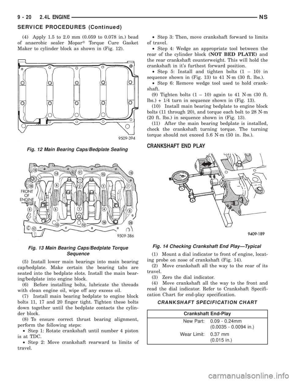
(4) Apply 1.5 to 2.0 mm (0.059 to 0.078 in.) bead
of anaerobic sealer MopartTorque Cure Gasket
Maker to cylinder block as shown in (Fig. 12).
(5) Install lower main bearings into main bearing
cap/bedplate. Make certain the bearing tabs are
seated into the bedplate slots. Install the main bear-
ing/bedplate into engine block.
(6) Before installing bolts, lubricate the threads
with clean engine oil, wipe off any excess oil.
(7) Install main bearing bedplate to engine block
bolts 11, 17 and 20 finger tight. Tighten these bolts
down together until the bedplate contacts the cylin-
der block.
(8) To ensure correct thrust bearing alignment,
perform the following steps:
²Step 1: Rotate crankshaft until number 4 piston
is at TDC.
²Step 2: Move crankshaft rearward to limits of
travel.²Step 3: Then, move crankshaft forward to limits
of travel.
²Step 4: Wedge an appropriate tool between the
rear of the cylinder block(NOT BED PLATE)and
the rear crankshaft counterweight. This will hold the
crankshaft in it's furthest forward position.
²Step 5: Install and tighten bolts (1 ± 10) in
sequence shown in (Fig. 13) to 41 N´m (30 ft. lbs.).
²Step 6: Remove wedge tool used to hold crank-
shaft.
(9) Tighten bolts (1 ± 10) again to 41 N´m (30 ft.
lbs.) + 1/4 turn in sequence shown in (Fig. 13).
(10) Install main bearing bedplate to engine block
bolts (11 through 20), and torque each bolt to 28 N´m
(20 ft. lbs.) in sequence shown in (Fig. 13).
(11) After the main bearing bedplate is installed,
check the crankshaft turning torque. The turning
torque should not exceed 5.6 N´m (50 in. lbs.).
CRANKSHAFT END PLAY
(1) Mount a dial indicator to front of engine, locat-
ing probe on nose of crankshaft (Fig. 14).
(2) Move crankshaft all the way to the rear of its
travel.
(3) Zero the dial indicator.
(4) Move crankshaft all the way to the front and
read the dial indicator. Refer to Crankshaft Specifi-
cation Chart for end-play specification.
Fig. 12 Main Bearing Caps/Bedplate Sealing
Fig. 13 Main Bearing Caps/Bedplate Torque
SequenceFig. 14 Checking Crankshaft End PlayÐTypical
CRANKSHAFT SPECIFICATION CHART
Crankshaft End-Play
New Part: 0.09 - 0.24mm
(0.0035 - 0.0094 in.)
Wear Limit: 0.37 mm
(0.015 in.)
9 - 20 2.4L ENGINENS
SERVICE PROCEDURES (Continued)
Page 1072 of 1938
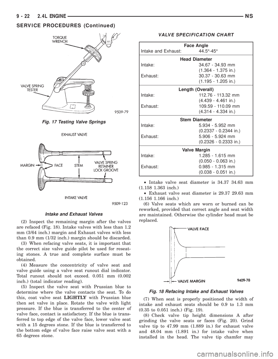
(2) Inspect the remaining margin after the valves
are refaced (Fig. 18). Intake valves with less than 1.2
mm (3/64 inch.) margin and Exhaust valves with less
than 0.9 mm (1/32 inch.) margin should be discarded.
(3) When refacing valve seats, it is important that
the correct size valve guide pilot be used for reseat-
ing stones. A true and complete surface must be
obtained.
(4) Measure the concentricity of valve seat and
valve guide using a valve seat runout dial indicator.
Total runout should not exceed. 0.051 mm (0.002
inch.) (total indicator reading).
(5) Inspect the valve seat with Prussian blue to
determine where the valve contacts the seat. To do
this, coat valve seatLIGHTLYwith Prussian blue
then set valve in place. Rotate the valve with light
pressure. If the blue is transferred to the center of
valve face, contact is satisfactory. If the blue is trans-
ferred to top edge of the valve face, lower valve seat
with a 15 degrees stone. If the blue is transferred to
the bottom edge of valve face raise valve seat with a
65 degrees stone.²Intake valve seat diameter is 34.37 34.63 mm
(1.158 1.363 inch.)
²Exhaust valve seat diameter is 29.37 29.63 mm
(1.156 1.166 inch.)
(6) Valve seats which are worn or burned can be
reworked, provided that correct angle and seat width
are maintained. Otherwise the cylinder head must be
replaced.
(7) When seat is properly positioned the width of
intake and exhaust seats should be 0.9 to 1.3 mm
(0.35 to 0.051 inch.) (Fig. 19).
(8) Check valve tip height dimensions A after
grinding the valve seats or faces (Fig. 20). Grind
valve tip to 47.99 mm (1.889 in.) for exhaust valve
and 48.04 mm (1.891 in.) for intake valve when
installed in the head. The valve tip chamfer may
Fig. 17 Testing Valve Springs
Intake and Exhaust Valves
VALVE SPECIFICATION CHART
Face Angle
Intake and Exhaust: 44.5É-45É
Head Diameter
Intake: 34.67 - 34.93 mm
(1.364 - 1.375 in.)
Exhaust: 30.37 - 30.63 mm
(1.195 - 1.205 in.)
Length (Overall)
Intake: 112.76 - 113.32 mm
(4.439 - 4.461 in.)
Exhaust: 109.59 - 110.09 mm
(4.314 - 4.334 in.)
Stem Diameter
Intake: 5.934 - 5.952 mm
(0.2337 - 0.2344 in.)
Exhaust: 5.906 - 5.924 mm
(0.2326 - 0.2333 in.)
Valve Margin
Intake: 1.285 - 1.615 mm
(0.050 - 0.063 in.)
Exhaust: 0.985 - 1.315 mm
(0.038 - 0.051 in.)
Fig. 18 Refacing Intake and Exhaust Valves
9 - 22 2.4L ENGINENS
SERVICE PROCEDURES (Continued)
Page 1079 of 1938
(5) Identify the camshafts before removing from
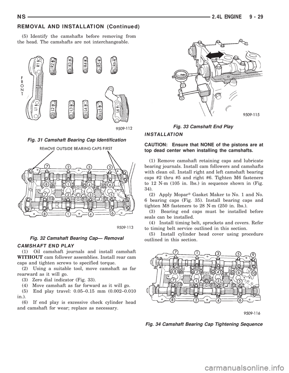
the head. The camshafts are not interchangeable.
CAMSHAFT END PLAY
(1) Oil camshaft journals and install camshaft
WITHOUTcam follower assemblies. Install rear cam
caps and tighten screws to specified torque.
(2) Using a suitable tool, move camshaft as far
rearward as it will go.
(3) Zero dial indicator (Fig. 33).
(4) Move camshaft as far forward as it will go.
(5) End play travel: 0.05±0.15 mm (0.002±0.010
in.).
(6) If end play is excessive check cylinder head
and camshaft for wear; replace as necessary.
INSTALLATION
CAUTION: Ensure that NONE of the pistons are at
top dead center when installing the camshafts.
(1) Remove camshaft retaining caps and lubricate
bearing journals. Install cam followers and camshafts
with clean oil. Install right and left camshaft bearing
caps #2 thru #5 and right #6. Tighten M6 fasteners
to 12 N´m (105 in. lbs.) in sequence shown in (Fig.
34).
(2) Apply MopartGasket Maker to No. 1 and No.
6 bearing caps (Fig. 35). Install bearing caps and
tighten M8 fasteners to 28 N´m (250 in. lbs.).
(3) Bearing end caps must be installed before
seals can be installed.
(4) Install timing belt, sprockets and covers. Refer
to timing belt service outlined in this section.
(5) Install cylinder head cover using procedure
outlined in this section.Fig. 31 Camshaft Bearing Cap Identification
Fig. 32 Camshaft Bearing CapÐ Removal
Fig. 33 Camshaft End Play
Fig. 34 Camshaft Bearing Cap Tightening Sequence
NS2.4L ENGINE 9 - 29
REMOVAL AND INSTALLATION (Continued)
Page 1115 of 1938
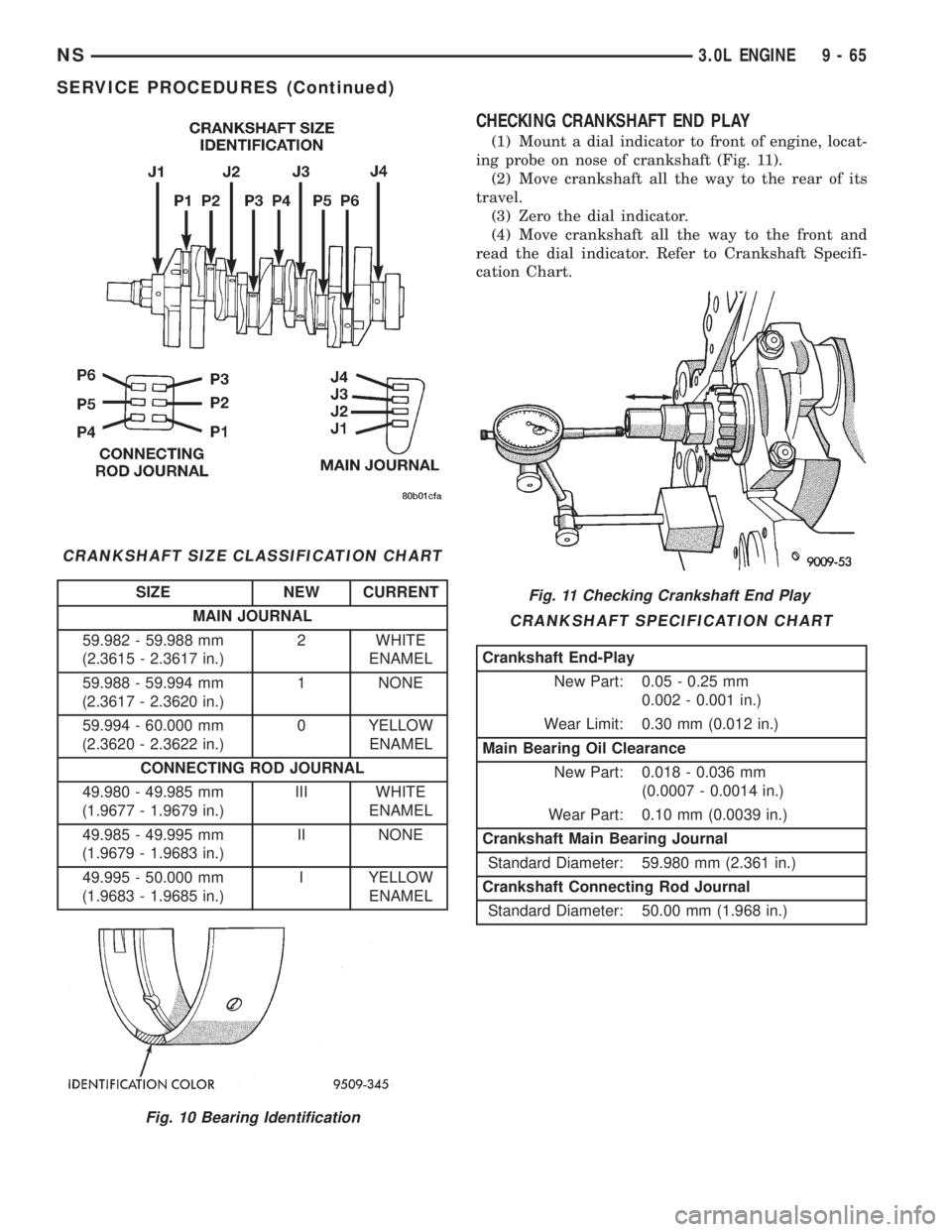
CHECKING CRANKSHAFT END PLAY
(1) Mount a dial indicator to front of engine, locat-
ing probe on nose of crankshaft (Fig. 11).
(2) Move crankshaft all the way to the rear of its
travel.
(3) Zero the dial indicator.
(4) Move crankshaft all the way to the front and
read the dial indicator. Refer to Crankshaft Specifi-
cation Chart.
CRANKSHAFT SIZE CLASSIFICATION CHART
SIZE NEW CURRENT
MAIN JOURNAL
59.982 - 59.988 mm
(2.3615 - 2.3617 in.)2 WHITE
ENAMEL
59.988 - 59.994 mm
(2.3617 - 2.3620 in.)1 NONE
59.994 - 60.000 mm
(2.3620 - 2.3622 in.)0 YELLOW
ENAMEL
CONNECTING ROD JOURNAL
49.980 - 49.985 mm
(1.9677 - 1.9679 in.)III WHITE
ENAMEL
49.985 - 49.995 mm
(1.9679 - 1.9683 in.)II NONE
49.995 - 50.000 mm
(1.9683 - 1.9685 in.)I YELLOW
ENAMEL
Fig. 10 Bearing Identification
Fig. 11 Checking Crankshaft End Play
CRANKSHAFT SPECIFICATION CHART
Crankshaft End-Play
New Part: 0.05 - 0.25 mm
0.002 - 0.001 in.)
Wear Limit: 0.30 mm (0.012 in.)
Main Bearing Oil Clearance
New Part: 0.018 - 0.036 mm
(0.0007 - 0.0014 in.)
Wear Part: 0.10 mm (0.0039 in.)
Crankshaft Main Bearing Journal
Standard Diameter: 59.980 mm (2.361 in.)
Crankshaft Connecting Rod Journal
Standard Diameter: 50.00 mm (1.968 in.)
NS3.0L ENGINE 9 - 65
SERVICE PROCEDURES (Continued)