1996 CHRYSLER VOYAGER height
[x] Cancel search: heightPage 1106 of 1938
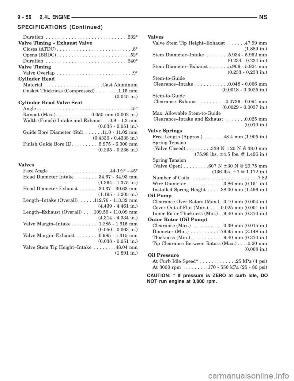
Duration.............................232É
Valve Timing ± Exhaust Valve
Closes (ATDC)...........................8É
Opens (BBDC)..........................52É
Duration.............................240É
Valve Timing
Valve Overlap...........................9É
Cylinder Head
Material.....................Cast Aluminum
Gasket Thickness (Compressed)........1.15 mm
(0.045 in.)
Cylinder Head Valve Seat
Angle.................................45É
Runout (Max.).............0.050 mm (0.002 in.)
Width (Finish) Intake and Exhaust. . .0.9 - 1.3 mm
(0.035 - 0.051 in.)
Guide Bore Diameter (Std).......11.0-11.02 mm
(0.4330 - 0.4338 in.)
Finish Guide Bore ID..........5.975 - 6.000 mm
(0.235 - 0.236 in.)
Valves
Face Angle......................44-1/2É - 45É
Head Diameter Intake.........34.67 - 34.93 mm
(1.364 - 1.375 in.)
Head Diameter Exhaust.......30.37 - 30.63 mm
(1.195 - 1.205 in.)
Length±Intake (Overall)......112.76 - 113.32 mm
(4.439 - 4.461 in.)
Length±Exhaust (Overall). . . .109.59 - 110.09 mm
(4.314 - 4.334 in.)
Valve Margin±Intake..........1.285 - 1.615 mm
(0.050 - 0.063 in.)
Valve Margin±Exhaust........0.985 - 1.315 mm
(0.038 - 0.051 in.)
Valve Stem Tip Height±Intake........48.04 mm
(1.891 in.)Valves
Valve Stem Tip Height±Exhaust.......47.99 mm
(1.889 in.)
Stem Diameter±Intake........5.934 - 5.952 mm
(0.234 - 0.234 in.)
Stem Diameter±Exhaust.......5.906 - 5.924 mm
(0.233 - 0.233 in.)
Stem-to-Guide
Clearance±Intake............0.048 - 0.066 mm
(0.0018 - 0.0025 in.)
Stem-to-Guide
Clearance±Exhaust..........0.0736 - 0.094 mm
(0.0029 - 0.0037 in.)
Max. Allowable Stem-to-Guide
Clearance±Intake and Exhaust.......0.025 mm
(0.010 in.)
Valve Springs
Free Length (Approx.).......48.4 mm (1.905 in.)
Spring Tension
(Valve Closed).........338 N620 N @ 38.0 mm
(75.98 lbs.64.5 lbs. @ 1.496 in.)
Spring Tension
(Valve Open).........607 N630 N @ 29.75 mm
(136 lbs.67 @ 1.172 in.)
Number of Coils........................7.82
Wire Diameter.............3.86 mm (0.151 in.)
Installed Spring Height.....38.00 mm (1.496 in.)
Oil Pump
Clearance Over Rotors (Max.). .0.10 mm (0.004 in.)
Cover Out-of-Flat (Max.).....0.025 mm (0.001 in.)
Inner Rotor Thickness (Min.) . .9.40 mm (0.370 in.)
Outer Rotor (Oil Pump)
Clearance (Max.)...........0.39 mm (0.015 in.)
Diameter (Min.)...........79.95 mm (3.148 in.)
Thickness (Min.)............9.40 mm (0.370 in.)
Tip Clearance Between Rotors (Max.). . . .0.20 mm
(0.008 in.)
Oil Pressure
At Curb Idle Speed*.............25kPa(4psi)
At 3000 rpm.........170 - 550 kPa (25 - 80 psi)
CAUTION: * If pressure is ZERO at curb Idle, DO
NOT run engine at 3,000 rpm.
9 - 56 2.4L ENGINENS
SPECIFICATIONS (Continued)
Page 1112 of 1938
front seal is retained in the oil pump case and the
rear is retained in a block-mounted housing.
PISTONS:Are aluminum alloy with a steel strut,
short height, and thin wall so as to be autothermic
and light weight. The piston head with valve
recesses, in combination with the cylinder head,
forms a compact spherical head with clearance for
total valve lift with pistons at top dead center. The
piston skirt, top and second ring lands are finished to
a tapered roughness for oil retention and high resis-
tance to scuffing. Piston pins, pressed into place, join
the pistons to the connecting rods.
CYLINDER HEAD:The alloy cylinder heads fea-
ture cross-flow type intake and exhaust ports. Valve
guides and inserts are hardened cast iron. Valves of
heat resistance steel are arranged in a V with each
camshaft on center. To improve combustion speed the
chambers are a compact spherical design with a
squish area of approximately 30 percent of the piston
top area. The cylinder heads are common to either
cylinder bank by reversing the direction of installa-
tion.
CAMSHAFTS:Two overhead camshafts provide
valve actuation, one front (radiator side of cylinder
bank) and one rear. The front camshaft is provided
with a distributor drive and is longer. Both cam-
shafts are supported by four bearing journals, thrust
for the front camshaft is taken at journal two and
the rear at journal three. Front and rear camshaft
driving sprockets are interchangeable. The sprockets
and the engine water pump are driven by a single
notched timing belt.
ROCKER ARM SHAFTS:The shafts are retained
by the camshaft bearing journal caps. Four shafts are
used, one for each intake and exhaust rocker arm
assembly on each cylinder head. The hollow shafts
provide a duct for lubricating oil flow from the cylin-
der head to the valve mechanisms.
ROCKER ARMS:Are of light weight die-cast with
roller type follower operating against the cam shaft.
The valve actuating end of the rocker arms are
machined to retain hydraulic lash adjusters, elimi-
nating valve lash adjustment.
VALVES:Are made of heat resistant steel, valve
springs are especially designed to be short. The valve
spring wire cross-section is oval shaped and provides
the same spring tension as longer springs. Valve
spring retainers, locks and seals are conventional.
INTAKE MANIFOLD:The aluminum alloy mani-
fold is a cross type with long runners to improve
inertia. The runners, attaching below at the cylinder
head, also attach above and support an air plenum.
The air plenum chamber absorbs air pulsations cre-
ated during the suction phase of each cylinder.
EXHAUST MANIFOLDS:Both manifolds are a
log style made of ductile cast iron. Exhaust gasses,collected from the front cylinder bank, leave the front
manifold through an end outlet and are fed through
an upper crossover tube to the rear manifold. The
collected exhaust from both manifolds are combined,
and exit to the exhaust pipe through an articulated
joint.
DIAGNOSIS AND TESTING
CHECKING ENGINE OIL PRESSURE
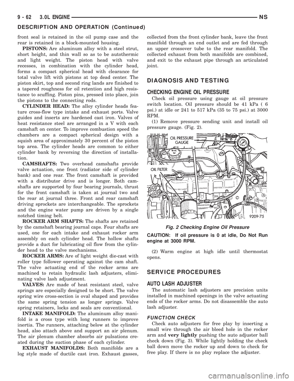
Check oil pressure using gauge at oil pressure
switch location. Oil pressure should be 41 kPa ( 6
psi.) at idle or 241 to 517 kPa (35 to 75 psi.) at 3000
RPM.
(1) Remove pressure sending unit and install oil
pressure gauge. (Fig. 2).
CAUTION: If oil pressure is 0 at idle, Do Not Run
engine at 3000 RPM.
(2) Warm engine at high idle until thermostat
opens.
SERVICE PROCEDURES
AUTO LASH ADJUSTER
The automatic lash adjusters are precision units
installed in machined openings in the valve actuating
ends of the rocker arms. Do not disassemble the auto
lash adjuster.
FUNCTION CHECK
Check auto adjusters for free play by inserting a
small wire through the air bleed hole in the rocker
arm andvery lightlypushing the auto adjuster ball
check down (Fig. 3). While lightly holding the check
ball down move the rocker up and down to check for
free play. If there is no play replace the adjuster.
Fig. 2 Checking Engine Oil Pressure
9 - 62 3.0L ENGINENS
DESCRIPTION AND OPERATION (Continued)
Page 1116 of 1938
VALVE SERVICE RECONDITION
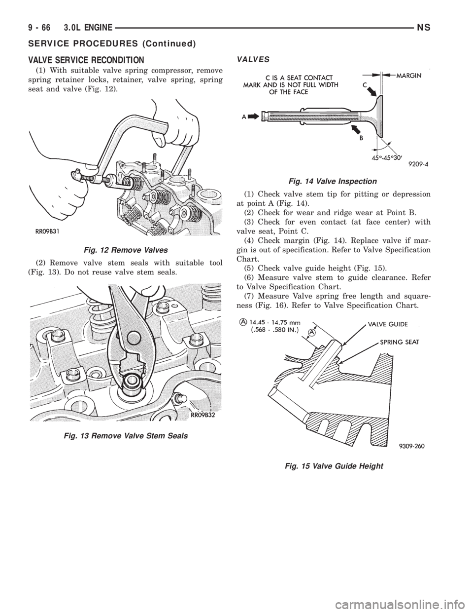
(1) With suitable valve spring compressor, remove
spring retainer locks, retainer, valve spring, spring
seat and valve (Fig. 12).
(2) Remove valve stem seals with suitable tool
(Fig. 13). Do not reuse valve stem seals.
VALVES
(1) Check valve stem tip for pitting or depression
at point A (Fig. 14).
(2) Check for wear and ridge wear at Point B.
(3) Check for even contact (at face center) with
valve seat, Point C.
(4) Check margin (Fig. 14). Replace valve if mar-
gin is out of specification. Refer to Valve Specification
Chart.
(5) Check valve guide height (Fig. 15).
(6) Measure valve stem to guide clearance. Refer
to Valve Specification Chart.
(7) Measure Valve spring free length and square-
ness (Fig. 16). Refer to Valve Specification Chart.
Fig. 12 Remove Valves
Fig. 13 Remove Valve Stem Seals
Fig. 14 Valve Inspection
Fig. 15 Valve Guide Height
9 - 66 3.0L ENGINENS
SERVICE PROCEDURES (Continued)
Page 1121 of 1938
(6) When removing right cylinder head cover, dis-
connect generator wiring and remove generator.
(7) Relocate spark plug wires.
(8) Remove vacuum connections.
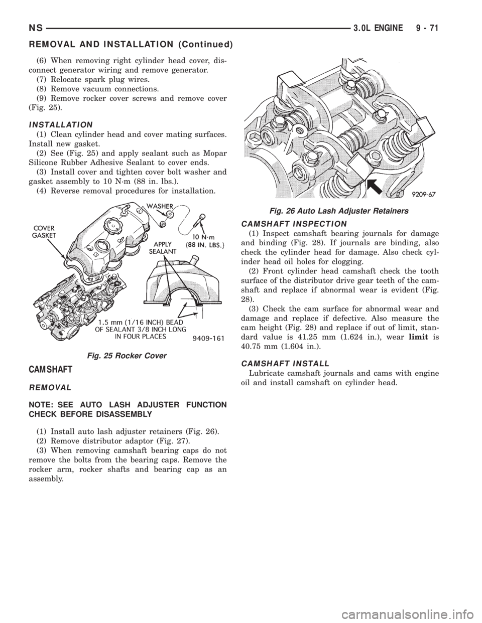
(9) Remove rocker cover screws and remove cover
(Fig. 25).
INSTALLATION
(1) Clean cylinder head and cover mating surfaces.
Install new gasket.
(2) See (Fig. 25) and apply sealant such as Mopar
Silicone Rubber Adhesive Sealant to cover ends.
(3) Install cover and tighten cover bolt washer and
gasket assembly to 10 N´m (88 in. lbs.).
(4) Reverse removal procedures for installation.
CAMSHAFT
REMOVAL
NOTE: SEE AUTO LASH ADJUSTER FUNCTION
CHECK BEFORE DISASSEMBLY
(1) Install auto lash adjuster retainers (Fig. 26).
(2) Remove distributor adaptor (Fig. 27).
(3) When removing camshaft bearing caps do not
remove the bolts from the bearing caps. Remove the
rocker arm, rocker shafts and bearing cap as an
assembly.
CAMSHAFT INSPECTION
(1) Inspect camshaft bearing journals for damage
and binding (Fig. 28). If journals are binding, also
check the cylinder head for damage. Also check cyl-
inder head oil holes for clogging.
(2) Front cylinder head camshaft check the tooth
surface of the distributor drive gear teeth of the cam-
shaft and replace if abnormal wear is evident (Fig.
28).
(3) Check the cam surface for abnormal wear and
damage and replace if defective. Also measure the
cam height (Fig. 28) and replace if out of limit, stan-
dard value is 41.25 mm (1.624 in.), wearlimitis
40.75 mm (1.604 in.).
CAMSHAFT INSTALL
Lubricate camshaft journals and cams with engine
oil and install camshaft on cylinder head.
Fig. 25 Rocker Cover
Fig. 26 Auto Lash Adjuster Retainers
NS3.0L ENGINE 9 - 71
REMOVAL AND INSTALLATION (Continued)
Page 1139 of 1938
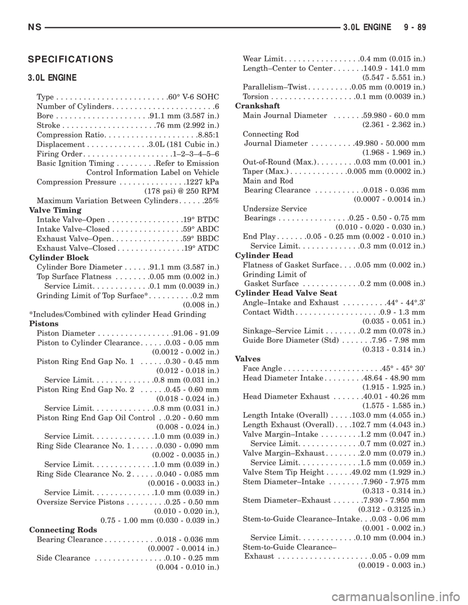
SPECIFICATIONS
3.0L ENGINE
Type.........................60É V-6 SOHC
Number of Cylinders.......................6
Bore.....................91.1 mm (3.587 in.)
Stroke.....................76mm(2.992 in.)
Compression Ratio.....................8.85:1
Displacement..............3.0L (181 Cubic in.)
Firing Order....................1±2±3±4±5±6
Basic Ignition Timing.........Refer to Emission
Control Information Label on Vehicle
Compression Pressure...............1227 kPa
(178 psi) @ 250 RPM
Maximum Variation Between Cylinders......25%
Valve Timing
Intake Valve±Open.................19É BTDC
Intake Valve±Closed................59É ABDC
Exhaust Valve±Open................59É BBDC
Exhaust Valve±Closed...............19É ATDC
Cylinder Block
Cylinder Bore Diameter......91.1 mm (3.587 in.)
Top Surface Flatness........0.05 mm (0.002 in.)
Service Limit.............0.1 mm (0.0039 in.)
Grinding Limit of Top Surface*..........0.2 mm
(0.008 in.)
*Includes/Combined with cylinder Head Grinding
Pistons
Piston Diameter.................91.06 - 91.09
Piston to Cylinder Clearance......0.03 - 0.05 mm
(0.0012 - 0.002 in.)
Piston Ring End Gap No. 1......0.30 - 0.45 mm
(0.012 - 0.018 in.)
Service Limit..............0.8 mm (0.031 in.)
Piston Ring End Gap No. 2......0.45 - 0.60 mm
(0.018 - 0.024 in.)
Service Limit..............0.8 mm (0.031 in.)
Piston Ring End Gap Oil Control . .0.20 - 0.60 mm
(0.008 - 0.024 in.)
Service Limit..............1.0 mm (0.039 in.)
Ring Side Clearance No. 1......0.030 - 0.090 mm
(0.002 - 0.0035 in.)
Service Limit..............1.0 mm (0.039 in.)
Ring Side Clearance No. 2......0.040 - 0.085 mm
(0.0016 - 0.0033 in.)
Service Limit..............1.0 mm (0.039 in.)
Oversize Service Pistons.........0.25 - 0.50 mm
(0.010 - 0.020 in.),
0.75 - 1.00 mm (0.030 - 0.039 in.)
Connecting Rods
Bearing Clearance............0.018 - 0.036 mm
(0.0007 - 0.0014 in.)
Side Clearance................0.10 - 0.25 mm
(0.004 - 0.010 in.)Wear Limit.................0.4 mm (0.015 in.)
Length±Center to Center.......140.9 - 141.0 mm
(5.547 - 5.551 in.)
Parallelism±Twist..........0.05 mm (0.0019 in.)
Torsion...................0.1 mm (0.0039 in.)
Crankshaft
Main Journal Diameter.......59.980 - 60.0 mm
(2.361 - 2.362 in.)
Connecting Rod
Journal Diameter..........49.980 - 50.000 mm
(1.968 - 1.969 in.)
Out-of-Round (Max.).........0.03 mm (0.001 in.)
Taper (Max.).............0.005 mm (0.0002 in.)
Main and Rod
Bearing Clearance...........0.018 - 0.036 mm
(0.0007 - 0.0014 in.)
Undersize Service
Bearings................0.25 - 0.50 - 0.75 mm
(0.010 - 0.020 - 0.030 in.)
End Play.......0.05 - 0.25 mm (0.002 - 0.010 in.)
Service Limit..............0.3 mm (0.012 in.)
Cylinder Head
Flatness of Gasket Surface. . . .0.05 mm (0.002 in.)
Grinding Limit of
Gasket Surface.............0.2 mm (0.008 in.)
Cylinder Head Valve Seat
Angle±Intake and Exhaust..........44É - 44É.3'
Contact Width...................0.9 - 1.3 mm
(0.035 - 0.051 in.)
Sinkage±Service Limit........0.2 mm (0.078 in.)
Guide Bore Diameter (Std).......7.95 - 7.98 mm
(0.313 - 0.314 in.)
Valves
Face Angle......................45É - 45É 30'
Head Diameter Intake.........48.64 - 48.90 mm
(1.915 - 1.925 in.)
Head Diameter Exhaust.......40.01 - 40.26 mm
(1.575 - 1.585 in.)
Length Intake (Overall).....103.0 mm (4.055 in.)
Length Exhaust (Overall). . . .102.7 mm (4.043 in.)
Valve Margin±Intake.........1.2 mm (0.047 in.)
Service Limit..............0.7 mm (0.027 in.)
Valve Margin±Exhaust........2.0 mm (0.079 in.)
Service Limit..............1.5 mm (0.059 in.)
Valve Stem Tip Height......49.02 mm (1.929 in.)
Stem Diameter±Intake........7.960 - 7.975 mm
(0.313 - 0.314 in.)
Stem Diameter±Exhaust.......7.930 - 7.950 mm
(0.312 - 0.3125 in.)
Stem-to-Guide Clearance±Intake . . .0.03 - 0.06 mm
(0.001 - 0.002 in.)
Service Limit.............0.10 mm (0.004 in.)
Stem-to-Guide Clearance±
Exhaust.....................0.05 - 0.09 mm
(0.0019 - 0.003 in.)
NS3.0L ENGINE 9 - 89
Page 1140 of 1938
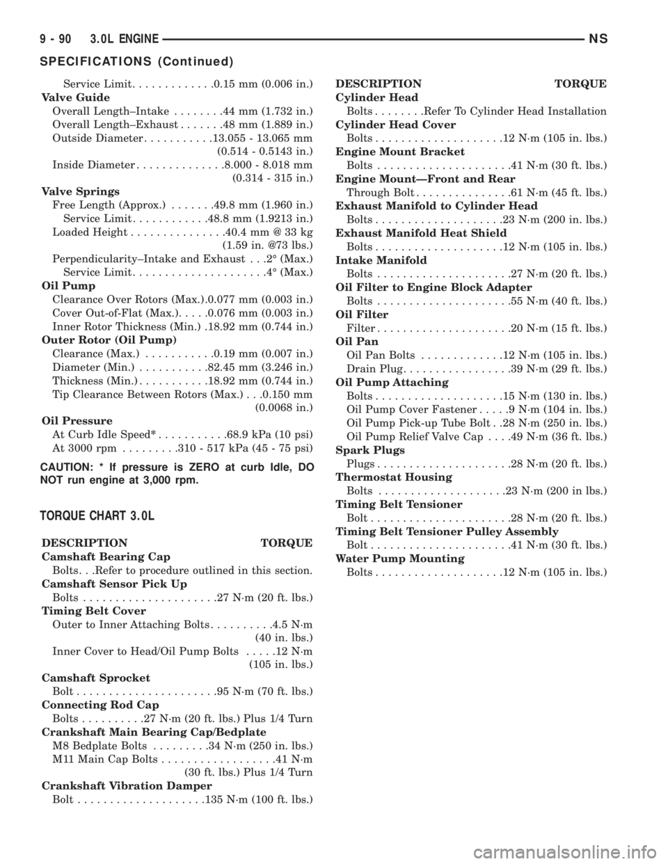
Service Limit.............0.15 mm (0.006 in.)
Valve Guide
Overall Length±Intake........44mm(1.732 in.)
Overall Length±Exhaust.......48mm(1.889 in.)
Outside Diameter...........13.055 - 13.065 mm
(0.514 - 0.5143 in.)
Inside Diameter..............8.000 - 8.018 mm
(0.314 - 315 in.)
Valve Springs
Free Length (Approx.).......49.8 mm (1.960 in.)
Service Limit............48.8 mm (1.9213 in.)
Loaded Height...............40.4 mm @ 33 kg
(1.59 in. @73 lbs.)
Perpendicularity±Intake and Exhaust . . .2É (Max.)
Service Limit.....................4É(Max.)
Oil Pump
Clearance Over Rotors (Max.) .0.077 mm (0.003 in.)
Cover Out-of-Flat (Max.).....0.076 mm (0.003 in.)
Inner Rotor Thickness (Min.) .18.92 mm (0.744 in.)
Outer Rotor (Oil Pump)
Clearance (Max.)...........0.19 mm (0.007 in.)
Diameter (Min.)...........82.45 mm (3.246 in.)
Thickness (Min.)...........18.92 mm (0.744 in.)
Tip Clearance Between Rotors (Max.) . . .0.150 mm
(0.0068 in.)
Oil Pressure
At Curb Idle Speed*...........68.9 kPa (10 psi)
At 3000 rpm.........310 - 517 kPa (45 - 75 psi)
CAUTION: * If pressure is ZERO at curb Idle, DO
NOT run engine at 3,000 rpm.
TORQUE CHART 3.0L
DESCRIPTION TORQUE
Camshaft Bearing Cap
Bolts. . .Refer to procedure outlined in this section.
Camshaft Sensor Pick Up
Bolts.....................27N´m(20ft.lbs.)
Timing Belt Cover
Outer to Inner Attaching Bolts..........4.5 N´m
(40 in. lbs.)
Inner Cover to Head/Oil Pump Bolts.....12N´m
(105 in. lbs.)
Camshaft Sprocket
Bolt......................95N´m(70ft.lbs.)
Connecting Rod Cap
Bolts..........27N´m(20ft.lbs.) Plus 1/4 Turn
Crankshaft Main Bearing Cap/Bedplate
M8 Bedplate Bolts.........34N´m(250 in. lbs.)
M11 Main Cap Bolts..................41N´m
(30 ft. lbs.) Plus 1/4 Turn
Crankshaft Vibration Damper
Bolt....................135 N´m (100 ft. lbs.)DESCRIPTION TORQUE
Cylinder Head
Bolts........Refer To Cylinder Head Installation
Cylinder Head Cover
Bolts....................12N´m(105 in. lbs.)
Engine Mount Bracket
Bolts.....................41N´m(30ft.lbs.)
Engine MountÐFront and Rear
Through Bolt...............61N´m(45ft.lbs.)
Exhaust Manifold to Cylinder Head
Bolts....................23N´m(200 in. lbs.)
Exhaust Manifold Heat Shield
Bolts....................12N´m(105 in. lbs.)
Intake Manifold
Bolts.....................27N´m(20ft.lbs.)
Oil Filter to Engine Block Adapter
Bolts.....................55N´m(40ft.lbs.)
Oil Filter
Filter.....................20N´m(15ft.lbs.)
Oil Pan
Oil Pan Bolts.............12N´m(105 in. lbs.)
Drain Plug.................39N´m(29ft.lbs.)
Oil Pump Attaching
Bolts....................15N´m(130 in. lbs.)
Oil Pump Cover Fastener.....9N´m(104 in. lbs.)
Oil Pump Pick-up Tube Bolt . .28 N´m (250 in. lbs.)
Oil Pump Relief Valve Cap. . . .49 N´m (36 ft. lbs.)
Spark Plugs
Plugs.....................28N´m(20ft.lbs.)
Thermostat Housing
Bolts....................23N´m(200 in lbs.)
Timing Belt Tensioner
Bolt......................28N´m(20ft.lbs.)
Timing Belt Tensioner Pulley Assembly
Bolt......................41N´m(30ft.lbs.)
Water Pump Mounting
Bolts....................12N´m(105 in. lbs.)
9 - 90 3.0L ENGINENS
SPECIFICATIONS (Continued)
Page 1152 of 1938
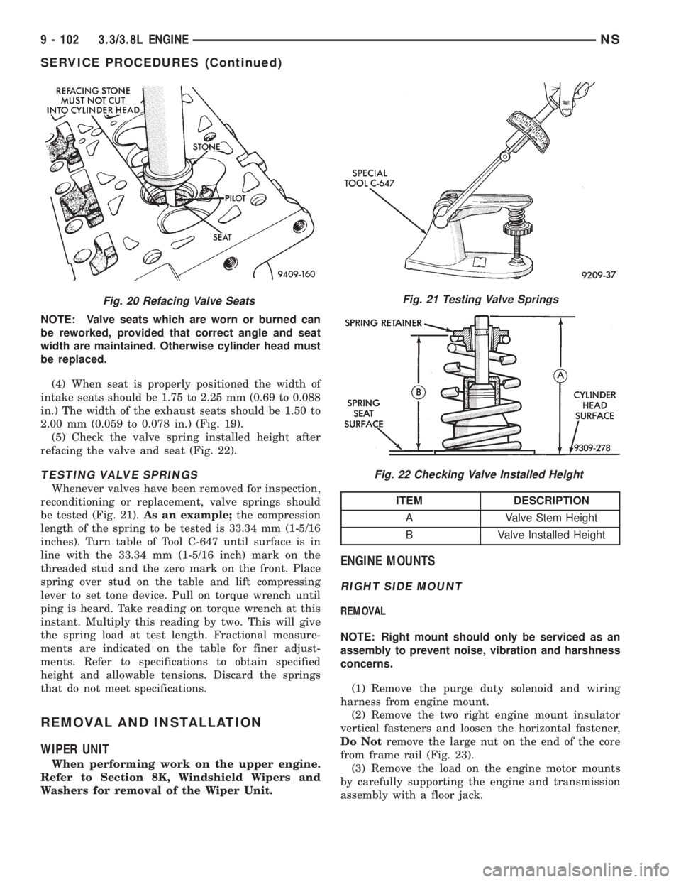
NOTE: Valve seats which are worn or burned can
be reworked, provided that correct angle and seat
width are maintained. Otherwise cylinder head must
be replaced.
(4) When seat is properly positioned the width of
intake seats should be 1.75 to 2.25 mm (0.69 to 0.088
in.) The width of the exhaust seats should be 1.50 to
2.00 mm (0.059 to 0.078 in.) (Fig. 19).
(5) Check the valve spring installed height after
refacing the valve and seat (Fig. 22).
TESTING VALVE SPRINGS
Whenever valves have been removed for inspection,
reconditioning or replacement, valve springs should
be tested (Fig. 21).As an example;the compression
length of the spring to be tested is 33.34 mm (1-5/16
inches). Turn table of Tool C-647 until surface is in
line with the 33.34 mm (1-5/16 inch) mark on the
threaded stud and the zero mark on the front. Place
spring over stud on the table and lift compressing
lever to set tone device. Pull on torque wrench until
ping is heard. Take reading on torque wrench at this
instant. Multiply this reading by two. This will give
the spring load at test length. Fractional measure-
ments are indicated on the table for finer adjust-
ments. Refer to specifications to obtain specified
height and allowable tensions. Discard the springs
that do not meet specifications.
REMOVAL AND INSTALLATION
WIPER UNIT
When performing work on the upper engine.
Refer to Section 8K, Windshield Wipers and
Washers for removal of the Wiper Unit.
ENGINE MOUNTS
RIGHT SIDE MOUNT
REMOVAL
NOTE: Right mount should only be serviced as an
assembly to prevent noise, vibration and harshness
concerns.
(1) Remove the purge duty solenoid and wiring
harness from engine mount.
(2) Remove the two right engine mount insulator
vertical fasteners and loosen the horizontal fastener,
Do Notremove the large nut on the end of the core
from frame rail (Fig. 23).
(3) Remove the load on the engine motor mounts
by carefully supporting the engine and transmission
assembly with a floor jack.
Fig. 20 Refacing Valve SeatsFig. 21 Testing Valve Springs
Fig. 22 Checking Valve Installed Height
ITEM DESCRIPTION
A Valve Stem Height
B Valve Installed Height
9 - 102 3.3/3.8L ENGINENS
SERVICE PROCEDURES (Continued)
Page 1160 of 1938
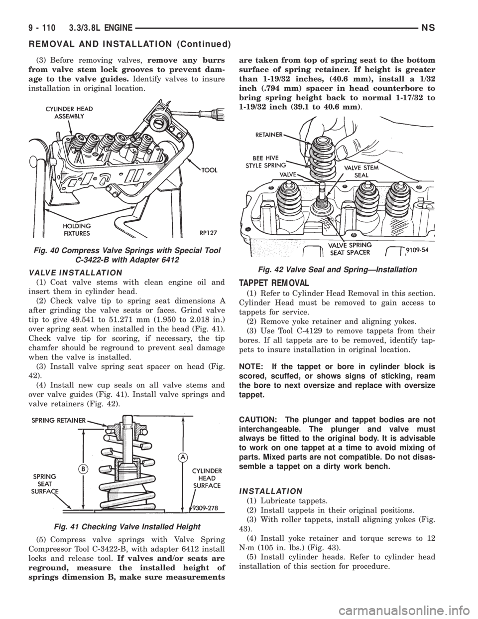
(3) Before removing valves,remove any burrs
from valve stem lock grooves to prevent dam-
age to the valve guides.Identify valves to insure
installation in original location.
VALVE INSTALLATION
(1) Coat valve stems with clean engine oil and
insert them in cylinder head.
(2) Check valve tip to spring seat dimensions A
after grinding the valve seats or faces. Grind valve
tip to give 49.541 to 51.271 mm (1.950 to 2.018 in.)
over spring seat when installed in the head (Fig. 41).
Check valve tip for scoring, if necessary, the tip
chamfer should be reground to prevent seal damage
when the valve is installed.
(3) Install valve spring seat spacer on head (Fig.
42).
(4) Install new cup seals on all valve stems and
over valve guides (Fig. 41). Install valve springs and
valve retainers (Fig. 42).
(5) Compress valve springs with Valve Spring
Compressor Tool C-3422-B, with adapter 6412 install
locks and release tool.If valves and/or seats are
reground, measure the installed height of
springs dimension B, make sure measurementsare taken from top of spring seat to the bottom
surface of spring retainer. If height is greater
than 1-19/32 inches, (40.6 mm), install a 1/32
inch (.794 mm) spacer in head counterbore to
bring spring height back to normal 1-17/32 to
1-19/32 inch (39.1 to 40.6 mm).TAPPET REMOVAL
(1) Refer to Cylinder Head Removal in this section.
Cylinder Head must be removed to gain access to
tappets for service.
(2) Remove yoke retainer and aligning yokes.
(3) Use Tool C-4129 to remove tappets from their
bores. If all tappets are to be removed, identify tap-
pets to insure installation in original location.
NOTE: If the tappet or bore in cylinder block is
scored, scuffed, or shows signs of sticking, ream
the bore to next oversize and replace with oversize
tappet.
CAUTION: The plunger and tappet bodies are not
interchangeable. The plunger and valve must
always be fitted to the original body. It is advisable
to work on one tappet at a time to avoid mixing of
parts. Mixed parts are not compatible. Do not disas-
semble a tappet on a dirty work bench.
INSTALLATION
(1) Lubricate tappets.
(2) Install tappets in their original positions.
(3) With roller tappets, install aligning yokes (Fig.
43).
(4) Install yoke retainer and torque screws to 12
N´m (105 in. lbs.) (Fig. 43).
(5) Install cylinder heads. Refer to cylinder head
installation of this section for procedure.
Fig. 40 Compress Valve Springs with Special Tool
C-3422-B with Adapter 6412
Fig. 41 Checking Valve Installed Height
Fig. 42 Valve Seal and SpringÐInstallation
9 - 110 3.3/3.8L ENGINENS
REMOVAL AND INSTALLATION (Continued)