1996 CHRYSLER VOYAGER height
[x] Cancel search: heightPage 483 of 1938

HEADLAMP ALIGNMENT
INDEX
page page
SERVICE PROCEDURES
HEADLAMP ALIGNMENT PREPARATION...... 5ADJUSTMENTS
HEADLAMP/FOG LAMP ADJUSTMENT USING
ALIGNMENT SCREEN.................. 5
SERVICE PROCEDURES
HEADLAMP ALIGNMENT PREPARATION
(1) Verify headlamp dimmer switch and high beam
indicator operation.
(2) Verify that the headlamp leveling switch is in
the ª0º position.
(3) Inspect and correct damaged or defective com-
ponents that could interfere with proper headlamp
alignment.
(4) Verify proper tire inflation.
(5) Clean headlamp lenses.
(6) Verify that luggage area is loaded as the vehi-
cle is routinely used.
(7) Fuel tank should be FULL. Add 2.94 kg (6.5
lbs.) of weight over the fuel tank for each estimated
gallon of missing fuel.
ADJUSTMENTS
HEADLAMP/FOG LAMP ADJUSTMENT USING
ALIGNMENT SCREEN
ALIGNMENT SCREEN PREPARATION
(1) Position vehicle on a level surface perpendicu-
lar to a flat wall 10 meters (32.8 ft.) away from front
of headlamp lens (Fig. 1).
(2) Place 75 kg in the driver's seat to simulate the
ride height of the vehicle when driven.
(3) If necessary, tape a line on the floor 10 meters
(32.8 ft) away from and parallel to the wall.
(4) From the floor up 1.27 meters (5 ft), tape a line
on the wall at the centerline of the vehicle. Sight
along the centerline of the vehicle (from rear of vehi-
cle forward) to verify accuracy of the line placement.
NS/GSLAMPS 8L - 5
Page 1065 of 1938
BALANCE SHAFTS
Balance shaft lubrication is provided through an
oil passage from the number 1 main bearing cap
through the balance shaft carrier support leg. This
passage directly supplies oil to the front bearings and
internal machined passages in the shafts that routes
oil from front to rear shaft bearing journals
SPLASH LUBRICATION
Oil returning to the pan from pressurized compo-
nents supplies lubrication to the valve stems. Cylin-
der bores and wrist pins are splash lubricated from
directed slots on the connecting rod thrust collars.
ENGINE COMPONENTS
BALANCE SHAFTS:2.4L engines are equipped
with two balance shafts installed in a carrier
attached to the lower crankcase. The shafts intercon-
nect through gears to rotate in opposite directions.These gears are driven by a short chain from the
crankshaft, to rotate at two times crankshaft speed.
This counterbalances certain engine reciprocating
masses.
CYLINDER BLOCK AND BEDPLATE ASSEM-
B LY:A closed deck design is used for cooling and
weight reduction with water pump molded into the
block. Nominal wall thickness is 4.5 mm. The bed-
plate incorporates main bearing caps. Rear seal
retainer is integral with the block.
CRANKSHAFT:A nodular cast iron crankshaft is
used. The engine has 5 main bearings, with number
3 flanged to control thrust. The 60 mm diameter
main and 50 mm diameter crank pin journals (all)
have undercut fillets that are deep rolled for added
strength. To evenly distribute bearing loads and min-
imize internal stress, 8 counterweights are used.
Hydrodynamic seals provide end sealing, where the
crankshaft exits the block. Anaerobic gasket material
is used for parting line sealing in the block. A sin-
tered powder metal timing belt sprocket is mounted
on the crankshaft nose. This sprocket provides
motive power; via timing belt to the camshaft sprock-
ets (providing timed valve actuation) and to the
water pump.
PISTONS:There is provisions for free wheeling
valve train. Piston has a unique height. All engines
use pressed in piston pins to attach forged powder
metal connecting rods. Incorporate hex head cap
screw threaded into the connecting rod. Piston and
Rods are serviced as a assembly.
PISTONS RINGS:The piston rings include a
molybdenum faced top ring for reliable compression
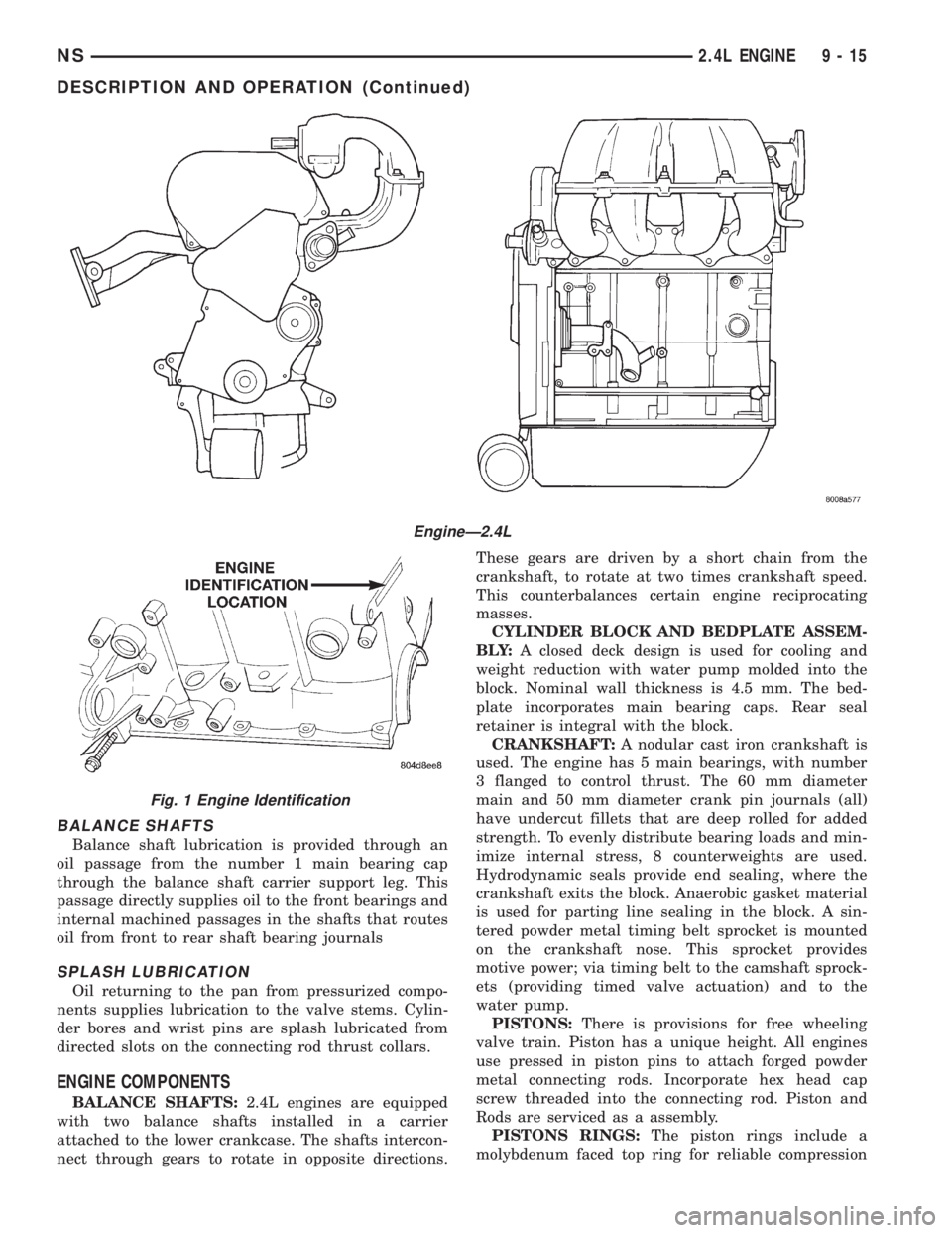
EngineÐ2.4L
Fig. 1 Engine Identification
NS2.4L ENGINE 9 - 15
DESCRIPTION AND OPERATION (Continued)
Page 1071 of 1938
OPTIONAL CRANKSHAFT END PLAY CHECK
(1) Move crankshaft all the way to the rear of its
travel using a lever inserted between a main bearing
cap and a crankshaft cheek, using care not to dam-
age any bearing surface.DO NOTloosen main bear-
ing cap.
(2) Use a feeler gauge between number three
thrust bearing and machined crankshaft surface to
determine end play.
VALVE SERVICE RECONDITION
VALVE REMOVAL
(1) With cylinder head removed, compress valve
springs using Special Tool C-3422-B or equivalent.
(2) Remove valve retaining locks, valve spring
retainers, valve stem seals and valve springs.
(3) Before removing valves,remove any burrs
from valve stem lock grooves to prevent dam-
age to the valve guides.Identify valves to insure
installation in original location.
VALVE INSPECTION
(1) Clean valves thoroughly and discard burned,
warped and cracked valves.
(2) Measure valve stems for wear. Measure stem
about 60 mm beneath the valve lock grooves.
(3) If valve stems are worn more than 0.05 mm
(0.002 in.), replace valve.
VALVE GUIDES
(1) Remove carbon and varnish deposits from
inside of valve guides with a reliable guide cleaner.
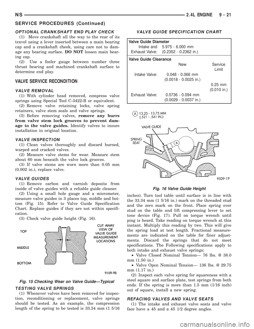
(2) Using a small hole gauge and a micrometer,
measure valve guides in 3 places top, middle and bot-
tom (Fig. 15). Refer to Valve Guide Specification
Chart. Replace guides if they are not within specifi-
cation.
(3) Check valve guide height (Fig. 16).
TESTING VALVE SPRINGS
(1) Whenever valves have been removed for inspec-
tion, reconditioning or replacement, valve springs
should be tested. As an example, the compression
length of the spring to be tested is 33.34 mm (1 5/16inches). Turn tool table until surface is in line with
the 33.34 mm (1 5/16 in.) mark on the threaded stud
and the zero mark on the front. Place spring over
stud on the table and lift compressing lever to set
tone device (Fig. 17). Pull on torque wrench until
ping is heard. Take reading on torque wrench at this
instant. Multiply this reading by two. This will give
the spring load at test length. Fractional measure-
ments are indicated on the table for finer adjust-
ments. Discard the springs that do not meet
specifications. The Following specifications apply to
both intake and exhaust valve springs;
²Valve Closed Nominal TensionÐ 76 lbs. @ 38.0
mm (1.50 in.)
²Valve Open Nominal TensionÐ 136 lbs. @ 29.75
mm (1.17 in.)
(2) Inspect each valve spring for squareness with a
steel square and surface plate, test springs from both
ends. If the spring is more than 1.5 mm (1/16 inch)
out of square, install a new spring.
REFACING VALVES AND VALVE SEATS
(1) The intake and exhaust valve seats and valve
face have a 45 and a 45 1/2 degree angles.
Fig. 15 Checking Wear on Valve GuideÐTypical
VALVE GUIDE SPECIFICATION CHART
Valve Guide Diameter
Intake and
Exhaust Valve:5.975 - 6.000 mm
(0.2352 - 0.2362 in.)
Valve Guide Clearance
New Service
Limit
Intake Valve: 0.048 - 0.066 mm
(0.0018 - 0.0025 in.)
0.25 mm
(0.010 in.)
Exhaust Valve: 0.0736 - 0.094 mm
(0.0029 - 0.0037 in.)
Fig. 16 Valve Guide Height
NS2.4L ENGINE 9 - 21
SERVICE PROCEDURES (Continued)
Page 1072 of 1938
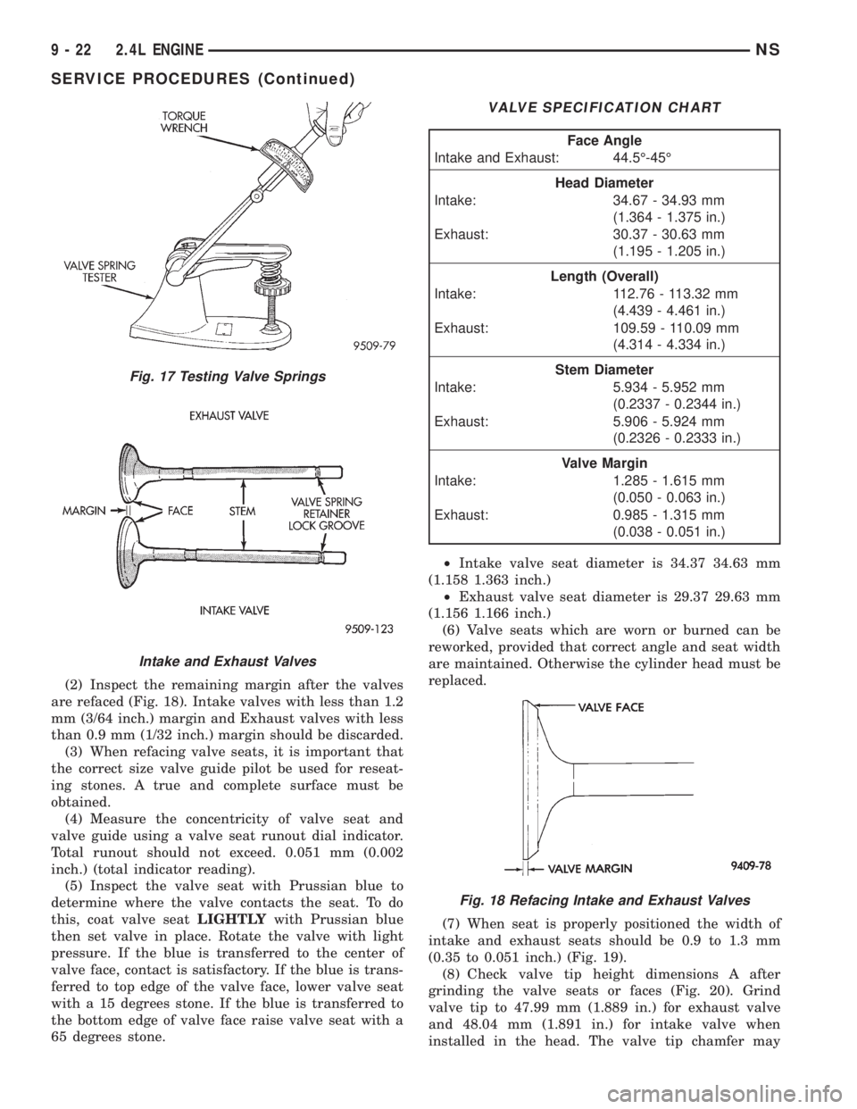
(2) Inspect the remaining margin after the valves
are refaced (Fig. 18). Intake valves with less than 1.2
mm (3/64 inch.) margin and Exhaust valves with less
than 0.9 mm (1/32 inch.) margin should be discarded.
(3) When refacing valve seats, it is important that
the correct size valve guide pilot be used for reseat-
ing stones. A true and complete surface must be
obtained.
(4) Measure the concentricity of valve seat and
valve guide using a valve seat runout dial indicator.
Total runout should not exceed. 0.051 mm (0.002
inch.) (total indicator reading).
(5) Inspect the valve seat with Prussian blue to
determine where the valve contacts the seat. To do
this, coat valve seatLIGHTLYwith Prussian blue
then set valve in place. Rotate the valve with light
pressure. If the blue is transferred to the center of
valve face, contact is satisfactory. If the blue is trans-
ferred to top edge of the valve face, lower valve seat
with a 15 degrees stone. If the blue is transferred to
the bottom edge of valve face raise valve seat with a
65 degrees stone.²Intake valve seat diameter is 34.37 34.63 mm
(1.158 1.363 inch.)
²Exhaust valve seat diameter is 29.37 29.63 mm
(1.156 1.166 inch.)
(6) Valve seats which are worn or burned can be
reworked, provided that correct angle and seat width
are maintained. Otherwise the cylinder head must be
replaced.
(7) When seat is properly positioned the width of
intake and exhaust seats should be 0.9 to 1.3 mm
(0.35 to 0.051 inch.) (Fig. 19).
(8) Check valve tip height dimensions A after
grinding the valve seats or faces (Fig. 20). Grind
valve tip to 47.99 mm (1.889 in.) for exhaust valve
and 48.04 mm (1.891 in.) for intake valve when
installed in the head. The valve tip chamfer may
Fig. 17 Testing Valve Springs
Intake and Exhaust Valves
VALVE SPECIFICATION CHART
Face Angle
Intake and Exhaust: 44.5É-45É
Head Diameter
Intake: 34.67 - 34.93 mm
(1.364 - 1.375 in.)
Exhaust: 30.37 - 30.63 mm
(1.195 - 1.205 in.)
Length (Overall)
Intake: 112.76 - 113.32 mm
(4.439 - 4.461 in.)
Exhaust: 109.59 - 110.09 mm
(4.314 - 4.334 in.)
Stem Diameter
Intake: 5.934 - 5.952 mm
(0.2337 - 0.2344 in.)
Exhaust: 5.906 - 5.924 mm
(0.2326 - 0.2333 in.)
Valve Margin
Intake: 1.285 - 1.615 mm
(0.050 - 0.063 in.)
Exhaust: 0.985 - 1.315 mm
(0.038 - 0.051 in.)
Fig. 18 Refacing Intake and Exhaust Valves
9 - 22 2.4L ENGINENS
SERVICE PROCEDURES (Continued)
Page 1073 of 1938
need to be reground to prevent seal damage when
the valve is installed.
VALVE INSTALLATION
(1) Coat valve stems with clean engine oil and
insert in cylinder head.
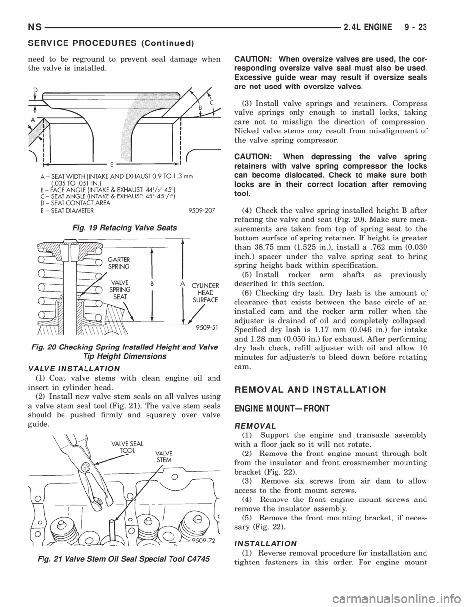
(2) Install new valve stem seals on all valves using
a valve stem seal tool (Fig. 21). The valve stem seals
should be pushed firmly and squarely over valve
guide.CAUTION: When oversize valves are used, the cor-
responding oversize valve seal must also be used.
Excessive guide wear may result if oversize seals
are not used with oversize valves.
(3) Install valve springs and retainers. Compress
valve springs only enough to install locks, taking
care not to misalign the direction of compression.
Nicked valve stems may result from misalignment of
the valve spring compressor.
CAUTION: When depressing the valve spring
retainers with valve spring compressor the locks
can become dislocated. Check to make sure both
locks are in their correct location after removing
tool.
(4) Check the valve spring installed height B after
refacing the valve and seat (Fig. 20). Make sure mea-
surements are taken from top of spring seat to the
bottom surface of spring retainer. If height is greater
than 38.75 mm (1.525 in.), install a .762 mm (0.030
inch.) spacer under the valve spring seat to bring
spring height back within specification.
(5) Install rocker arm shafts as previously
described in this section.
(6) Checking dry lash. Dry lash is the amount of
clearance that exists between the base circle of an
installed cam and the rocker arm roller when the
adjuster is drained of oil and completely collapsed.
Specified dry lash is 1.17 mm (0.046 in.) for intake
and 1.28 mm (0.050 in.) for exhaust. After performing
dry lash check, refill adjuster with oil and allow 10
minutes for adjuster/s to bleed down before rotating
cam.
REMOVAL AND INSTALLATION
ENGINE MOUNTÐFRONT
REMOVAL
(1) Support the engine and transaxle assembly
with a floor jack so it will not rotate.
(2) Remove the front engine mount through bolt
from the insulator and front crossmember mounting
bracket (Fig. 22).
(3) Remove six screws from air dam to allow
access to the front mount screws.
(4) Remove the front engine mount screws and
remove the insulator assembly.
(5) Remove the front mounting bracket, if neces-
sary (Fig. 22).
INSTALLATION
(1) Reverse removal procedure for installation and
tighten fasteners in this order. For engine mount
Fig. 19 Refacing Valve Seats
Fig. 20 Checking Spring Installed Height and Valve
Tip Height Dimensions
Fig. 21 Valve Stem Oil Seal Special Tool C4745
NS2.4L ENGINE 9 - 23
SERVICE PROCEDURES (Continued)
Page 1085 of 1938
(4) Install cylinder head cover using procedure out-
lined in this section.
(5) Install rear timing belt cover and timing belt
idler pulley.
(6) Install timing belt and camshaft sprocket.
Refer to procedure outlined in this section.
(7) Install cam sensor and fuel injectors wiring
connectors.
(8) Install coil pack and plug wires onto the
engine. Connect coil pack wiring connector.
(9) Install power steering pump assembly.
(10) Raise vehicle and install the exhaust pipe to
the manifold.
(11) Install power brake vacuum hose to the intake
manifold.
(12) Install accessory drive belts. Refer to Group 7,
Cooling System for procedure.
(13) Install throttle linkage. Refer to Group 14,
Fuel System for procedures.
(14) Install air cleaner and connect all vacuum
lines, electrical wiring and fuel lines to the throttle
body.
(15) Fill cooling system. Refer to Group 7, Cooling
System for procedure. Connect negative battery
cable.
VALVES AND VALVE SPRINGS
REMOVAL
(1) With cylinder head removed, compress valve
springs using a universal valve spring compressor.
(2) Remove valve retaining locks, valve spring
retainers, valve stem seals and valve springs.(3) Before removing valves,remove any burrs
from valve stem lock grooves to prevent dam-
age to the valve guides.Identify valves to insure
installation in original location.
(4) Inspect and clean the valves. Refer to Cleaning
and Inspection outlined in this section for procedure.
INSTALLATION
(1) Coat valve stems with clean engine oil and
insert in cylinder head.
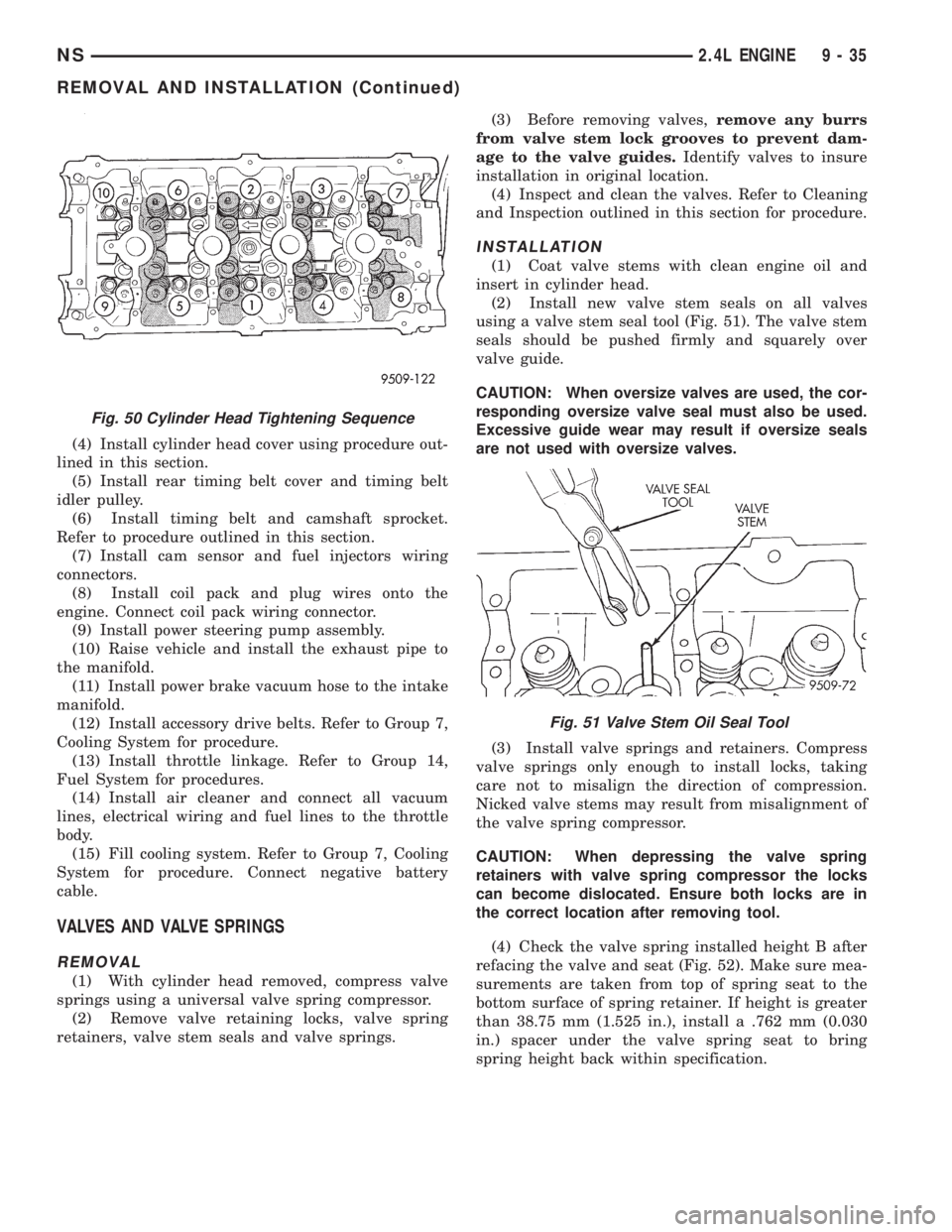
(2) Install new valve stem seals on all valves
using a valve stem seal tool (Fig. 51). The valve stem
seals should be pushed firmly and squarely over
valve guide.
CAUTION: When oversize valves are used, the cor-
responding oversize valve seal must also be used.
Excessive guide wear may result if oversize seals
are not used with oversize valves.
(3) Install valve springs and retainers. Compress
valve springs only enough to install locks, taking
care not to misalign the direction of compression.
Nicked valve stems may result from misalignment of
the valve spring compressor.
CAUTION: When depressing the valve spring
retainers with valve spring compressor the locks
can become dislocated. Ensure both locks are in
the correct location after removing tool.
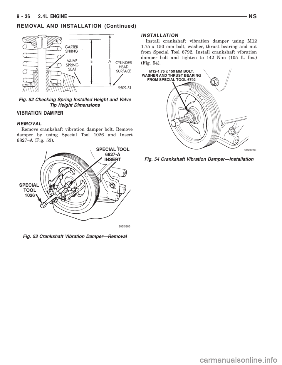
(4) Check the valve spring installed height B after
refacing the valve and seat (Fig. 52). Make sure mea-
surements are taken from top of spring seat to the
bottom surface of spring retainer. If height is greater
than 38.75 mm (1.525 in.), install a .762 mm (0.030
in.) spacer under the valve spring seat to bring
spring height back within specification.
Fig. 50 Cylinder Head Tightening Sequence
Fig. 51 Valve Stem Oil Seal Tool
NS2.4L ENGINE 9 - 35
REMOVAL AND INSTALLATION (Continued)
Page 1086 of 1938
VIBRATION DAMPER
REMOVAL
Remove crankshaft vibration damper bolt. Remove
damper by using Special Tool 1026 and Insert
6827±A (Fig. 53).
INSTALLATION
Install crankshaft vibration damper using M12
1.75 x 150 mm bolt, washer, thrust bearing and nut
from Special Tool 6792. Install crankshaft vibration
damper bolt and tighten to 142 N´m (105 ft. lbs.)
(Fig. 54).
Fig. 52 Checking Spring Installed Height and Valve
Tip Height Dimensions
Fig. 53 Crankshaft Vibration DamperÐRemoval
Fig. 54 Crankshaft Vibration DamperÐInstallation
9 - 36 2.4L ENGINENS
REMOVAL AND INSTALLATION (Continued)
Page 1101 of 1938
(4) Wash all parts in a suitable solvent and
inspect carefully for damage or wear.
ASSEMBLY
(1) Assemble pump, using new parts as required.
Install the inner rotor with chamfer facing the
cast iron oil pump cover.
(2) Prime oil pump before installation by filling
rotor cavity with engine oil.
(3) Install cover and tighten screws to 12 N´m
(105 in. lbs.).
CAUTION: Oil pump pressure relief valve must be
installed as shown in (Fig. 95) or serious damage
may occur.
(4) Install relief valve, spring, gasket and cap as
shown in (Fig. 95). Tighten cap to 41 N´m (30 ft. lbs.)
CLEANING AND INSPECTION
CYLINDER HEAD
CLEANING
Remove all gasket material from cylinder head and
block. Be careful not to gouge or scratch the alumi-
num head sealing surface.
INSPECTION
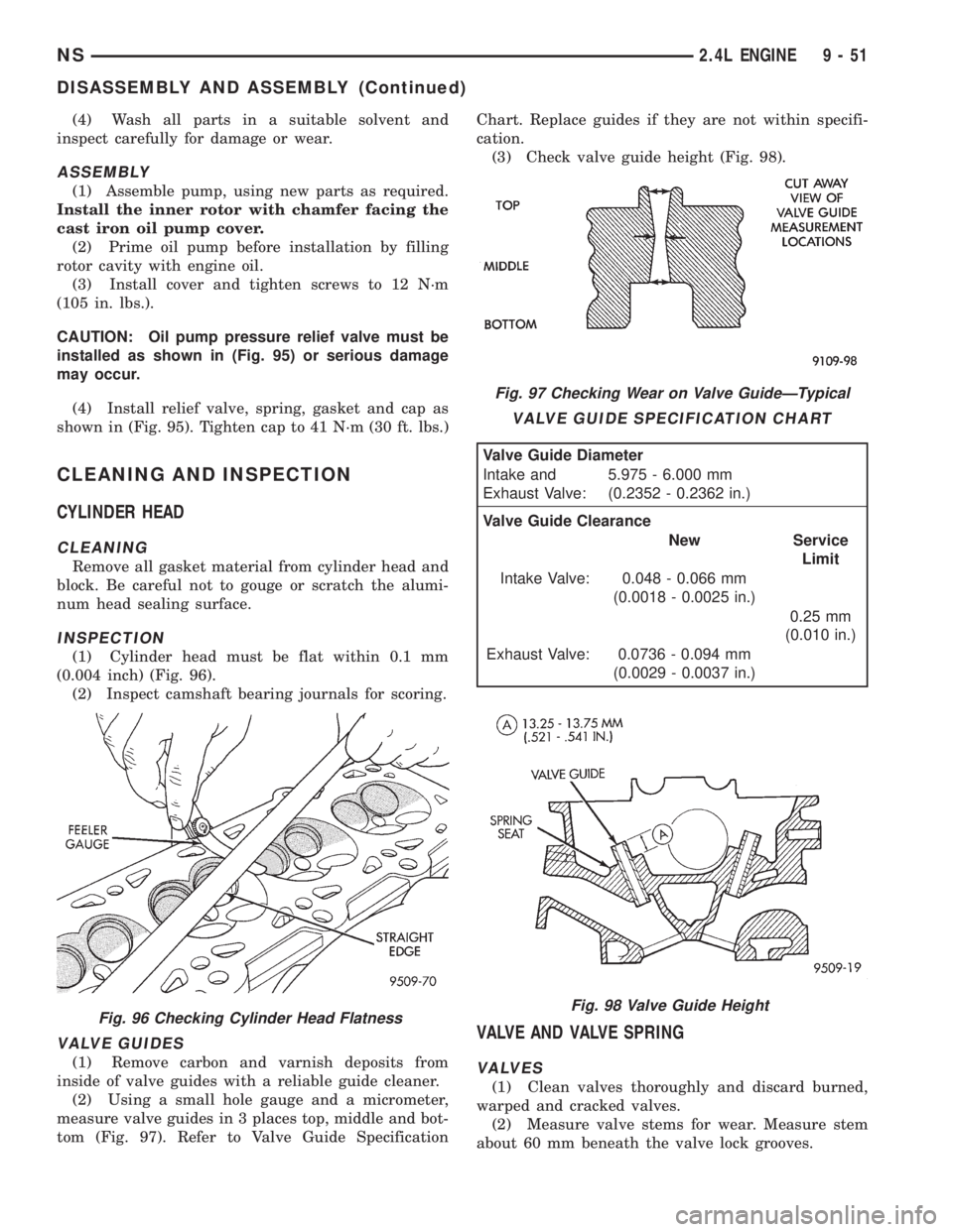
(1) Cylinder head must be flat within 0.1 mm
(0.004 inch) (Fig. 96).
(2) Inspect camshaft bearing journals for scoring.
VALVE GUIDES
(1) Remove carbon and varnish deposits from
inside of valve guides with a reliable guide cleaner.
(2) Using a small hole gauge and a micrometer,
measure valve guides in 3 places top, middle and bot-
tom (Fig. 97). Refer to Valve Guide SpecificationChart. Replace guides if they are not within specifi-
cation.
(3) Check valve guide height (Fig. 98).
VALVE AND VALVE SPRING
VALVES
(1) Clean valves thoroughly and discard burned,
warped and cracked valves.
(2) Measure valve stems for wear. Measure stem
about 60 mm beneath the valve lock grooves.
Fig. 96 Checking Cylinder Head Flatness
Fig. 97 Checking Wear on Valve GuideÐTypical
VALVE GUIDE SPECIFICATION CHART
Valve Guide Diameter
Intake and
Exhaust Valve:5.975 - 6.000 mm
(0.2352 - 0.2362 in.)
Valve Guide Clearance
New Service
Limit
Intake Valve: 0.048 - 0.066 mm
(0.0018 - 0.0025 in.)
0.25 mm
(0.010 in.)
Exhaust Valve: 0.0736 - 0.094 mm
(0.0029 - 0.0037 in.)
Fig. 98 Valve Guide Height
NS2.4L ENGINE 9 - 51
DISASSEMBLY AND ASSEMBLY (Continued)