1996 CHRYSLER VOYAGER height
[x] Cancel search: heightPage 1253 of 1938
CYLINDER HEAD
CLEANING
Thoroughly clean the engine cylinder head and cyl-
inder block mating surfaces. Clean the intake and
exhaust manifold and engine cylinder head mating
surfaces. Remove all gasket material and carbon.
Check to ensure that no coolant or foreign material
has fallen into the tappet bore area.
Remove the carbon deposits from the combustion
chambers and top of the pistons.
INSPECTION
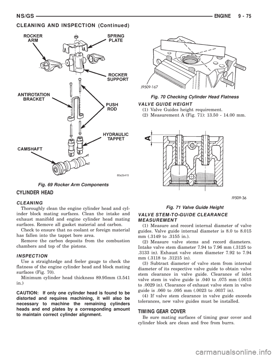
Use a straightedge and feeler gauge to check the
flatness of the engine cylinder head and block mating
surfaces (Fig. 70).
Minimum cylinder head thickness 89.95mm (3.541
in.)
CAUTION: If only one cylinder head is found to be
distorted and requires machining, it will also be
necessary to machine the remaining cylinders
heads and end plates by a corresponding amount
to maintain correct cylinder alignment.
VALVE GUIDE HEIGHT
(1) Valve Guides height requirement.
(2) Measurement A (Fig. 71): 13.50 - 14.00 mm.
VALVE STEM-TO-GUIDE CLEARANCE
MEASUREMENT
(1) Measure and record internal diameter of valve
guides. Valve guide internal diameter is 8.0 to 8.015
mm (.3149 to .3155 in.).
(2) Measure valve stems and record diameters.
Intake valve stem diameter 7.94 to 7.96 mm (.3125 to
.3133 in). Exhaust valve stem diameter 7.92 to 7.94
mm (.3118 to .31215 in).
(3) Subtract diameter of valve stem from internal
diameter of its respective valve guide to obtain valve
stem clearance in valve guide. Clearance of inlet
valve stem in valve guide is .040 to .075 mm (.0015
to .0029 in). Clearance of exhaust valve stem in valve
guide is .060 to .095 mm (.0023 to .0037 in).
(4) If valve stem clearance in valve guide exceeds
tolerances, new valve guides must be installed.
TIMING GEAR COVER
Be sure mating surfaces of timing gear cover and
cylinder block are clean and free from burrs.
Fig. 69 Rocker Arm Components
Fig. 70 Checking Cylinder Head Flatness
Fig. 71 Valve Guide Height
NS/GSENGINE 9 - 75
CLEANING AND INSPECTION (Continued)
Page 1254 of 1938

VALVES AND VALVE SPRINGS
VALVE CLEANING
Clean all carbon deposits from the combustion
chambers, valve ports, valve stems, valve stem
guides and heads.
Clean all grime and gasket material from the
engine cylinder head machined gasket surfaces.
INSPECTION
Inspect for cracks in the combustion chambers and
valve ports.
Inspect for cracks on the exhaust seat.
Inspect for cracks in the gasket surface at each
coolant passage.
Inspect valves for burned, cracked or warped
heads.
Inspect for scuffed or bent valve stems.
Replace valves displaying any damage.
Check valve spring height. (Fig. 72).
HYDRAULIC TAPPETS
(1) Clean all tappet parts in a solvent that will
remove all varnish and carbon.
(2) Replace tappets that are unfit for further ser-
vice with new assemblies.
(3) If plunger shows signs of scoring or wear,
install a new tappet assembly. If valve is pitted, or
valve seat on end of plunger is prevented from seat-
ing, install a new tappet assembly.
OIL PUMP
CLEANING
Wash all parts in a suitable solvent and inspect
carefully for damage or wear (Fig. 74).
INSPECTION
(1) Before installing oil pump check pump bore
depth in block (A) and pump body height (B) (Fig.
73). Difference between A and B should be
0.020-0.082 mm.
(2) Check clearance between rotors (Fig. 75).
PISTON AND CONNECTING ROD
PISTONS
(1) Piston Diameter: Size Group A: 91.93-91.94mm
(3.6191-3.6196 in.) Size Group B: 91.94-91.95mm
Fig. 72 Valve Spring Chart
Fig. 73 Oil Pump Bore Depth
Fig. 74 Oil Pump Inner and Outer Rotors
9 - 76 ENGINENS/GS
CLEANING AND INSPECTION (Continued)
Page 1257 of 1938
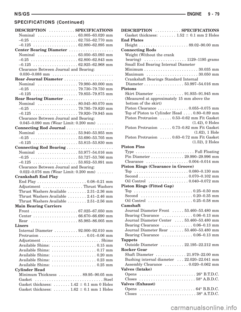
DESCRIPTION...........SPECIFICATIONS
Nominal.................63.005±63.020 mm
±0.25....................62.755±62.770 mm
±0.125...................62.880±62.895 mm
Center Bearing Diameter...................
Nominal.................63.050±63.093 mm
±0.25....................62.800±62.843 mm
±0.125...................62.925±62.968 mm
Clearance Between Journal and Bearing:
0.030±0.088 mm..........................
Rear Journal Diameter.....................
Nominal.................79.980±80.000 mm
±0.25....................79.730±79.750 mm
±0.125...................79.855±79.875 mm
Rear Bearing Diameter.....................
Nominal.................80.045±80.070 mm
±0.25....................79.795±79.820 mm
±0.125...................79.920±79.945 mm
Clearance Between Journal and Bearing:
0.045±0.090 mm (Wear Limit: 0.200 mm).......
Connecting Rod Journal....................
Nominal.................53.940±53.955 mm
±0.25....................53.690±53.705 mm
±0.125...................53.815±53.830 mm
Connecting Rod Bearing....................
Nominal.................53.977±54.016 mm
±0.25....................53.727±53.766 mm
±0.125...................53.852±53.891 mm
Clearance Between Journal and Bearing:
0.022±0.076 mm (Wear Limit: 0.200 mm).......
Crankshaft End Play
End Play.....................0.08±0.21 mm
Adjustment.................Thrust Washers
Thrust Washers Available........2.31±2.36 mm
Thrust Washers Available........2.41±2.46 mm
Thrust Washers Available........2.51±2.56 mm
Main Bearing Carriers
Front....................67.025±67.050 mm
Center...................66.670±66.690 mm
Rear....................85.985±86.005 mm
Liners
Internal Diameter..........92.000±92.010 mm
Protrusion....................0.01±0.06 mm
Adjustment.........................Shims
Available Shims:...................0.15 mm
Available Shims:...................0.17 mm
Available Shims:...................0.20 mm
Available Shims:...................0.23 mm
Available Shims:...................0.25 mm
Cylinder Head
Minimum Thickness..........89.95±90.05 mm
Gasket.............................Steel
Gasket thickness:.......1.4260.1 mm 0 Holes
Gasket thickness:.......1.6260.1 mm 1 HolesDESCRIPTION...........SPECIFICATIONS
Gasket thickness:.......1.5260.1 mm 2 Holes
End Plates
Height.....................89.02±90.00 mm
Connecting Rods
Weight (Without the crank
bearing)..................1129±1195 grams
Small End Bearing Internal Diameter
Minimum.......................30.035 mm
Maximum......................30.050 mm
Crankshaft Bearings Standard Internal
Diameter.................53.997±54.016 mm
Pistons
Skirt Diameter............91.935±91.945 mm
(Measured at approximately 15 mm above the
bottom of the skirt)
Piston Clearance.............0.055±0.075 mm
Top of Piston to Cylinder Head....0.80±0.89 mm
Piston Protrusion.....0.53±0.62 mm Fit Gasket
(1.42), 0 Holes
Piston Protrusion.....0.73±0.82 mm Fit Gasket
(1.62), 1 Hole
Piston Protrusion.....0.63±0.72 mm Fit Gasket
(1.52), 2 Holes
Piston Pins
Type .........................Full Floating
Pin Diameter..............29.990±29.996 mm
Clearance..................0.004±0.014 mm
Piston Rings (Clearance in Groove)
Top .......................0.080±0.130 mm
Second.....................0.070±0.102 mm
Oil Control.................0.040±0.072 mm
Piston Rings (Fitted Gap)
Top .........................0.25±0.50 mm
Second......................0.20±0.35 mm
Oil Control...................0.25±0.58 mm
Camshaft
Journal Diameter Front.....53.460±53.480 mm
Bearing Clearance.............0.06±0.13 mm
Journal Diameter Center....53.460±53.480 mm
Bearing Clearance.............0.06±0.13 mm
Journal Diameter Rear......53.460±53.480 mm
Bearing Clearance.............0.06±0.13 mm
Tappets
Outside Diameter..........22.195±22.212 mm
Rocker Gear
Shaft Diameter.............21.979±22.00 mm
Bushing internal diameter . . . 22.020±22.041 mm
Assembly Clearance..........0.020±0.062 mm
Valves (Intake)
Opens........................26ÉB.T.D.C.
Closes........................58ÉA.B.D.C.
Valves (Exhaust)
Opens........................64ÉB.B.D.C.
Closes........................38ÉA.T.D.C.
NS/GSENGINE 9 - 79
SPECIFICATIONS (Continued)
Page 1258 of 1938
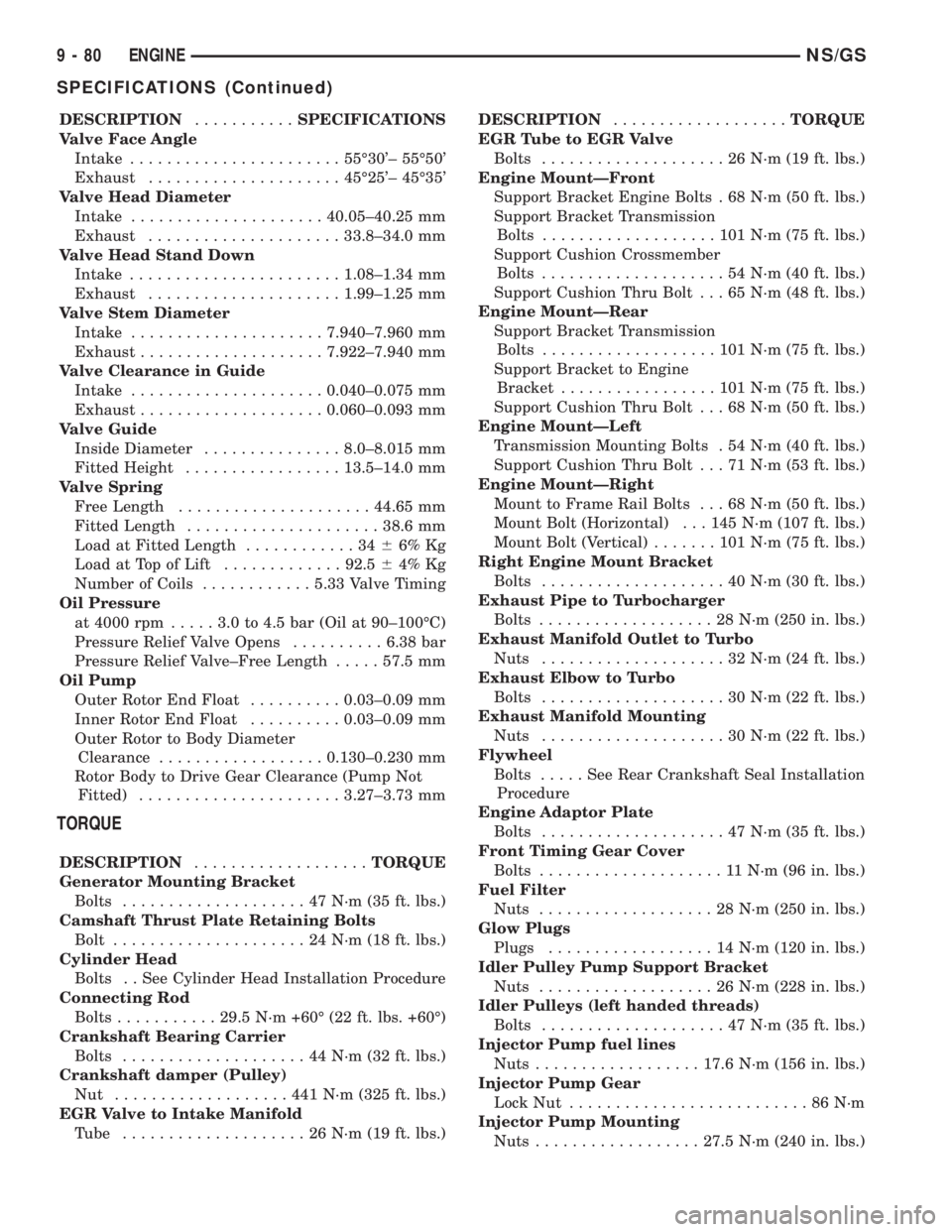
DESCRIPTION...........SPECIFICATIONS
Valve Face Angle
Intake.......................55É30'± 55É50'
Exhaust.....................45É25'± 45É35'
Valve Head Diameter
Intake.....................40.05±40.25 mm
Exhaust.....................33.8±34.0 mm
Valve Head Stand Down
Intake.......................1.08±1.34 mm
Exhaust.....................1.99±1.25 mm
Valve Stem Diameter
Intake.....................7.940±7.960 mm
Exhaust....................7.922±7.940 mm
Valve Clearance in Guide
Intake.....................0.040±0.075 mm
Exhaust....................0.060±0.093 mm
Valve Guide
Inside Diameter...............8.0±8.015 mm
Fitted Height.................13.5±14.0 mm
Valve Spring
Free Length.....................44.65 mm
Fitted Length.....................38.6 mm
Load at Fitted Length............3466% Kg
Load at Top of Lift.............92.564% Kg
Number of Coils............5.33 Valve Timing
Oil Pressure
at 4000 rpm.....3.0to4.5bar(Oil at 90±100ÉC)
Pressure Relief Valve Opens..........6.38 bar
Pressure Relief Valve±Free Length.....57.5 mm
Oil Pump
Outer Rotor End Float..........0.03±0.09 mm
Inner Rotor End Float..........0.03±0.09 mm
Outer Rotor to Body Diameter
Clearance..................0.130±0.230 mm
Rotor Body to Drive Gear Clearance (Pump Not
Fitted)......................3.27±3.73 mm
TORQUE
DESCRIPTION...................TORQUE
Generator Mounting Bracket
Bolts....................47N´m(35ft.lbs.)
Camshaft Thrust Plate Retaining Bolts
Bolt.....................24N´m(18ft.lbs.)
Cylinder Head
Bolts . . See Cylinder Head Installation Procedure
Connecting Rod
Bolts...........29.5 N´m +60É (22 ft. lbs. +60É)
Crankshaft Bearing Carrier
Bolts....................44N´m(32ft.lbs.)
Crankshaft damper (Pulley)
Nut ...................441N´m(325 ft. lbs.)
EGR Valve to Intake Manifold
Tube ....................26N´m(19ft.lbs.)DESCRIPTION...................TORQUE
EGR Tube to EGR Valve
Bolts....................26N´m(19ft.lbs.)
Engine MountÐFront
Support Bracket Engine Bolts . 68 N´m (50 ft. lbs.)
Support Bracket Transmission
Bolts...................101N´m(75ft.lbs.)
Support Cushion Crossmember
Bolts....................54N´m(40ft.lbs.)
Support Cushion Thru Bolt . . . 65 N´m (48 ft. lbs.)
Engine MountÐRear
Support Bracket Transmission
Bolts...................101N´m(75ft.lbs.)
Support Bracket to Engine
Bracket.................101N´m(75ft.lbs.)
Support Cushion Thru Bolt . . . 68 N´m (50 ft. lbs.)
Engine MountÐLeft
Transmission Mounting Bolts . 54 N´m (40 ft. lbs.)
Support Cushion Thru Bolt . . . 71 N´m (53 ft. lbs.)
Engine MountÐRight
Mount to Frame Rail Bolts . . . 68 N´m (50 ft. lbs.)
Mount Bolt (Horizontal) . . . 145 N´m (107 ft. lbs.)
Mount Bolt (Vertical).......101N´m(75ft.lbs.)
Right Engine Mount Bracket
Bolts....................40N´m(30ft.lbs.)
Exhaust Pipe to Turbocharger
Bolts...................28N´m(250 in. lbs.)
Exhaust Manifold Outlet to Turbo
Nuts....................32N´m(24ft.lbs.)
Exhaust Elbow to Turbo
Bolts....................30N´m(22ft.lbs.)
Exhaust Manifold Mounting
Nuts....................30N´m(22ft.lbs.)
Flywheel
Bolts.....SeeRear Crankshaft Seal Installation
Procedure
Engine Adaptor Plate
Bolts....................47N´m(35ft.lbs.)
Front Timing Gear Cover
Bolts....................11N´m(96in.lbs.)
Fuel Filter
Nuts...................28N´m(250 in. lbs.)
Glow Plugs
Plugs..................14N´m(120 in. lbs.)
Idler Pulley Pump Support Bracket
Nuts...................26N´m(228 in. lbs.)
Idler Pulleys (left handed threads)
Bolts....................47N´m(35ft.lbs.)
Injector Pump fuel lines
Nuts..................17.6 N´m (156 in. lbs.)
Injector Pump Gear
Lock Nut..........................86N´m
Injector Pump Mounting
Nuts..................27.5 N´m (240 in. lbs.)
9 - 80 ENGINENS/GS
SPECIFICATIONS (Continued)
Page 1285 of 1938
(7) Connect lower ball joints to lower control arms.
Refer to Group 2, Suspension.
(8) Connect stabilizer bar links to ends of stabi-
lizer bar. Refer to Group 2, Suspension.
(9) Install bolts to hold anti-lock brake sensor
leads to crossmember.
(10) Install high pressure hose to pump.
(11) Connect return hose to metal tube.
(12) Tighten hose clamp at the crossmember cou-
pling.
(13) Remove pinch-off pliers.
(14) Position steering so front wheels are straight
ahead.
(15) Install steering column coupling to telescoping
steering gear shaft.
(16) Install clinch bolt to hold steering column cou-
pling to steering gear shaft.
(17) Install knee blocker reinforcement. Refer to
Group 8E, Instrument Panel and Systems.
(18) Install steering column lower cover from
instrument panel. Refer to Group 8E, Instrument
Panel and Systems.
(19) Connect battery negative cable.
FRONT CROSSMEMBER MOUNT BUSHINGS
REMOVAL
(1) Using paint or grease pencil, mark outline of
crossmember on frame rails.
(2) Loosen bolts holding crossmember to frame
rails.
(3) Remove bolt on bushing that requires replace-
ment.
(4) Allow crossmember to drop down enough to
gain clearance for bushing removal.
(5) Remove bushing from vehicle.
INSTALLATION
(1) Apply rubber lube or soap to replacement bush-
ing.(2) Insert lower half of bushing into square hole in
crossmember.
(3) Place upper half of bushing on top of cross-
member aligned to receive square tube protruding
upward from lower bushing half.
(4) Squeeze bushing halves together to ensure they
are properly mated.
(5) Lift crossmember upward to close gap between
the bushing and frame.
(6) Verify that lower bushing is fully seated into
crossmember and upper bushing.
(7) Install bolt to hold bushing and crossmember
to frame rail hand tight.
(8) Align crossmember to reference marks on
frame rails.
(9) Tighten crossmember to frame rails attaching
bolts to 163 N´m (120 ft. lbs.) torque.
SPECIFICATIONS
FRAME AND BODY OPENING DIMENSIONS
Frame dimensions are listed in metric scale. All
dimensions are from center to center of Principal
Locating Point (PLP), or from center to center of PLP
and fastener location.
VEHICLE PREPARATION
Position the vehicle on a frame alignment rack,
refer to instructions provided with equipment being
used. Adjust the vehicle PLP heights to the specified
dimension above the work surface (datum line). Ver-
tical dimensions can be taken from the datum line to
the locations indicated were applicable. Refer to (Fig.
5), (Fig. 6), (Fig. 7), (Fig. 8), (Fig. 9), (Fig. 10) and
(Fig. 11) for proper dimensions.
NSFRAME AND BUMPERS 13 - 5
REMOVAL AND INSTALLATION (Continued)
Page 1423 of 1938
INSTALLATION
(1) Apply high±temperature anti±seize compound
to glow plug threads before installation
(2) Install the glow plug into the cylinder head.
Tighten to 23 N´m (203 in. lbs.) torque.
(3) Connect battery cable to battery.
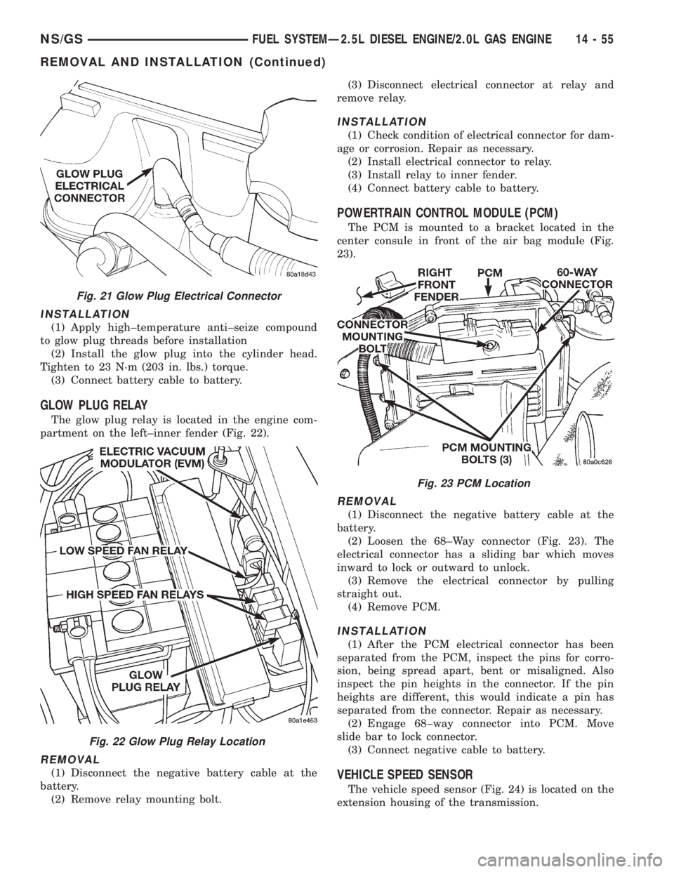
GLOW PLUG RELAY
The glow plug relay is located in the engine com-
partment on the left±inner fender (Fig. 22).
REMOVAL
(1) Disconnect the negative battery cable at the
battery.
(2) Remove relay mounting bolt.(3) Disconnect electrical connector at relay and
remove relay.
INSTALLATION
(1) Check condition of electrical connector for dam-
age or corrosion. Repair as necessary.
(2) Install electrical connector to relay.
(3) Install relay to inner fender.
(4) Connect battery cable to battery.
POWERTRAIN CONTROL MODULE (PCM)
The PCM is mounted to a bracket located in the
center consule in front of the air bag module (Fig.
23).
REMOVAL
(1) Disconnect the negative battery cable at the
battery.
(2) Loosen the 68±Way connector (Fig. 23). The
electrical connector has a sliding bar which moves
inward to lock or outward to unlock.
(3) Remove the electrical connector by pulling
straight out.
(4) Remove PCM.
INSTALLATION
(1) After the PCM electrical connector has been
separated from the PCM, inspect the pins for corro-
sion, being spread apart, bent or misaligned. Also
inspect the pin heights in the connector. If the pin
heights are different, this would indicate a pin has
separated from the connector. Repair as necessary.
(2) Engage 68±way connector into PCM. Move
slide bar to lock connector.
(3) Connect negative cable to battery.
VEHICLE SPEED SENSOR
The vehicle speed sensor (Fig. 24) is located on the
extension housing of the transmission.
Fig. 21 Glow Plug Electrical Connector
Fig. 22 Glow Plug Relay Location
Fig. 23 PCM Location
NS/GSFUEL SYSTEMÐ2.5L DIESEL ENGINE/2.0L GAS ENGINE 14 - 55
REMOVAL AND INSTALLATION (Continued)
Page 1753 of 1938
SHOULDER BELT HEIGHT ADJUSTER KNOB . . 64
SHOULDER BELT HEIGHT ADJUSTER±BOR
C-PILLAR............................ 64
SIDE VIEW MIRROR..................... 64
SLIDING DOOR CENTER HINGE............ 66
SLIDING DOOR CENTER STOP TRIM COVER . . 66
SLIDING DOOR CENTER STRIKER ASSEMBLY . 67
SLIDING DOOR HOLD OPEN LATCH STRIKER . 67
SLIDING DOOR HOLD OPEN LATCH......... 67
SLIDING DOOR INSIDE LATCH HANDLE
BELLCRANK.......................... 68
SLIDING DOOR INSIDE LATCH HANDLE...... 68
SLIDING DOOR INSIDE LATCH RELEASE
MECHANISM.......................... 69
SLIDING DOOR LATCH STRIKER........... 69
SLIDING DOOR LATCH/LOCK CONTROL..... 70
SLIDING DOOR LOWER ROLLER ARM
BRACKET............................ 71
SLIDING DOOR LOWER ROLLER ARM....... 71SLIDING DOOR OUTSIDE LATCH RELEASE
HANDLE............................. 72
SLIDING DOOR REAR LATCH.............. 73
SLIDING DOOR SILL PLATE............... 73
SLIDING DOOR STABILIZER SOCKET........ 74
SLIDING DOOR STABILIZER............... 73
SLIDING DOOR STOP BUMPER............ 74
SLIDING DOOR TRIM PANEL............... 74
SLIDING DOOR UPPER ROLLER............ 75
SLIDING DOOR WEATHER-STRIP........... 75
SLIDING DOOR......................... 64
STICK-ON BODY SIDE MOLDING........... 75
SUN VISOR SUPPORT................... 78
SUN VISOR............................ 76
UPPER B-PILLAR TRIM COVER............. 78
UPPER C-PILLAR TRIM................... 80
ADJUSTMENTS
SLIDING DOOR ADJUSTMENTS............ 80
DIAGNOSIS AND TESTING
WATER LEAKS
Water leaks can be caused by poor sealing,
improper body component alignment, body seam
porosity, missing plugs, or blocked drain holes. Cen-
trifugal and gravitational force can cause water to
drip from a location away from the actual leak point,
making leak detection difficult. All body sealing
points should be water tight in normal wet-driving
conditions. Water flowing downward from the front of
the vehicle should not enter the passenger or luggage
compartment. Moving sealing surfaces will not
always seal water tight under all conditions. At
times, side glass or door seals will allow water to
enter the passenger compartment during high pres-
sure washing or hard driving rain (severe) condi-
tions. Overcompensating on door or glass
adjustments to stop a water leak that occurs under
severe conditions can cause premature seal wear and
excessive closing or latching effort. After completing
a repair, water-test vehicle to verify leak has stopped
before returning vehicle to use.
VISUAL INSPECTION BEFORE WATER LEAK
TESTS
Verify that floor and body plugs are in place, body
drains are clear, and body components are properly
aligned and sealed. If component alignment or seal-
ing is necessary, refer to the appropriate section of
this group for proper procedures.
WATER LEAK TESTS
WARNING: DO NOT USE ELECTRIC SHOP LIGHTS
OR TOOLS IN WATER TEST AREA. PERSONAL
INJURY CAN RESULT.When the conditions causing a water leak have
been determined, simulate the conditions as closely
as possible.
²If a leak occurs with the vehicle parked in a
steady light rain, flood the leak area with an open-
ended garden hose.
²If a leak occurs while driving at highway speeds
in a steady rain, test the leak area with a reasonable
velocity stream or fan spray of water. Direct the
spray in a direction comparable to actual conditions.
²If a leak occurs when the vehicle is parked on an
incline, hoist the end or side of the vehicle to simu-
late this condition. This method can be used when
the leak occurs when the vehicle accelerates, stops or
turns. If the leak occurs on acceleration, hoist the
front of the vehicle. If the leak occurs when braking,
hoist the back of the vehicle. If the leak occurs on left
turns, hoist the left side of the vehicle. If the leak
occurs on right turns, hoist the right side of the vehi-
cle. For hoisting recommendations refer to Group 0,
Lubrication and Maintenance, General Information
section.
WATER LEAK DETECTION
To detect a water leak point-of-entry, do a water
test and watch for water tracks or droplets forming
on the inside of the vehicle. If necessary, remove inte-
rior trim covers or panels to gain visual access to the
leak area. If the hose cannot be positioned without
being held, have someone help do the water test.
NSBODY 23 - 23
Page 1771 of 1938
to support the hood, install bottom bolts to hold hood
to hinge finger tight.
(2) Install top bolts to hold hood to hinge finger
tight.
(3) Position bolts at marks and tighten bolts. The
hood should be aligned to 4 mm (0.160 in.) gap to the
front fenders and flush across the top surfaces along
fenders.
(4) Verify hood operation and alignment.
HOOD HINGE
REMOVAL
(1) Remove hood.
(2) Remove wiper unit. Refer to Group 8K, Wind-
shield Wipers and Washers, for procedure.
(3) Mark all bolt and hinge attachment locations
with a grease pencil or other suitable device to pro-
vide reference marks for installation.
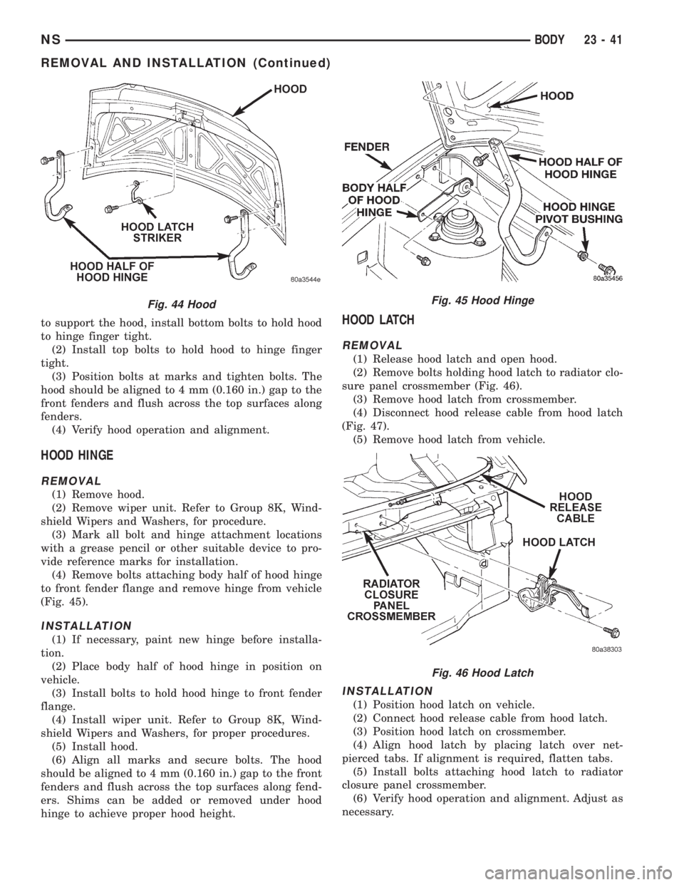
(4) Remove bolts attaching body half of hood hinge
to front fender flange and remove hinge from vehicle
(Fig. 45).
INSTALLATION
(1) If necessary, paint new hinge before installa-
tion.
(2) Place body half of hood hinge in position on
vehicle.
(3) Install bolts to hold hood hinge to front fender
flange.
(4) Install wiper unit. Refer to Group 8K, Wind-
shield Wipers and Washers, for proper procedures.
(5) Install hood.
(6) Align all marks and secure bolts. The hood
should be aligned to 4 mm (0.160 in.) gap to the front
fenders and flush across the top surfaces along fend-
ers. Shims can be added or removed under hood
hinge to achieve proper hood height.
HOOD LATCH
REMOVAL
(1) Release hood latch and open hood.
(2) Remove bolts holding hood latch to radiator clo-
sure panel crossmember (Fig. 46).
(3) Remove hood latch from crossmember.
(4) Disconnect hood release cable from hood latch
(Fig. 47).
(5) Remove hood latch from vehicle.
INSTALLATION
(1) Position hood latch on vehicle.
(2) Connect hood release cable from hood latch.
(3) Position hood latch on crossmember.
(4) Align hood latch by placing latch over net-
pierced tabs. If alignment is required, flatten tabs.
(5) Install bolts attaching hood latch to radiator
closure panel crossmember.
(6) Verify hood operation and alignment. Adjust as
necessary.
Fig. 44 HoodFig. 45 Hood Hinge
Fig. 46 Hood Latch
NSBODY 23 - 41
REMOVAL AND INSTALLATION (Continued)