1996 CHRYSLER VOYAGER height
[x] Cancel search: heightPage 1789 of 1938
(3) Remove side cover from seat.
(4) Remove bolts attaching recliner bracket to seat
cushion.
(5) Remove recliner bracket from seat.
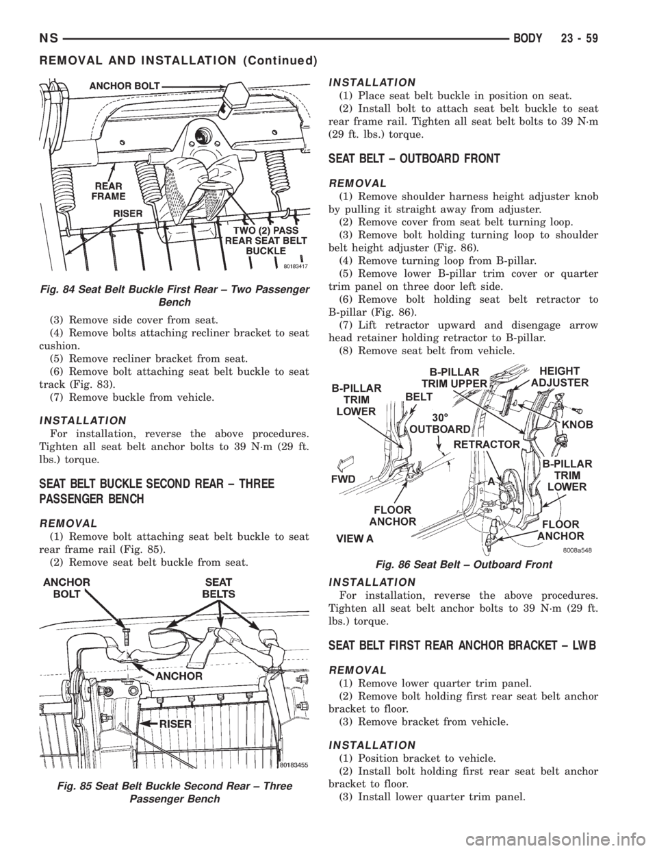
(6) Remove bolt attaching seat belt buckle to seat
track (Fig. 83).
(7) Remove buckle from vehicle.
INSTALLATION
For installation, reverse the above procedures.
Tighten all seat belt anchor bolts to 39 N´m (29 ft.
lbs.) torque.
SEAT BELT BUCKLE SECOND REAR ± THREE
PASSENGER BENCH
REMOVAL
(1) Remove bolt attaching seat belt buckle to seat
rear frame rail (Fig. 85).
(2) Remove seat belt buckle from seat.
INSTALLATION
(1) Place seat belt buckle in position on seat.
(2) Install bolt to attach seat belt buckle to seat
rear frame rail. Tighten all seat belt bolts to 39 N´m
(29 ft. lbs.) torque.
SEAT BELT ± OUTBOARD FRONT
REMOVAL
(1) Remove shoulder harness height adjuster knob
by pulling it straight away from adjuster.
(2) Remove cover from seat belt turning loop.
(3) Remove bolt holding turning loop to shoulder
belt height adjuster (Fig. 86).
(4) Remove turning loop from B-pillar.
(5) Remove lower B-pillar trim cover or quarter
trim panel on three door left side.
(6) Remove bolt holding seat belt retractor to
B-pillar (Fig. 86).
(7) Lift retractor upward and disengage arrow
head retainer holding retractor to B-pillar.
(8) Remove seat belt from vehicle.
INSTALLATION
For installation, reverse the above procedures.
Tighten all seat belt anchor bolts to 39 N´m (29 ft.
lbs.) torque.
SEAT BELT FIRST REAR ANCHOR BRACKET ± LWB
REMOVAL
(1) Remove lower quarter trim panel.
(2) Remove bolt holding first rear seat belt anchor
bracket to floor.
(3) Remove bracket from vehicle.
INSTALLATION
(1) Position bracket to vehicle.
(2) Install bolt holding first rear seat belt anchor
bracket to floor.
(3) Install lower quarter trim panel.
Fig. 84 Seat Belt Buckle First Rear ± Two Passenger
Bench
Fig. 85 Seat Belt Buckle Second Rear ± Three
Passenger Bench
Fig. 86 Seat Belt ± Outboard Front
NSBODY 23 - 59
REMOVAL AND INSTALLATION (Continued)
Page 1790 of 1938
NOTE: The tightening specification for all seat belt
anchor bolts is 39 N´m (29 ft. lbs.) torque.
SEAT BELT FIRST REAR OUTBOARD ± LWB FOUR
DOOR
REMOVAL
(1) Remove first and second rear seats. Refer to
Owner's manual for proper procedures.
(2) Remove shoulder harness height adjuster knob
by pulling it straight away from adjuster.
(3) Slide floor anchor cover from over the anchor
bolt.
(4) Remove floor anchor bolt.
(5) Remove anchor from floor.
(6) Open clam shell cover from over seat belt turn-
ing loop.
(7) Remove bolt holding turning loop to shoulder
belt height adjuster.
(8) Remove turning loop from C-pillar.
(9) Remove lower quarter trim panel.
(10) Route seat belt webbing and turning loop
through access hole in lower quarter trim panel.
(11) Remove bolt holding seat belt retractor to
quarter panel.
(12) Lift retractor upward and disengage arrow
head retainer holding retractor to quarter panel.
(13) Remove seat belt from vehicle.
INSTALLATION
(1) Position seat belt to vehicle.
(2) Install arrow head retainer to quarter panel
and push downward to seat retainer.
(3) Install bolt holding seat belt retractor to quar-
ter panel.
(4) Route seat belt webbing and turning loop
through access hole in lower quarter trim panel.
(5) Install lower quarter trim panel.
(6) Position turning loop to C-pillar.
(7) Install bolt holding turning loop to shoulder
belt height adjuster.
(8) Close clam shell cover from over seat belt turn-
ing loop.
(9) Position anchor to floor.
(10) Install floor anchor bolt.
(11) Slide floor anchor cover over the anchor bolt.
(12) Install shoulder harness height adjuster knob
by pushing it straight onto adjuster.
(13) Install first and second rear seats. Refer to
Owner's manual for proper procedures.
NOTE: The tightening specification for all seat belt
anchor bolts is 39 N´m (29 ft. lbs.) torque.
SEAT BELT FIRST REAR OUTBOARD ± SWB FOUR
DOOR
REMOVAL
(1) Remove first and second rear seats. Refer to
Owner's manual for proper procedures.
(2) Remove shoulder harness height adjuster knob
by pulling it straight away from adjuster.
(3) Slide floor anchor cover from over the anchor
bolt.
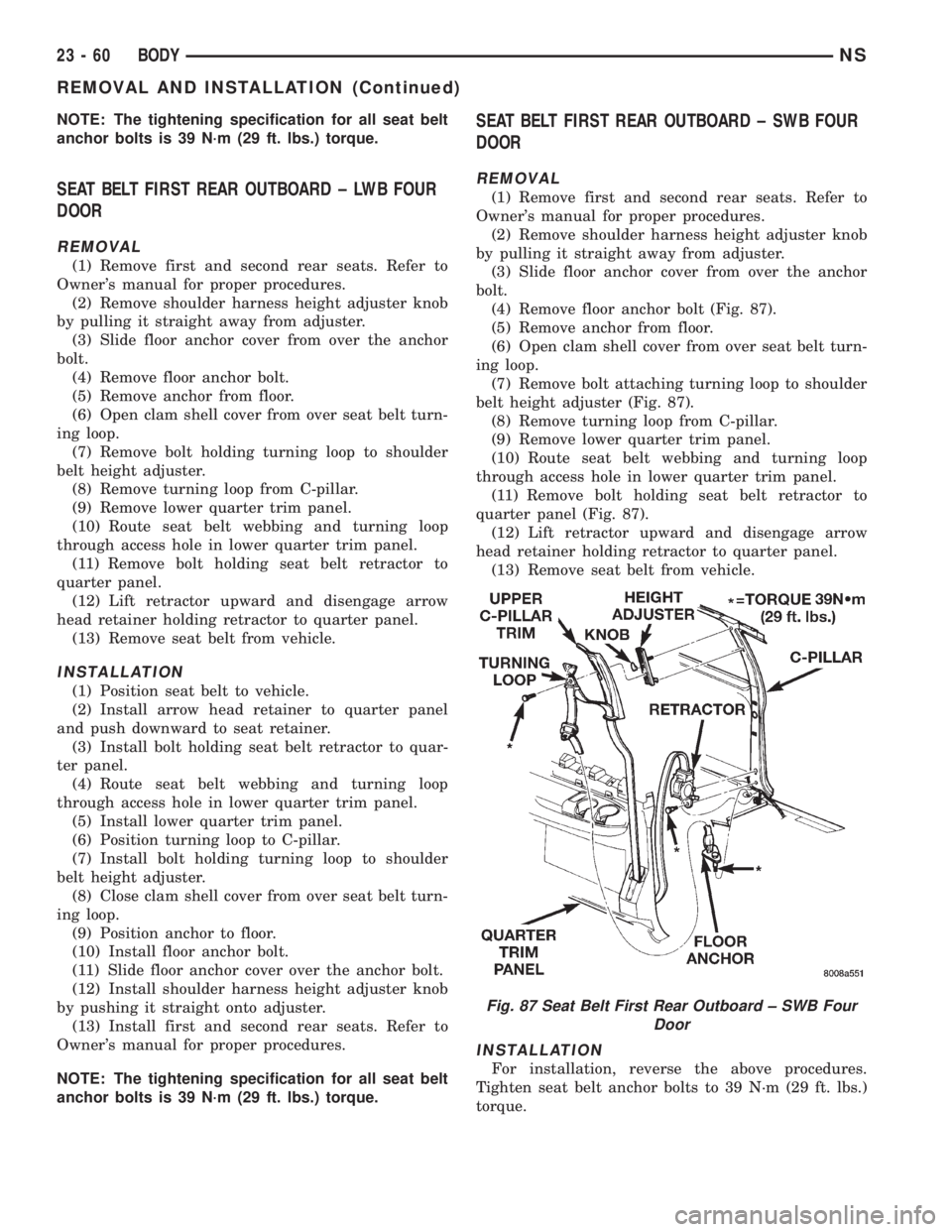
(4) Remove floor anchor bolt (Fig. 87).
(5) Remove anchor from floor.
(6) Open clam shell cover from over seat belt turn-
ing loop.
(7) Remove bolt attaching turning loop to shoulder
belt height adjuster (Fig. 87).
(8) Remove turning loop from C-pillar.
(9) Remove lower quarter trim panel.
(10) Route seat belt webbing and turning loop
through access hole in lower quarter trim panel.
(11) Remove bolt holding seat belt retractor to
quarter panel (Fig. 87).
(12) Lift retractor upward and disengage arrow
head retainer holding retractor to quarter panel.
(13) Remove seat belt from vehicle.
INSTALLATION
For installation, reverse the above procedures.
Tighten seat belt anchor bolts to 39 N´m (29 ft. lbs.)
torque.
Fig. 87 Seat Belt First Rear Outboard ± SWB Four
Door
23 - 60 BODYNS
REMOVAL AND INSTALLATION (Continued)
Page 1791 of 1938
SEAT BELT LEFT FIRST REAR OUTBOARD ± LWB
THREE DOOR
REMOVAL
(1) Remove first and second rear seats. Refer to
Owner's manual for proper procedures.
(2) Remove shoulder harness height adjuster knob
by pulling it straight away from adjuster.
(3) Slide floor anchor cover from over the anchor
bolt.
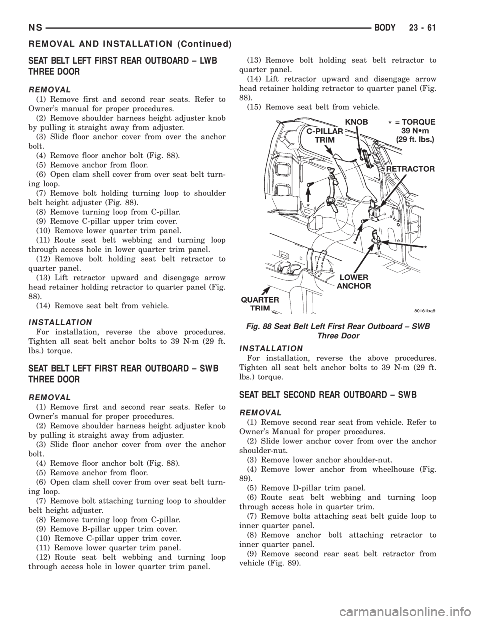
(4) Remove floor anchor bolt (Fig. 88).
(5) Remove anchor from floor.
(6) Open clam shell cover from over seat belt turn-
ing loop.
(7) Remove bolt holding turning loop to shoulder
belt height adjuster (Fig. 88).
(8) Remove turning loop from C-pillar.
(9) Remove C-pillar upper trim cover.
(10) Remove lower quarter trim panel.
(11) Route seat belt webbing and turning loop
through access hole in lower quarter trim panel.
(12) Remove bolt holding seat belt retractor to
quarter panel.
(13) Lift retractor upward and disengage arrow
head retainer holding retractor to quarter panel (Fig.
88).
(14) Remove seat belt from vehicle.
INSTALLATION
For installation, reverse the above procedures.
Tighten all seat belt anchor bolts to 39 N´m (29 ft.
lbs.) torque.
SEAT BELT LEFT FIRST REAR OUTBOARD ± SWB
THREE DOOR
REMOVAL
(1) Remove first and second rear seats. Refer to
Owner's manual for proper procedures.
(2) Remove shoulder harness height adjuster knob
by pulling it straight away from adjuster.
(3) Slide floor anchor cover from over the anchor
bolt.
(4) Remove floor anchor bolt (Fig. 88).
(5) Remove anchor from floor.
(6) Open clam shell cover from over seat belt turn-
ing loop.
(7) Remove bolt attaching turning loop to shoulder
belt height adjuster.
(8) Remove turning loop from C-pillar.
(9) Remove B-pillar upper trim cover.
(10) Remove C-pillar upper trim cover.
(11) Remove lower quarter trim panel.
(12) Route seat belt webbing and turning loop
through access hole in lower quarter trim panel.(13) Remove bolt holding seat belt retractor to
quarter panel.
(14) Lift retractor upward and disengage arrow
head retainer holding retractor to quarter panel (Fig.
88).
(15) Remove seat belt from vehicle.
INSTALLATION
For installation, reverse the above procedures.
Tighten all seat belt anchor bolts to 39 N´m (29 ft.
lbs.) torque.
SEAT BELT SECOND REAR OUTBOARD ± SWB
REMOVAL
(1) Remove second rear seat from vehicle. Refer to
Owner's Manual for proper procedures.
(2) Slide lower anchor cover from over the anchor
shoulder-nut.
(3) Remove lower anchor shoulder-nut.
(4) Remove lower anchor from wheelhouse (Fig.
89).
(5) Remove D-pillar trim panel.
(6) Route seat belt webbing and turning loop
through access hole in quarter trim.
(7) Remove bolts attaching seat belt guide loop to
inner quarter panel.
(8) Remove anchor bolt attaching retractor to
inner quarter panel.
(9) Remove second rear seat belt retractor from
vehicle (Fig. 89).
Fig. 88 Seat Belt Left First Rear Outboard ± SWB
Three Door
NSBODY 23 - 61
REMOVAL AND INSTALLATION (Continued)
Page 1794 of 1938
SHOULDER BELT HEIGHT ADJUSTER±BOR
C-PILLAR
REMOVAL
(1) Remove B or C-pillar trim cover.
(2) Remove screws holding shoulder belt height
adjuster to pillar.
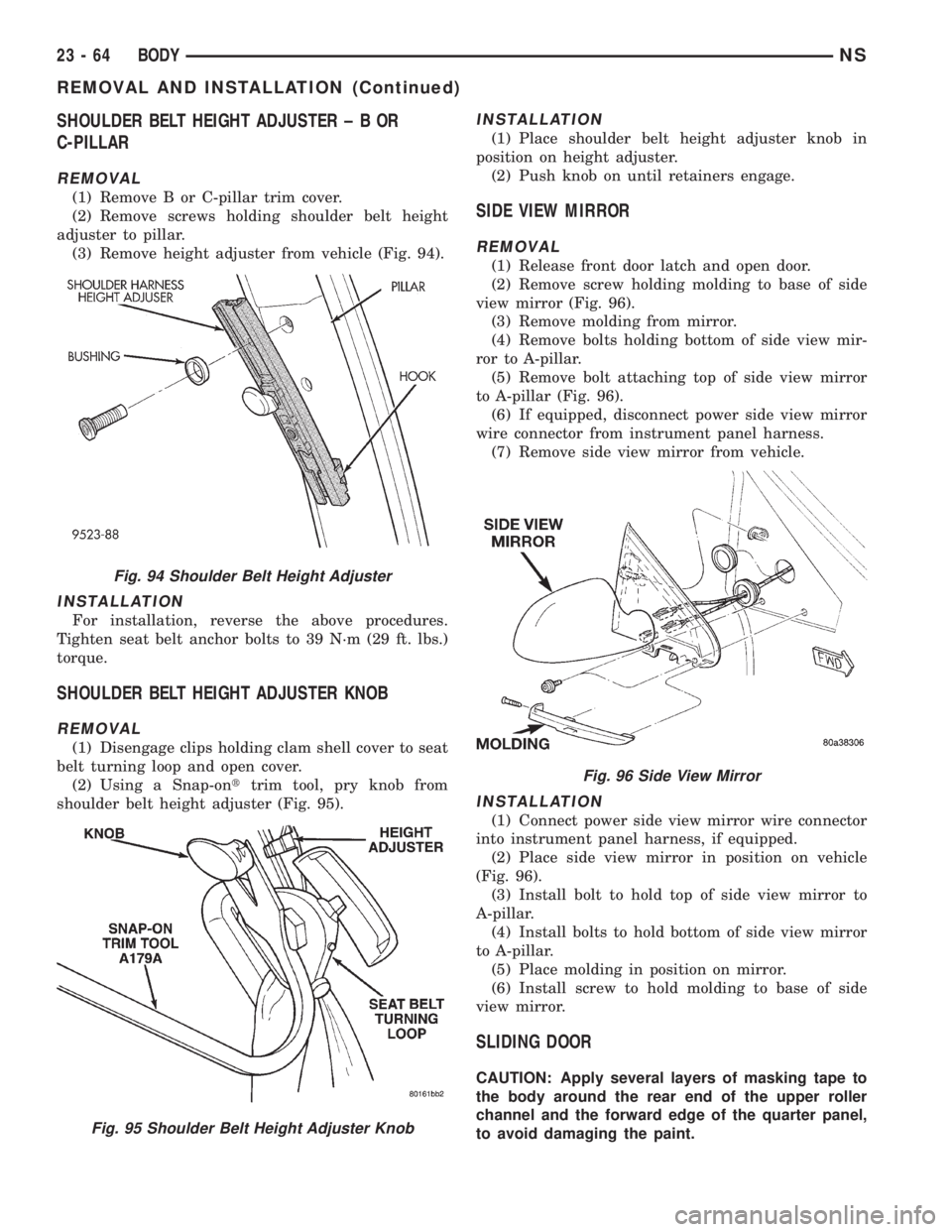
(3) Remove height adjuster from vehicle (Fig. 94).
INSTALLATION
For installation, reverse the above procedures.
Tighten seat belt anchor bolts to 39 N´m (29 ft. lbs.)
torque.
SHOULDER BELT HEIGHT ADJUSTER KNOB
REMOVAL
(1) Disengage clips holding clam shell cover to seat
belt turning loop and open cover.
(2) Using a Snap-onttrim tool, pry knob from
shoulder belt height adjuster (Fig. 95).
INSTALLATION
(1) Place shoulder belt height adjuster knob in
position on height adjuster.
(2) Push knob on until retainers engage.
SIDE VIEW MIRROR
REMOVAL
(1) Release front door latch and open door.
(2) Remove screw holding molding to base of side
view mirror (Fig. 96).
(3) Remove molding from mirror.
(4) Remove bolts holding bottom of side view mir-
ror to A-pillar.
(5) Remove bolt attaching top of side view mirror
to A-pillar (Fig. 96).
(6) If equipped, disconnect power side view mirror
wire connector from instrument panel harness.
(7) Remove side view mirror from vehicle.
INSTALLATION
(1) Connect power side view mirror wire connector
into instrument panel harness, if equipped.
(2) Place side view mirror in position on vehicle
(Fig. 96).
(3) Install bolt to hold top of side view mirror to
A-pillar.
(4) Install bolts to hold bottom of side view mirror
to A-pillar.
(5) Place molding in position on mirror.
(6) Install screw to hold molding to base of side
view mirror.
SLIDING DOOR
CAUTION: Apply several layers of masking tape to
the body around the rear end of the upper roller
channel and the forward edge of the quarter panel,
to avoid damaging the paint.
Fig. 94 Shoulder Belt Height Adjuster
Fig. 95 Shoulder Belt Height Adjuster Knob
Fig. 96 Side View Mirror
23 - 64 BODYNS
REMOVAL AND INSTALLATION (Continued)
Page 1808 of 1938
INSTALLATION
(1) Place sun visor in position on vehicle.
(2) Connect illuminated vanity mirror wire connec-
tor into body harness.
(3) Place sun visor in position on roof.
(4) Install screws to hold sun visor to roof header
(Fig. 134).
(5) Engage sun visor into center support.
SUN VISOR SUPPORT
REMOVAL
(1) Disengage sun visor from support.
(2) Remove screw holding support to roof header
(Fig. 135).
(3) Remove sun visor support from vehicle.
INSTALLATION
(1) Place sun visor support in position on vehicle.
(2) Install screw holding support to roof header
(Fig. 135).
(3) Engage sun visor into support.
UPPER B-PILLAR TRIM COVER
REMOVAL
(1) Remove bolt holding lower seat belt anchor to
floor.
(2) Lower shoulder belt height adjuster to the bot-
tom of travel.
(3) Remove shoulder belt turning loop from height
adjuster.
(4) Using Snap-ontprying tool (A179A), or equiv-
alent, remove shoulder belt height adjuster knob.
(5) Remove shoulder belt bezel from trim cover.
(6) Remove screw holding trim cover to B-pillar
from inside bezel cavity.
(7) Disengage hidden clips holding trim cover to
B-pillar.
(8) Remove B-pillar trim cover from vehicle (Fig.
136).
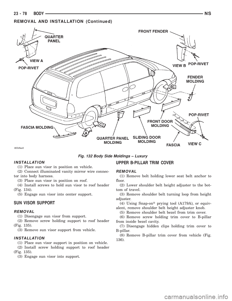
Fig. 132 Body Side Moldings ± Luxury
23 - 78 BODYNS
REMOVAL AND INSTALLATION (Continued)
Page 1809 of 1938
INSTALLATION
(1) Insert seat belt through B-pillar trim and web
guide.
(2) Place B-pillar trim cover in position on vehicle.
(3) Engage hidden clips to hold trim cover to B-pil-
lar.
(4) Install screw to hold trim cover to B-pillar
inside bezel cavity.
(5) Install shoulder belt bezel into trim cover.(6) Install height adjuster knob.
(7) Install shoulder belt turning loop onto height
adjuster.
(8) Place seat anchor in position on floor so web-
bing is pointed rearward and slightly outboard.
(9) Install bolt to hold lower seat belt anchor to
floor. Tighten seat belt bolts to 39 N´m (29 in. lbs.)
torque.
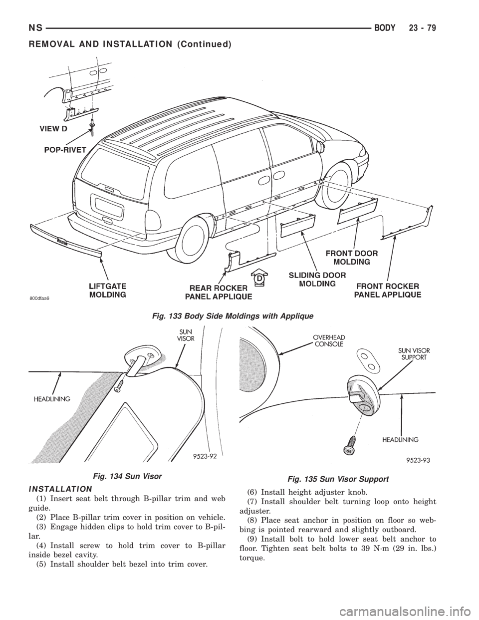
Fig. 133 Body Side Moldings with Applique
Fig. 134 Sun VisorFig. 135 Sun Visor Support
NSBODY 23 - 79
REMOVAL AND INSTALLATION (Continued)
Page 1810 of 1938
UPPER C-PILLAR TRIM
REMOVAL
(1) Remove quarter trim bolster.
(2) Remove seat belt turning loop from height
adjuster.
(3) Remove screw holding C-pillar trim panel to
C-pillar on right side of SWB vehicle.
(4) Disengage hidden clips holding trim to upper
C-pillar.
(5) Remove upper C-pillar trim from vehicle.
INSTALLATION
(1) Place upper C-pillar trim in position on vehicle.
(2) Engage hidden clips to hold trim to upper
C-pillar.
(3) Install screw to hold C-pillar trim panel to
C-pillar on right side of SWB vehicle.
(4) Install seat belt turning loop onto height
adjuster. Tighten all seat belt bolts to 39 N´m (29 in.
lbs.) torque.
(5) Install quarter trim bolster.
ADJUSTMENTS
SLIDING DOOR ADJUSTMENTS
PRELIMINARY CHECKS
(1) Close sliding door, visually checking C-post
striker alignment entry into latch. Striker at this
point must not affect alignment.(2) On vehicles with left sliding doors, check the
fuel door blocker striker entry into latch. Striker at
this point must not affect alignment.
(3) Check C-post and B-post for door to aperture
gaps and door to door gaps. All gaps should be 5 mm
61 mm.
(4) C
heck door for height using character lines as a
reference. Also check roof contour as a controlling factor.
UP/DOWN ADJUSTMENT
(1) Visually inspect the sliding door for fitting low
at the rear of the door by checking the alignment of
the belt line of the door to quarter panel.
(2) Fully open the sliding door.
(3) Verify that all center hinge bolts are tight.
(4) Adjust the rear of the sliding door up by turn-
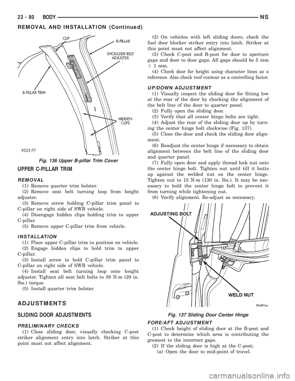
ing the center hinge bolt clockwise (Fig. 137).
(5) Close the door and check the sliding door align-
ment.
(6) Readjust the center hinge if necessary to obtain
alignment between the belt line of the sliding door
and quarter panel.
(7) Fully open door and apply thread lock nut onto
the center hinge bolt. Tighten nut until till it butts
up against the welded nut on the center hinge.
Tighten nut to 15 N´m (130 in. lbs.). It may be nec-
essary to hold the center hinge bolt to prevent it
from turning while tightening nut.
(8) Verify alignment. Re-adjust as necessary.
FORE/AFT ADJUSTMENT
(1) Check height of sliding door at the B-post and
C-post to determine which area is contributing the
greatest to the incorrect gaps.
(2) If the sliding door is high at the C-post;
(a) Open the door to mid-point of travel.
Fig. 136 Upper B-pillar Trim Cover
Fig. 137 Sliding Door Center Hinge
23 - 80 BODYNS
REMOVAL AND INSTALLATION (Continued)