1996 CHRYSLER VOYAGER sensor
[x] Cancel search: sensorPage 1310 of 1938
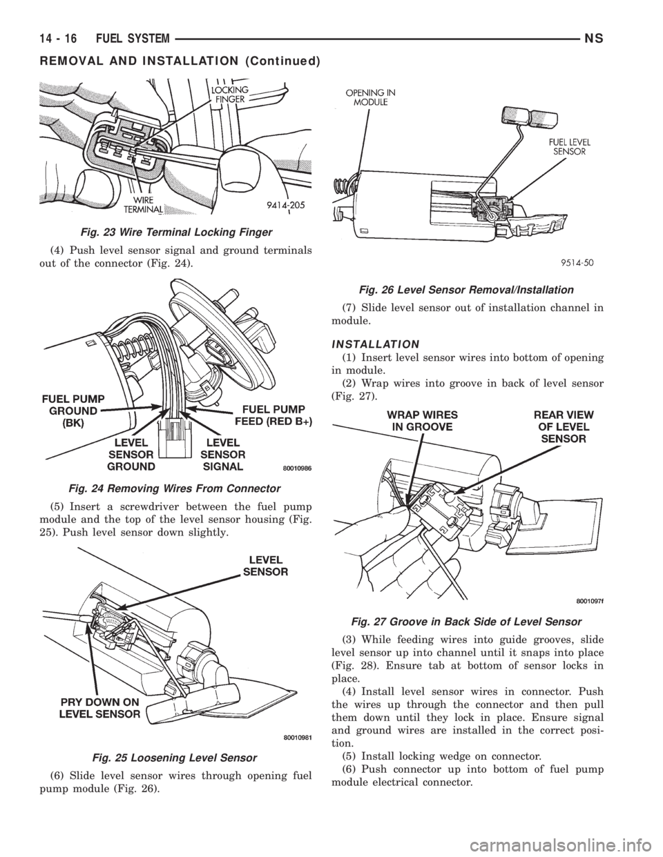
(4) Push level sensor signal and ground terminals
out of the connector (Fig. 24).
(5) Insert a screwdriver between the fuel pump
module and the top of the level sensor housing (Fig.
25). Push level sensor down slightly.
(6) Slide level sensor wires through opening fuel
pump module (Fig. 26).(7) Slide level sensor out of installation channel in
module.
INSTALLATION
(1) Insert level sensor wires into bottom of opening
in module.
(2) Wrap wires into groove in back of level sensor
(Fig. 27).
(3) While feeding wires into guide grooves, slide
level sensor up into channel until it snaps into place
(Fig. 28). Ensure tab at bottom of sensor locks in
place.
(4) Install level sensor wires in connector. Push
the wires up through the connector and then pull
them down until they lock in place. Ensure signal
and ground wires are installed in the correct posi-
tion.
(5) Install locking wedge on connector.
(6) Push connector up into bottom of fuel pump
module electrical connector.
Fig. 23 Wire Terminal Locking Finger
Fig. 24 Removing Wires From Connector
Fig. 25 Loosening Level Sensor
Fig. 26 Level Sensor Removal/Installation
Fig. 27 Groove in Back Side of Level Sensor
14 - 16 FUEL SYSTEMNS
REMOVAL AND INSTALLATION (Continued)
Page 1312 of 1938
INSTALLATION
(1) Position fuel tank on transmission jack. Con-
nect pressure relief/rollover valve hose. Connect fuel
filler tube vent hose and replace clamp.
(2) Raise tank into position and carefully work
filler tube into tank. A light coating of clean engine
oil on the tube end may be used to aid assembly.
(3) Feed filler vent line thru frame rail. Careful
not to cross lines.
(4) Tighten strap bolts to 54 N´m (40 ft. lbs.)
torque. Remove transmission jack.
(5) Tighten filler hose clamp to 3.3 N´m (30 in.
lbs.).
CAUTION: Ensure straps are not twisted or bent
before or after tightening strap nuts.
(6) Connect fuel pump/module electrical connector.
Place retainer in locked position.
(7) Lubricate the fuel supply line with clean 30
weight engine oil, install the quick connect fuel fit-
ting. Refer to Tube/Fitting Assembly in the Fuel
Delivery section of this Group.
(8) Attach filler line to filler tube. Pull on connec-
tor to make sure of connection.
(9) Fill fuel tank, replace cap, and connect battery
negative cable.
CAUTION: When using the ASD Fuel System Test,
the ASD relay and fuel pump relay remain energized
for 7 minutes or until the test is stopped, or until
the ignition switch is turned to the Off position.
(10) Use the DRB scan tool ASD Fuel System Test
to pressurize the fuel system. Check for leaks.
FUEL INJECTOR RAILÐ2.4L
REMOVAL
(1) Perform fuel system pressure release procedure
before servicing or starting repairs.Refer to
Fuel System Pressure Release Procedure in this sec-
tion.
(2) Disconnect negative cable from battery.
(3) Remove air cleaner inlet hose from throttle
body.
(4) Remove throttle cable and speed control cable
(if equipped) from throttle lever.
(5) Remove throttle cables from bracket by com-
pressing retaining tabs.
(6) Remove connector from throttle position sensor.
(7) Remove connector from idle air control motor.
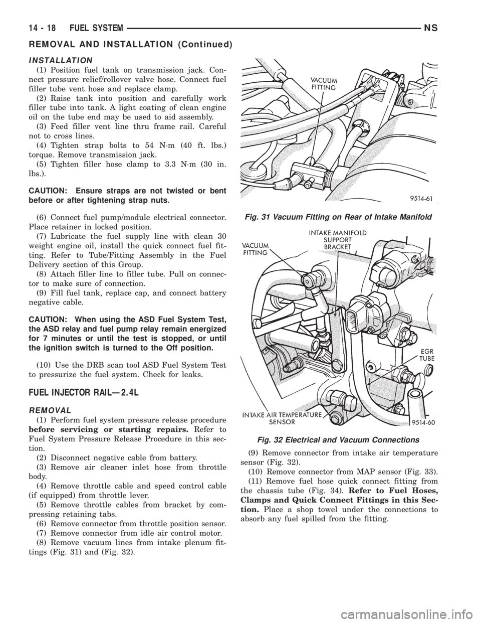
(8) Remove vacuum lines from intake plenum fit-
tings (Fig. 31) and (Fig. 32).(9) Remove connector from intake air temperature
sensor (Fig. 32).
(10) Remove connector from MAP sensor (Fig. 33).
(11) Remove fuel hose quick connect fitting from
the chassis tube (Fig. 34).Refer to Fuel Hoses,
Clamps and Quick Connect Fittings in this Sec-
tion.Place a shop towel under the connections to
absorb any fuel spilled from the fitting.
Fig. 31 Vacuum Fitting on Rear of Intake Manifold
Fig. 32 Electrical and Vacuum Connections
14 - 18 FUEL SYSTEMNS
REMOVAL AND INSTALLATION (Continued)
Page 1313 of 1938
WARNING: WRAP A SHOP TOWEL AROUND
HOSES TO CATCH ANY GASOLINE SPILLAGE.
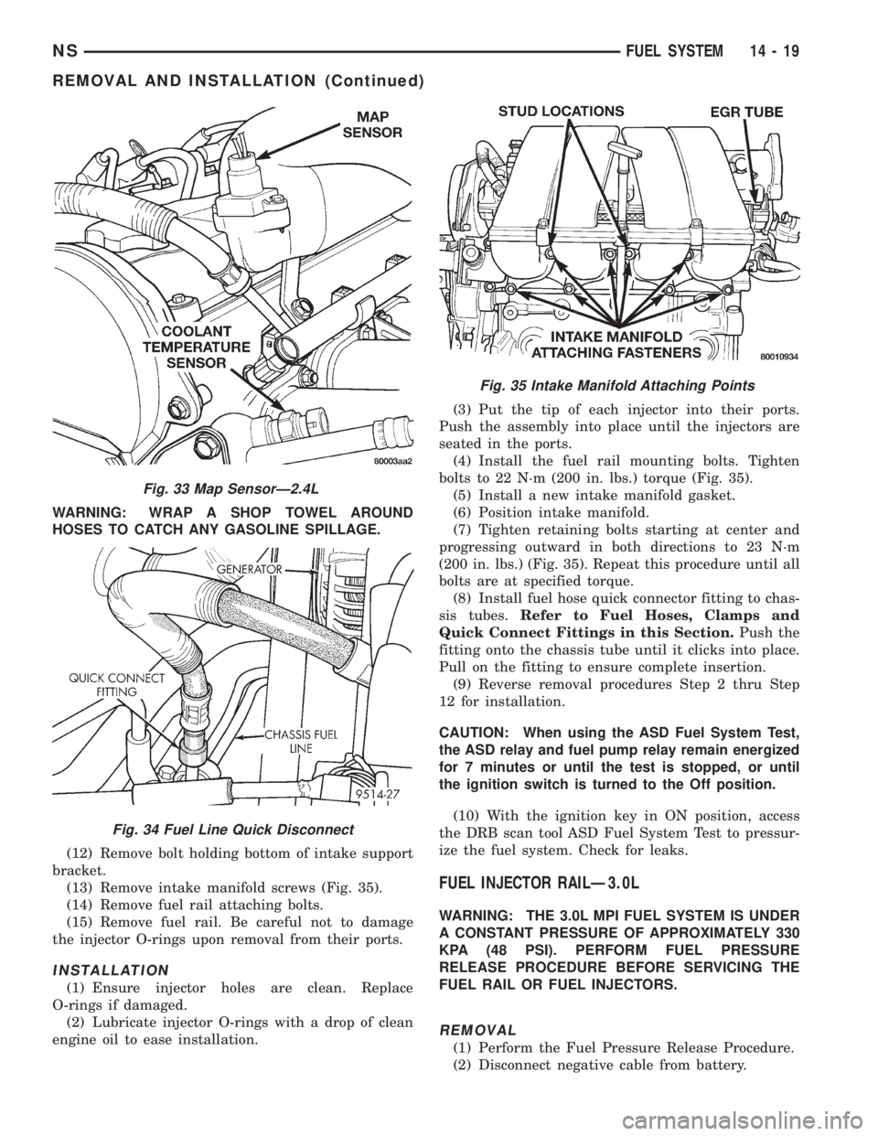
(12) Remove bolt holding bottom of intake support
bracket.
(13) Remove intake manifold screws (Fig. 35).
(14) Remove fuel rail attaching bolts.
(15) Remove fuel rail. Be careful not to damage
the injector O-rings upon removal from their ports.
INSTALLATION
(1) Ensure injector holes are clean. Replace
O-rings if damaged.
(2) Lubricate injector O-rings with a drop of clean
engine oil to ease installation.(3) Put the tip of each injector into their ports.
Push the assembly into place until the injectors are
seated in the ports.
(4) Install the fuel rail mounting bolts. Tighten
bolts to 22 N´m (200 in. lbs.) torque (Fig. 35).
(5) Install a new intake manifold gasket.
(6) Position intake manifold.
(7) Tighten retaining bolts starting at center and
progressing outward in both directions to 23 N´m
(200 in. lbs.) (Fig. 35). Repeat this procedure until all
bolts are at specified torque.
(8) Install fuel hose quick connector fitting to chas-
sis tubes.Refer to Fuel Hoses, Clamps and
Quick Connect Fittings in this Section.Push the
fitting onto the chassis tube until it clicks into place.
Pull on the fitting to ensure complete insertion.
(9) Reverse removal procedures Step 2 thru Step
12 for installation.
CAUTION: When using the ASD Fuel System Test,
the ASD relay and fuel pump relay remain energized
for 7 minutes or until the test is stopped, or until
the ignition switch is turned to the Off position.
(10) With the ignition key in ON position, access
the DRB scan tool ASD Fuel System Test to pressur-
ize the fuel system. Check for leaks.
FUEL INJECTOR RAILÐ3.0L
WARNING: THE 3.0L MPI FUEL SYSTEM IS UNDER
A CONSTANT PRESSURE OF APPROXIMATELY 330
KPA (48 PSI). PERFORM FUEL PRESSURE
RELEASE PROCEDURE BEFORE SERVICING THE
FUEL RAIL OR FUEL INJECTORS.
REMOVAL
(1) Perform the Fuel Pressure Release Procedure.
(2) Disconnect negative cable from battery.
Fig. 33 Map SensorÐ2.4L
Fig. 34 Fuel Line Quick Disconnect
Fig. 35 Intake Manifold Attaching Points
NSFUEL SYSTEM 14 - 19
REMOVAL AND INSTALLATION (Continued)
Page 1314 of 1938
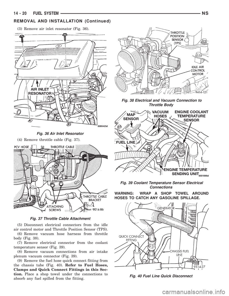
(3) Remove air inlet resonator (Fig. 36).
(4) Remove throttle cable (Fig. 37).
(5) Disconnect electrical connectors from the idle
air control motor and Throttle Position Sensor (TPS).
(6) Remove vacuum hose harness from throttle
body (Fig. 38).
(7) Remove electrical connector from the coolant
temperature sensor (Fig. 39).
(8) Remove vacuum connections from air intake
plenum vacuum connector (Fig. 39).
(9) Remove the fuel hose quick connect fitting from
the chassis tube (Fig. 40).Refer to Fuel Hoses,
Clamps and Quick Connect Fittings in this Sec-
tion.Place a shop towel under the connections to
absorb any fuel spilled from the fitting.WARNING: WRAP A SHOP TOWEL AROUND
HOSES TO CATCH ANY GASOLINE SPILLAGE.
Fig. 36 Air Inlet Resonator
Fig. 37 Throttle Cable Attachment
Fig. 38 Electrical and Vacuum Connection to
Throttle Body
Fig. 39 Coolant Temperature Sensor Electrical
Connections
Fig. 40 Fuel Line Quick Disconnect
14 - 20 FUEL SYSTEMNS
REMOVAL AND INSTALLATION (Continued)
Page 1315 of 1938
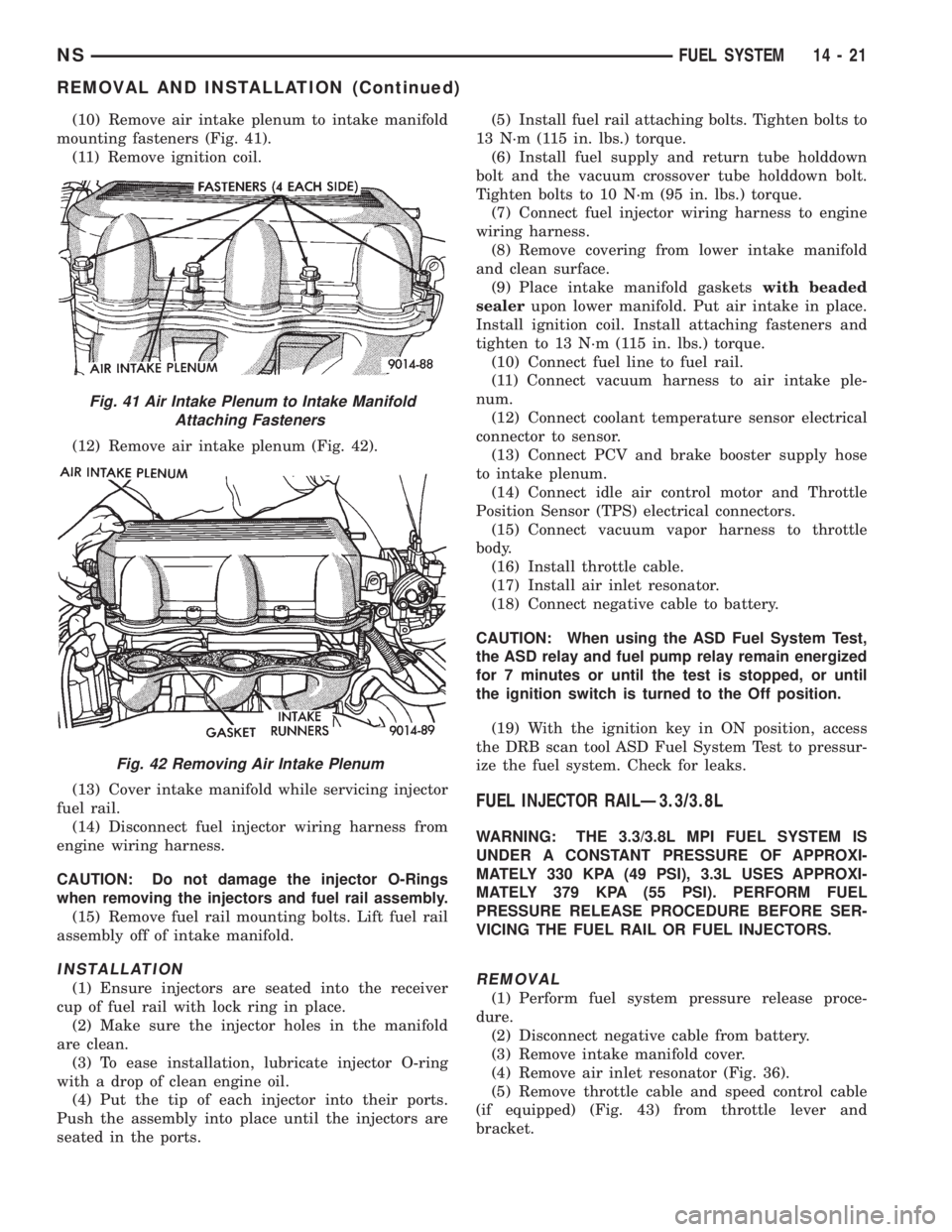
(10) Remove air intake plenum to intake manifold
mounting fasteners (Fig. 41).
(11) Remove ignition coil.
(12) Remove air intake plenum (Fig. 42).
(13) Cover intake manifold while servicing injector
fuel rail.
(14) Disconnect fuel injector wiring harness from
engine wiring harness.
CAUTION: Do not damage the injector O-Rings
when removing the injectors and fuel rail assembly.
(15) Remove fuel rail mounting bolts. Lift fuel rail
assembly off of intake manifold.
INSTALLATION
(1) Ensure injectors are seated into the receiver
cup of fuel rail with lock ring in place.
(2) Make sure the injector holes in the manifold
are clean.
(3) To ease installation, lubricate injector O-ring
with a drop of clean engine oil.
(4) Put the tip of each injector into their ports.
Push the assembly into place until the injectors are
seated in the ports.(5) Install fuel rail attaching bolts. Tighten bolts to
13 N´m (115 in. lbs.) torque.
(6) Install fuel supply and return tube holddown
bolt and the vacuum crossover tube holddown bolt.
Tighten bolts to 10 N´m (95 in. lbs.) torque.
(7) Connect fuel injector wiring harness to engine
wiring harness.
(8) Remove covering from lower intake manifold
and clean surface.
(9) Place intake manifold gasketswith beaded
sealerupon lower manifold. Put air intake in place.
Install ignition coil. Install attaching fasteners and
tighten to 13 N´m (115 in. lbs.) torque.
(10) Connect fuel line to fuel rail.
(11) Connect vacuum harness to air intake ple-
num.
(12) Connect coolant temperature sensor electrical
connector to sensor.
(13) Connect PCV and brake booster supply hose
to intake plenum.
(14) Connect idle air control motor and Throttle
Position Sensor (TPS) electrical connectors.
(15) Connect vacuum vapor harness to throttle
body.
(16) Install throttle cable.
(17) Install air inlet resonator.
(18) Connect negative cable to battery.
CAUTION: When using the ASD Fuel System Test,
the ASD relay and fuel pump relay remain energized
for 7 minutes or until the test is stopped, or until
the ignition switch is turned to the Off position.
(19) With the ignition key in ON position, access
the DRB scan tool ASD Fuel System Test to pressur-
ize the fuel system. Check for leaks.
FUEL INJECTOR RAILÐ3.3/3.8L
WARNING: THE 3.3/3.8L MPI FUEL SYSTEM IS
UNDER A CONSTANT PRESSURE OF APPROXI-
MATELY 330 KPA (49 PSI), 3.3L USES APPROXI-
MATELY 379 KPA (55 PSI). PERFORM FUEL
PRESSURE RELEASE PROCEDURE BEFORE SER-
VICING THE FUEL RAIL OR FUEL INJECTORS.
REMOVAL
(1) Perform fuel system pressure release proce-
dure.
(2) Disconnect negative cable from battery.
(3) Remove intake manifold cover.
(4) Remove air inlet resonator (Fig. 36).
(5) Remove throttle cable and speed control cable
(if equipped) (Fig. 43) from throttle lever and
bracket.
Fig. 41 Air Intake Plenum to Intake Manifold
Attaching Fasteners
Fig. 42 Removing Air Intake Plenum
NSFUEL SYSTEM 14 - 21
REMOVAL AND INSTALLATION (Continued)
Page 1316 of 1938
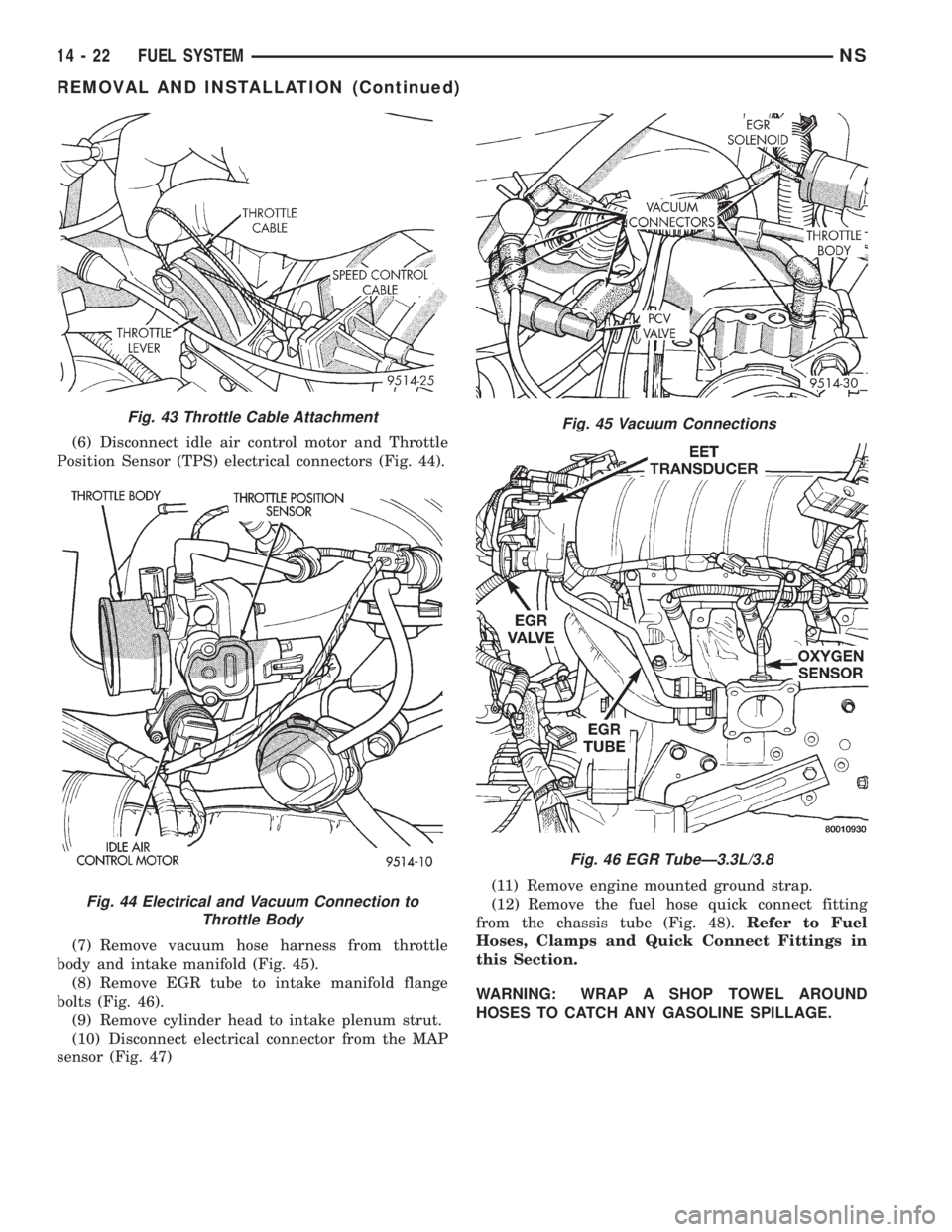
(6) Disconnect idle air control motor and Throttle
Position Sensor (TPS) electrical connectors (Fig. 44).
(7) Remove vacuum hose harness from throttle
body and intake manifold (Fig. 45).
(8) Remove EGR tube to intake manifold flange
bolts (Fig. 46).
(9) Remove cylinder head to intake plenum strut.
(10) Disconnect electrical connector from the MAP
sensor (Fig. 47)(11) Remove engine mounted ground strap.
(12) Remove the fuel hose quick connect fitting
from the chassis tube (Fig. 48).Refer to Fuel
Hoses, Clamps and Quick Connect Fittings in
this Section.
WARNING: WRAP A SHOP TOWEL AROUND
HOSES TO CATCH ANY GASOLINE SPILLAGE.
Fig. 43 Throttle Cable Attachment
Fig. 44 Electrical and Vacuum Connection to
Throttle Body
Fig. 45 Vacuum Connections
Fig. 46 EGR TubeÐ3.3L/3.8
14 - 22 FUEL SYSTEMNS
REMOVAL AND INSTALLATION (Continued)
Page 1317 of 1938
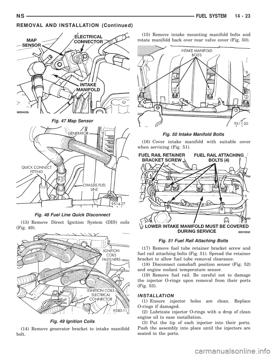
(13) Remove Direct Ignition System (DIS) coils
(Fig. 49).
(14) Remove generator bracket to intake manifold
bolt.(15) Remove intake mounting manifold bolts and
rotate manifold back over rear valve cover (Fig. 50).
(16) Cover intake manifold with suitable cover
when servicing (Fig. 51).
(17) Remove fuel tube retainer bracket screw and
fuel rail attaching bolts (Fig. 51). Spread the retainer
bracket to allow fuel tube removal clearance.
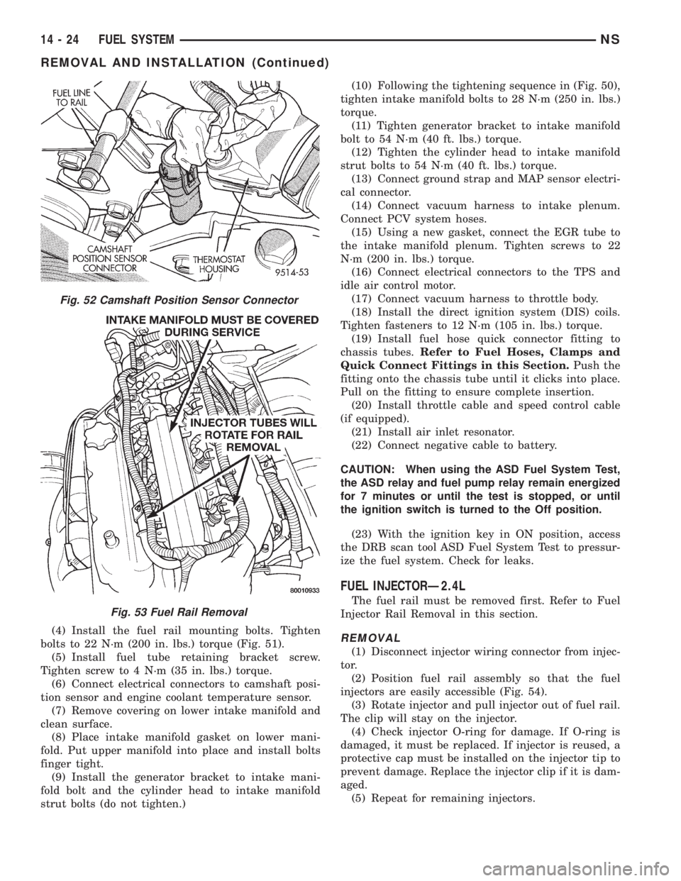
(18) Disconnect camshaft position sensor (Fig. 52)
and engine coolant temperature sensor.
(19) Remove fuel rail. Be careful not to damage
the injector O-rings upon removal from their ports
(Fig. 53).
INSTALLATION
(1) Ensure injector holes are clean. Replace
O-rings if damaged.
(2) Lubricate injector O-rings with a drop of clean
engine oil to ease installation.
(3) Put the tip of each injector into their ports.
Push the assembly into place until the injectors are
seated in the ports.
Fig. 47 Map Sensor
Fig. 48 Fuel Line Quick Disconnect
Fig. 49 Ignition Coils
Fig. 50 Intake Manifold Bolts
Fig. 51 Fuel Rail Attaching Bolts
NSFUEL SYSTEM 14 - 23
REMOVAL AND INSTALLATION (Continued)
Page 1318 of 1938
(4) Install the fuel rail mounting bolts. Tighten
bolts to 22 N´m (200 in. lbs.) torque (Fig. 51).
(5) Install fuel tube retaining bracket screw.
Tighten screw to 4 N´m (35 in. lbs.) torque.
(6) Connect electrical connectors to camshaft posi-
tion sensor and engine coolant temperature sensor.
(7) Remove covering on lower intake manifold and
clean surface.
(8) Place intake manifold gasket on lower mani-
fold. Put upper manifold into place and install bolts
finger tight.
(9) Install the generator bracket to intake mani-
fold bolt and the cylinder head to intake manifold
strut bolts (do not tighten.)(10) Following the tightening sequence in (Fig. 50),
tighten intake manifold bolts to 28 N´m (250 in. lbs.)
torque.
(11) Tighten generator bracket to intake manifold
bolt to 54 N´m (40 ft. lbs.) torque.
(12) Tighten the cylinder head to intake manifold
strut bolts to 54 N´m (40 ft. lbs.) torque.
(13) Connect ground strap and MAP sensor electri-
cal connector.
(14) Connect vacuum harness to intake plenum.
Connect PCV system hoses.
(15) Using a new gasket, connect the EGR tube to
the intake manifold plenum. Tighten screws to 22
N´m (200 in. lbs.) torque.
(16) Connect electrical connectors to the TPS and
idle air control motor.
(17) Connect vacuum harness to throttle body.
(18) Install the direct ignition system (DIS) coils.
Tighten fasteners to 12 N´m (105 in. lbs.) torque.
(19) Install fuel hose quick connector fitting to
chassis tubes.Refer to Fuel Hoses, Clamps and
Quick Connect Fittings in this Section.Push the
fitting onto the chassis tube until it clicks into place.
Pull on the fitting to ensure complete insertion.
(20) Install throttle cable and speed control cable
(if equipped).
(21) Install air inlet resonator.
(22) Connect negative cable to battery.
CAUTION: When using the ASD Fuel System Test,
the ASD relay and fuel pump relay remain energized
for 7 minutes or until the test is stopped, or until
the ignition switch is turned to the Off position.
(23) With the ignition key in ON position, access
the DRB scan tool ASD Fuel System Test to pressur-
ize the fuel system. Check for leaks.
FUEL INJECTORÐ2.4L
The fuel rail must be removed first. Refer to Fuel
Injector Rail Removal in this section.
REMOVAL
(1) Disconnect injector wiring connector from injec-
tor.
(2) Position fuel rail assembly so that the fuel
injectors are easily accessible (Fig. 54).
(3) Rotate injector and pull injector out of fuel rail.
The clip will stay on the injector.
(4) Check injector O-ring for damage. If O-ring is
damaged, it must be replaced. If injector is reused, a
protective cap must be installed on the injector tip to
prevent damage. Replace the injector clip if it is dam-
aged.
(5) Repeat for remaining injectors.
Fig. 52 Camshaft Position Sensor Connector
Fig. 53 Fuel Rail Removal
14 - 24 FUEL SYSTEMNS
REMOVAL AND INSTALLATION (Continued)