1996 CHRYSLER VOYAGER propeller shaft
[x] Cancel search: propeller shaftPage 1154 of 1938
ENGINE MOUNT RUBBER INSULATORS
Insulator location on (right side) is adjustable to
allow right/left drive train adjustment in relation to
drive shaft assembly length.
Check and reposition right engine mount insulator.
See Adjustments in this section. Adjust drive train
position, if required, for the following conditions:
a. Drive shaft distress. See Group 2, Suspension
and Driveshafts.
b. Any front end structural damage (after repair).
c. Insulator replacement.
ENGINE ASSEMBLY
REMOVAL
(1) Perform fuel pressure release procedure. Refer
to group 14 fuel system for procedure. Remove fuel
line to fuel rail.
(2) Disconnect battery.
(3) Remove air cleaner and hoses.
(4) Remove battery cover, battery and battery tray,
with integral vacuum reservoir, from vehicle.
(5) Block off heater hoses to rear heater assembly,
if equipped.
(6) Drain cooling system. Refer to Group 7, Cooling
System for procedure.
(7) Disconnect heater hoses.
(8) Remove fan module and radiator. Refer to
Group 7 Cooling System for procedure.
(9) Disconnect transmission shift linkage.
(10) Disconnect throttle body linkage and vacuum
hoses from throttle body.
(11) Remove accessory drive belts. Refer to Group
7, Accessory Drive Belts located in Cooling System
for procedure.
(12) Remove air conditioning compressor from
engine and set it aside.
(13) Disconnect generator wiring harness and
remove generator.
(14) Hoist vehicle and remove right and left inner
splash shields.
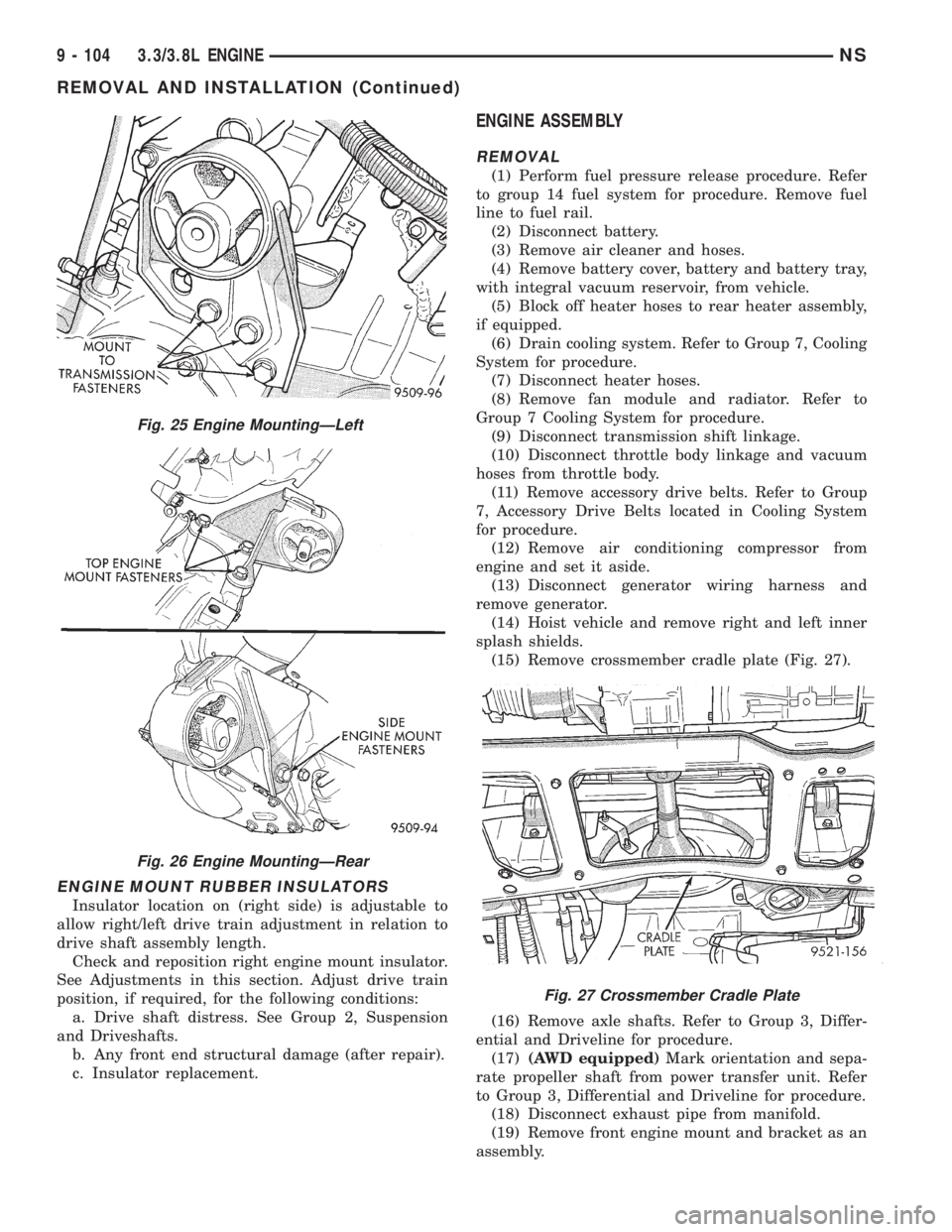
(15) Remove crossmember cradle plate (Fig. 27).
(16) Remove axle shafts. Refer to Group 3, Differ-
ential and Driveline for procedure.
(17)(AWD equipped)Mark orientation and sepa-
rate propeller shaft from power transfer unit. Refer
to Group 3, Differential and Driveline for procedure.
(18) Disconnect exhaust pipe from manifold.
(19) Remove front engine mount and bracket as an
assembly.
Fig. 25 Engine MountingÐLeft
Fig. 26 Engine MountingÐRear
Fig. 27 Crossmember Cradle Plate
9 - 104 3.3/3.8L ENGINENS
REMOVAL AND INSTALLATION (Continued)
Page 1155 of 1938
(20) Remove rear transmission mount and bracket.
(21) Remove power steering pump and bracket
assembly.
(22) Remove wiring harness and connectors from
front of engine.
(23) Remove bending braces and install tool num-
ber 6912 on engine.
(24) Remove transmission inspection cover and
mark flexplate to torque converter.
(25) Remove driveplate to torque converter bolts.
(26) Lower the vehicle.
(27) Remove ground straps to body.
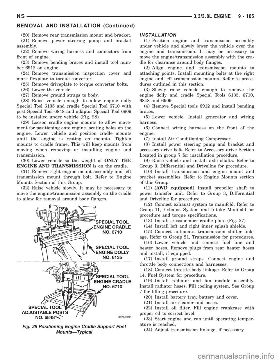
(28) Raise vehicle enough to allow engine dolly
Special Tool 6135 and cradle Special Tool 6710 with
post Special Tool 6848 and adaptor Special Tool 6909
to be installed under vehicle (Fig. 28).
(29) Loosen cradle engine mounts to allow move-
ment for positioning onto engine locating holes on the
engine. Lower vehicle and position cradle mounts
until the engine is resting on mounts. Tighten
mounts to cradle frame. This will keep mounts from
moving when removing or installing engine and
transmission.
(30) Lower vehicle so the weight ofONLY THE
ENGINE AND TRANSMISSIONis on the cradle.
(31) Remove right engine mount assembly and left
transmission mount through bolt. Refer to Engine
Mounts Section of this Group.
(32) Raise vehicle slowly. It may be necessary to
move the engine/transmission assembly on the cradle
to allow for removal around body flanges.INSTALLATION
(1) Position engine and transmission assembly
under vehicle and slowly lower the vehicle over the
engine and transmission. It may be necessary to
move the engine/transmission assembly with the cra-
dle for clearance around body flanges.
(2) Align engine and transmission mounts to
attaching points. Install mounting bolts at the right
engine and left transmission mounts. Refer to proce-
dures outlined in this section.
(3) Slowly raise vehicle enough to remove the
engine dolly and cradle Special Tools 6135, 6710,
6848 and 6909.
(4) Remove Special tools 6912 and install bending
braces.
(5) Lower vehicle. Install generator and wiring
harness.
(6) Connect wiring harness on the front of the
engine.
(7) Install Air Conditioning Compressor.
(8) Install power steering pump and bracket and
accessory drive belt. Refer to Accessory drive Section
Located in group 7 for installation procedure.
(9) Raise vehicle and install axle shafts. Refer to
Group 3, Differential and Driveline for procedure.
(10) Install transmission and engine mount and
bracket assemblies. Refer to Engine Mounts section
of this Group.
(11)(AWD equipped)Install propeller shaft to
power transfer unit. Refer to Group 3, Differential
and Driveline for procedure.
(12) Connect exhaust system to manifold. Refer to
Group 11, Exhaust System and Intake Manifold for
procedure and torque specifications.
(13) Install crossmember cradle plate (Fig. 27).
(14) Install left and right inner splash shields.
(15) Connect automatic transmission shifter link-
age. Refer to Group 21, Transmission for procedures.
(16) Lower vehicle and connect fuel line and
heater hoses. Remove plugs from rear heater hoses
and install, if equipped.
(17) Install ground straps. Connect engine and
throttle body connections and harnesses.
(18) Connect throttle body linkage. Refer to Group
14, Fuel System for procedure.
(19) Install radiator and fan module assembly.
Install radiator hoses. Fill cooling system. See Group
7 for filling procedure.
(20) Install battery tray, battery and cover.
(21) Install air cleaner and hoses.
(22) Install oil filter. Fill engine crankcase with
proper oil to correct level.
(23) Start engine and run until operating temper-
ature is reached.
(24) Adjust transmission linkage, if necessary.
Fig. 28 Positioning Engine Cradle Support Post
MountsÐTypical
NS3.3/3.8L ENGINE 9 - 105
REMOVAL AND INSTALLATION (Continued)
Page 1642 of 1938
CAUTION: A certain amount of oil will drain out of
the transaxle when the drive shaft is removed.
(2) Remove right front drive shaft. Install a plug
into the right driveshaft seal hole. Refer to Group 2,
Suspension to remove or install wheel hub nut and
right drive shaft.
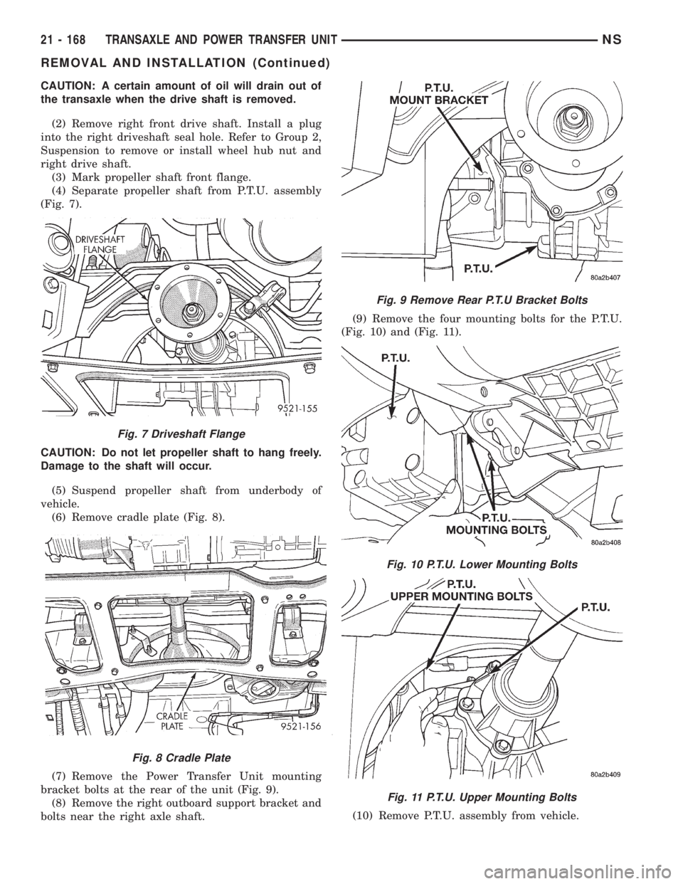
(3) Mark propeller shaft front flange.
(4) Separate propeller shaft from P.T.U. assembly
(Fig. 7).
CAUTION: Do not let propeller shaft to hang freely.
Damage to the shaft will occur.
(5) Suspend propeller shaft from underbody of
vehicle.
(6) Remove cradle plate (Fig. 8).
(7) Remove the Power Transfer Unit mounting
bracket bolts at the rear of the unit (Fig. 9).
(8) Remove the right outboard support bracket and
bolts near the right axle shaft.(9) Remove the four mounting bolts for the P.T.U.
(Fig. 10) and (Fig. 11).
(10) Remove P.T.U. assembly from vehicle.
Fig. 7 Driveshaft Flange
Fig. 8 Cradle Plate
Fig. 9 Remove Rear P.T.U Bracket Bolts
Fig. 10 P.T.U. Lower Mounting Bolts
Fig. 11 P.T.U. Upper Mounting Bolts
21 - 168 TRANSAXLE AND POWER TRANSFER UNITNS
REMOVAL AND INSTALLATION (Continued)
Page 1646 of 1938
REMOVAL
(1) Raise vehicle on hoist.
(2) Remove propeller shaft.
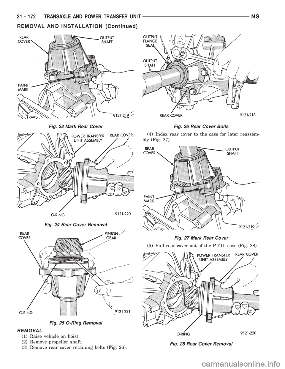
(3) Remove rear cover retaining bolts (Fig. 26).(4) Index rear cover to the case for later reassem-
bly (Fig. 27).
(5) Pull rear cover out of the P.T.U. case (Fig. 28).
Fig. 23 Mark Rear Cover
Fig. 24 Rear Cover Removal
Fig. 25 O-Ring Removal
Fig. 26 Rear Cover Bolts
Fig. 27 Mark Rear Cover
Fig. 28 Rear Cover Removal
21 - 172 TRANSAXLE AND POWER TRANSFER UNITNS
REMOVAL AND INSTALLATION (Continued)
Page 1648 of 1938
(4) Install rear cover. Use care not to cut rear
cover O-Ring when installing rear cover into P.T.U.
housing.
(5) Install rear cover retaining bolts and tighten to
28 N´m (250 in. lbs.).
(6) Install propeller shaft.
(7) Check and fill fluids as required.
INPUT SHAFT COVER SEAL
The power transfer unit input shaft cover seal is
the larger of the two seals located on the inside of
the end cover. The differential bearing cup must be
removed to service this seal.
The Power Transfer Unit must be removed from
vehicle to perform this operation.
REMOVAL
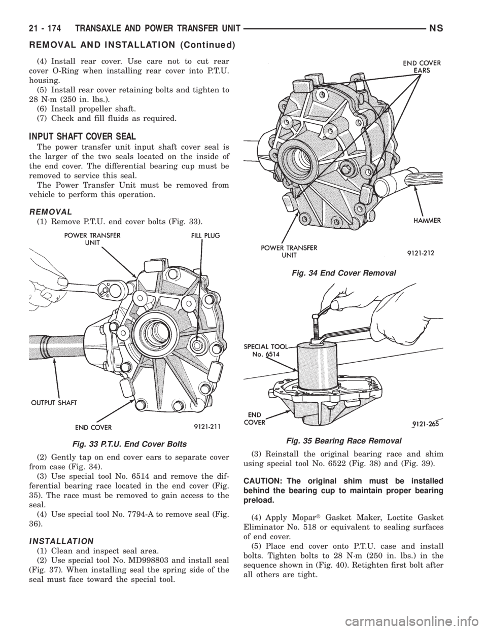
(1) Remove P.T.U. end cover bolts (Fig. 33).
(2) Gently tap on end cover ears to separate cover
from case (Fig. 34).
(3) Use special tool No. 6514 and remove the dif-
ferential bearing race located in the end cover (Fig.
35). The race must be removed to gain access to the
seal.
(4) Use special tool No. 7794-A to remove seal (Fig.
36).
INSTALLATION
(1) Clean and inspect seal area.
(2) Use special tool No. MD998803 and install seal
(Fig. 37). When installing seal the spring side of the
seal must face toward the special tool.(3) Reinstall the original bearing race and shim
using special tool No. 6522 (Fig. 38) and (Fig. 39).
CAUTION: The original shim must be installed
behind the bearing cup to maintain proper bearing
preload.
(4) Apply MopartGasket Maker, Loctite Gasket
Eliminator No. 518 or equivalent to sealing surfaces
of end cover.
(5) Place end cover onto P.T.U. case and install
bolts. Tighten bolts to 28 N´m (250 in. lbs.) in the
sequence shown in (Fig. 40). Retighten first bolt after
all others are tight.
Fig. 33 P.T.U. End Cover Bolts
Fig. 34 End Cover Removal
Fig. 35 Bearing Race Removal
21 - 174 TRANSAXLE AND POWER TRANSFER UNITNS
REMOVAL AND INSTALLATION (Continued)